
MILWAUKEE ELECTRIC TOOL CORPORATION
13135 W. Lisbon Road, Brookfi eld, WI 53005
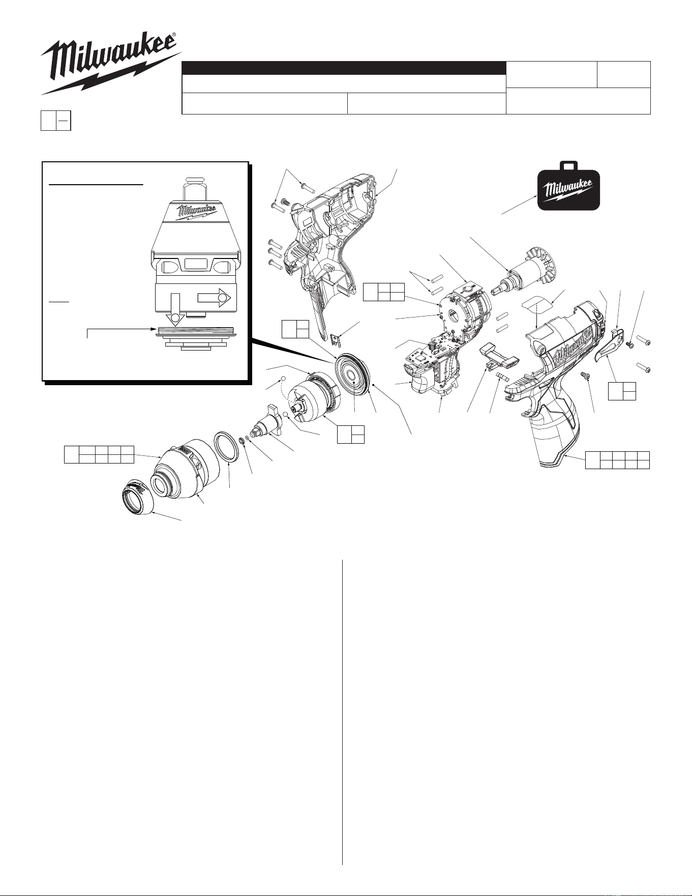
Drwg. 1
BULLETIN NO.
54-26-2473
SERVICE PARTS LIST
FIG. PART NO. DESCRIPTION OF PART NO. REQ.
1 31-12-0600 Rubber Cap (1)
2 34-40-1880 1/4" O-Ring (1)
3 44-90-1070 1/4" Friction Ring (1)
6 --------------- Anvil Bushing (Not Shown) (1)
9 45-88-2135 Plastic Washer (1)
11b 42-06-0200 1/4" Square Anvil (1)
12 02-02-1300 5mm Steel Ball (1)
19 02-02-0180 4.7mm Steel Ball (2)
22 --------------- Ball Bearing (1)
23 --------------- Gearcase End Cap (1)
24 --------------- Ring Gear (1)
25 44-66-1065 Gearcase End Cap Assembly (1)
27 --------------- Stator Assembly (1)
28 45-30-0300 Rubber Slug (4)
34 --------------- PCBA (1)
35 --------------- On-Off Switch (1)
36 --------------- Terminal Block Assembly (1)
37 45-24-0810 Fwd/Rev Shuttle (1)
38 40-50-1135 Spring (1)
42 42-70-0058 Housing Clip (1)
43 --------------- Left Handle Halve with Fuel Gauge (1)
44 42-70-0580 Belt Clip (1)
45 --------------- Belt Hook Screw (1)
46 06-82-1090 M3 x 7mm Pan Hd. Plastite Screw (2)
47 --------------- Right Handle Halve (1)
48 12-20-2435 Service Nameplate (Not Shown) (1)
49 42-55-1060 Carrying Case (1)
CATALOG NO. 2452-20
REVISED BULLETIN
SPECIFY CATALOG NO. AND SERIAL NO. WHEN ORDERING PARTS
M12 Brushless 1/4" Square Impact Driver
STARTING
SERIAL NO.
DATE
Aug. 2014
WIRING INSTRUCTION
C09D
EXAMPLE:
Component Parts (Small #)
Are Included When Ordering
The Assembly (Large #).
0
00
SEE PAGES 2 and 3
FIG. PART NO. DESCRIPTION OF PART NO. REQ.
50 06-82-7236 4-20 x 5/8" Pan Hd. Plastite T-10 Scr (7)
56 14-30-1180 Gearcase Assembly (1)
57 28-50-0930 Front Gearcase with Bushing (1)
58 42-70-0490 Belt Clip Assembly (1)
59 16-07-0420 Rotor Assembly (1)
60 31-44-2453 Handle Assembly (1)
61 14-30-1210 Impacting Assembly (1)
62 14-20-1525 Electronics Assembly (1)
63 23-66-2455 POP Switch (1)
64 10-20-2845 Spanish/French Warning Label (1)
70 23-94-2120 U-Shaped Stamping/Wire Kit (Page 2) (1)
FIG. LUBRICATION
(Type 'J' Grease, No. 49-08-4220):
11b Lightly coat front washer surface of anvil (11b) with grease.
24,61 Lightly coat the I.D. of the ring gear (24) and the center of
the planet gears of impacting assembly with grease.
57 Coat inside of bushing inside front gearcase with grease.
59 Coat pinion of rotor assembly (59) with grease.
54-26-2472
1
2
1
57
9
22
24
19(2x)
11b
12
61
24
42
28(4x)
63
59
27
34
35
49
58
44
45
62
27 34
35 36
Torque to 260 in/lbs ±24 in/lbs
(300 kgf-cm ±27 kgf-cm)
56
2 3 6 9
11b 25 57
25
22
23
36
23
3
2
See page two for
components and
installation of the High
Voltage protection system
NOTE: Components of the impacting assembly
(61) can drop out of the gearcase (57). Care
must be taken to hold those elements in
place when assembling onto the
gearcase end cap (25).
IMPORTANT NOTE: Gearcase end cap #25 is
LEFT HAND THREAD!
As an aid to assembly,
carefully lower the complete
front end of tool (gearcase /
impacting system) onto the
gearcase end cap. Gently
hand tighten front end
assembly onto gearcase
end cap. Be careful not
to cross-thread! Once
installed by hand, seat
gearcase end cap with a
good adjustable wrench
using light pressure.
Do not over tighten!
LEFT HAND THREAD
50(7x)
47
46(2x)
37 38
60
28 43 46 47
48 50 64
64 43 44 45
= Part number change
from previous service
parts list.
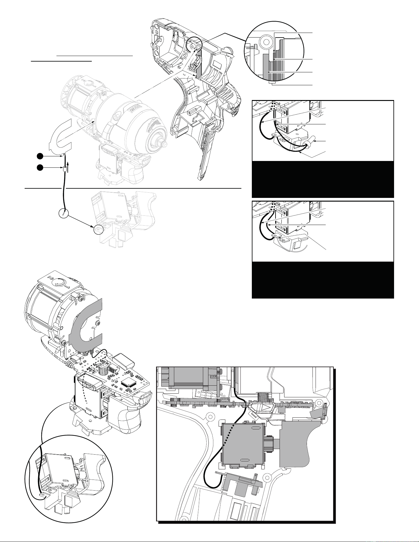
PRODUCTION WIRING- For ease in production, the
Electronics Assembly (Switch, Stator, PCBA and
BatteryTerminal Block) has a short HV wire pre-
soldered to the negative terminal. During production
a longer HV wire (with a U-Shaped Stamping) is
joined to short wire with an closed end connector.
Black wire soldered to
negative terminal & PCBA
Long HV wire to
U-Shaped Stamping
Closed End Connector
Short HV wire soldered
to negative terminal
SERVICE WIRING- When installing a service re-
placement U-Shaped Stamping/Wire Kit (23-94-2120)
it is recommended to snip old HV wire system at
battery terminal. Remove and discard that short wire,
closed end connector and longer wire with U-Shaped
Stamping. Follow instructions to install new wire kit.
Black wire soldered to
negative terminal & PCBA
23-94-2120 U-Shaped
Stamping/Wire Kit
(Kit must be assembled,
see steps 1 and 2 above)
Snip short production
HV wire at terminal here
Recess in left handle halve for
U-Shaped Stamping
U-Shaped Stamping
(Grounding Plate)
Gearcase End Cap
Gearcase End Cap groove for
U-Shaped Stamping
Route wire
around PCBA
and fwd./rev.
shuttle (See
below). Solder this
end of wire to rear left
terminal on battery
connector block.
NOTE: Switch and connector
block are shown without wires
for clarity.
To assemble U-Shaped Stamping/Wire Kit
No. 23-94-2120:
1. Trim any excess wire stranding from 115mm
wire. Place wire through hole in small tab of
stamping. Twist metal strands to temporarily
hold wire to stamping. Trim any excess wire
stranding. Be sure to position wire straight
down at the 6:00 position. Secure with minimal
solder to the strands.
2. Feed heat shrink tubing over the wire and slide up
over soldered tab. Use a heat gun to heat
the tubing to tighten/shrink around
soldered tab.
2
1
Kit consists of:
1 U-Shaped
Stamping
1 115mm Wire
1 Shrink Tube
3. Remove Electronic/Gearcase Assemblies from
housing halves.
4. Place U-Shaped Stamping onto groove of gearcase
end cap with small tab/wire positioned at the bottom.
Route the wire to the left side (behind) the PCBA.
5. Loosly install the Electronic/Gearcase Assembly (with
the U-Shaped Stamping/Wire Assembly in place) into
the Left Housing Halve. Wire is to be positioned
behind the fwd./rev. shuttle. Be sure the U-Shaped
Stamping is properly seated in the recess of the housing. (See detail above).
6. Take the loose end of the kit wire and place metal wire strands onto negative terminal of the battery terminal block
(rear left side with black wire attached to it). Secure that end with a minimal amount of solder.
7. Press all electronic components in place and route all wires in the left handle halve according to the wiring
diagram on page two. Be sure all mechanical and electrical components are firmly seated. Be sure all wires are
pressed firmly down in traps. Be sure that the fwd./rev. shuttle and spring are reinstalled and function properly.
8. Carefully install Right Housing Halve being sure that there are no interferences. Secure with existing screws.
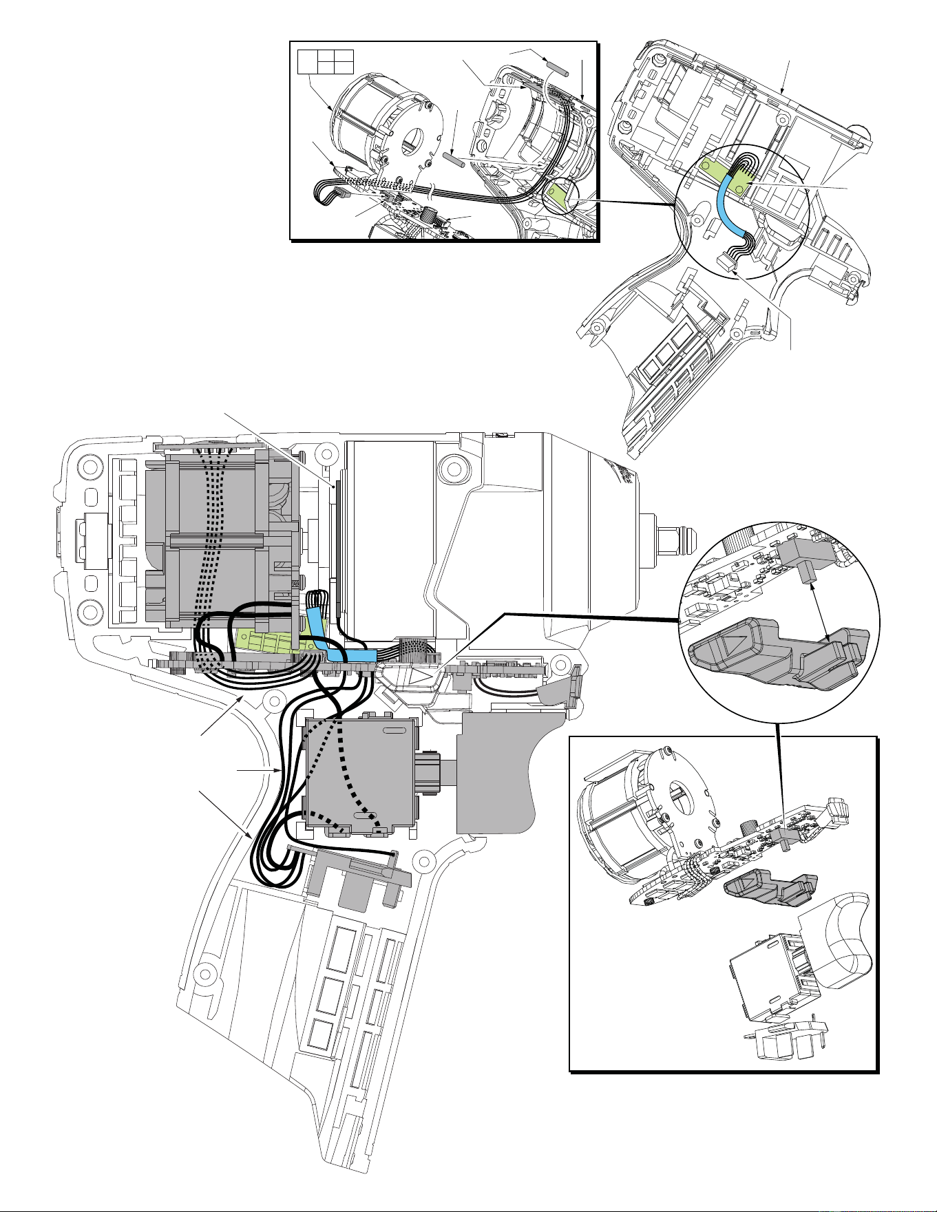
34
43
The fuel gauge assembly is a fixed component of the left
handle halve (43). Connect the five wire terminal block to
the corresponding five wire port on the PCBA.
Place POP Switch (63) into top slot of left handle halve.
Be sure that the ‘2’ is positioned to the back of tool.
Route the four wires through the channel along the
inside wall as shown. Trap the wires in place using
two Rubber Slugs (28). Carefully place all components
of the Electronics Assembly (62) into the handle halve.
Connect the four wire terminal to the port on PCBA (34).
63 28
28
62
27 34
35 36
43
4 wire
port
5 wire
port
5 wire terminal block to
5 wire port on the PCBA
Fuel
Gauge
NOTE:
It is very important to make
sure that wires are tucked down
into the left handle halve to avoid
wires being pinched when
re-assembling tool.
Be sure that all elements of
the Electronics Assembly
(On-Off Switch, PCBA,
LED, Terminal Block
Connector and Stator)
are properly seated into
the left handle halve
before re-assembly.
When installing the Fwd/Rev
Shuttle, be sure to properly
capture the slide button of
the fwd/rev micro switch
on the PCBA with the
front cavity of the shuttle.
Once in the left handle halve,
be careful that no wires
interfer with the travel of the
Fwd/Rev Shuttle.
U-Shaped Stamping (Ground Plate)
placed in center groove of gearcase
end cap
AS AN AID TO REASSEMBLY,
TAKE NOTICE OF WIRE ROUTING
AND POSITION IN WIRE GUIDES AND
TRAPS WHILE DISMANTLING TOOL.
BE CAREFUL AND AVOID PINCHING
WIRES BETWEEN HANDLE HALVES
WHEN ASSEMBLING.