
7a 7b
7c 7d
7
1 2 3
55 56 70
60
28
42
43
50
51
41
(4x)
36
37
67
13
55
15
16
17
18
20
22
23
24
27
69
9
10
56
11
12
56
57
58
59
1
(4x)
3
56
7d
8
4
6
7a
7b
7c
14
21
70
2(4x)
50 51
52
64
14
15
68
Slug
placement is
for both handle halves.
52
29
19
42
56
As an aid to reassembly,
tighten first two screws as
indicated. Secure housing
halves by the alternate
fastening of the remaining
screws
1
2
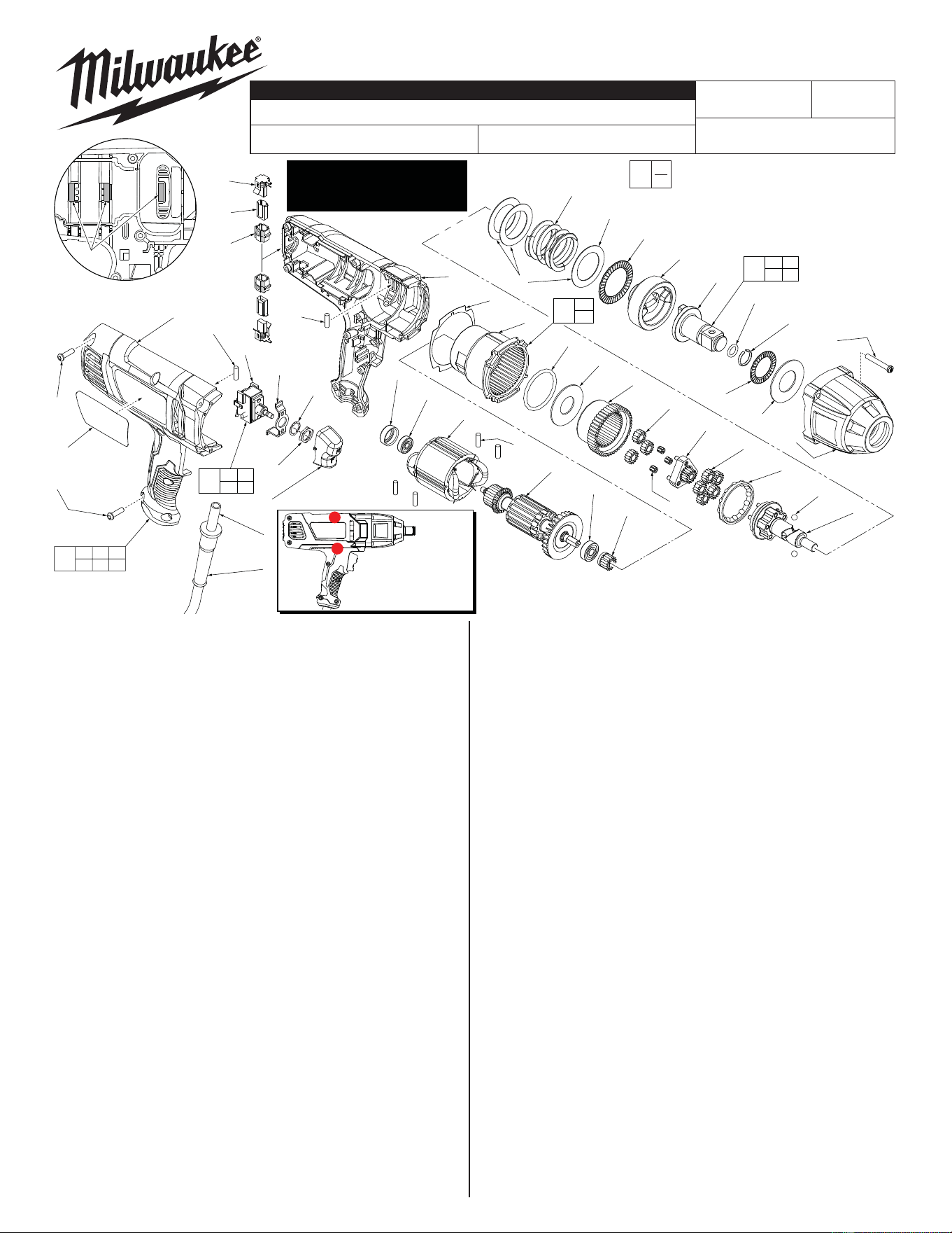
BULLETIN NO.
SERVICE PARTS LIST
54-26-1777
54-26-1778
Nov. 2013
REVISED BULLETIN
DATE
WIRING INSTRUCTION
See Page 2
239D
STARTING
SERIAL NO.
9075-20
CATALOG NO.
3/4" D.I. IMPACT WRENCH
SPECIFY CATALOG NO. AND SERIAL NO. WHEN ORDERING PARTS
MILWAUKEE ELECTRIC TOOL CORPORATION
13135 W. LISBON RD., BROOKFIELD, WI 53005
Drwg. 3
FIG. PART NO. DESCRIPTION OF PART NO.REQ.
59 22-20-0465 Brush Tube Holder (2)
60 31-44-0975 Housing Assembly (1)
64 14-73-0156 3/4" Anvil Assembly (1)
67 14-38-0130 Front Housing Assembly
Contains Bushing and two O-Rings (1)
68 28-14-0005 Gearcase Assembly (1)
69 14-73-0300 Cam Shaft Assembly (1)
70 12-20-9090 Service Nameplate (1)
0
EXAMPLE:
Component Parts (Small #) Are Included
When Ordering The Assembly (Large #).
00
Replace the Gasket (13)
whenever the tool is opened
for servicing.
FIG. NOTES:
10 Orient bearing seal (black side) toward the commutator.
41 Torque to 37-42 in./lbs (42-48 kg/cm).
1 Torque to 20-25 in./lbs (23-29 kg/cm). (Longer handle screw).
2 Torque to 17-22 in./lbs (20-25 kg/cm). (Shorter handle screw).
57 At the time of brush replacement, the tool should be relubricated
with Type "Z" Grease, No.49-08-7655.
When servicing, remove 90-95% of the existing grease prior
to installing Type “Z”. Original grease may be similar in color
but not compatible with “Z”.
FIG. LUBRICATION (Type "Z" Grease, No.49-08-7655):
18,43, Lightly coat with grease the Ring Gear (18) and the bearing races
67,69 of the Camshaft Planet Carrier (69), the back bearing surface of
the Ram (43) and the I.D. the Bushing in the Front Housing
Assembly (67).
50 Place a dab of grease inside the rear hole of the Anvil (50).
20,22 Fill with grease the center of the fi ve Planet Gears (23) on the
23,69 Camshaft Assembly (69). Fill the center of the three Planet Gears
(23) on the Sun Gear (22).
43 Place approximately 1/2 oz. grease in the front cavity of the Ram.
69 Place approximately 1/2 oz. grease on the Camshaft (69) inside
the Spring (28).
FIG. PART NO. DESCRIPTION OF PART NO.REQ.
1 06-95-6290 M5 x 18mm Pan Hd. Plast. T-20 Screw (4)
2 06-95-6215 M5 x 14mm Pan Hd. Plast. T-20 Screw (4)
3 --------------- Handle Cover (Right Side) (1)
4 22-64-0975 Power Cord (1)
6 44-76-0210 Cord Protector (1)
7 23-66-1306 Switch Assembly (1)
7a --------------- Switch (1)
7b --------------- Switch Bracket (1)
7c --------------- Supplied with Switch (1)
7d --------------- Supplied with Switch (1)
8 31-92-0060 Rocker Trigger (1)
9 42-96-0015 Bearing Cup (1)
10 02-04-0645 Ball Bearing (1)
11 18-07-2280 Service Field (1)
12 16-10-2275 Service Armature (1)
13 43-44-0992 Gasket (1)
14 02-04-0852 Ball Bearing (1)
15 28-14-0175 Gearcase (1)
16 34-40-0070 O-Ring (1)
17 45-88-3250 Washer (1)
18 32-65-0005 Gear Ring (1)
19 02-50-3250 Unit Cage Bearing (3)
20 32-62-0200 Planet Gear (3)
21 32-60-0150 Sun Gear (Pinion) (1)
22 32-60-0175 Sun Gear (Carrier) (1)
23 32-62-0215 Planet Gear (5)
24 02-40-0050 Angular Contact Bearing (1)
27 02-02-0250 1/4" Steel Ball (2)
28 40-50-0241 Spring (1)
29 02-80-0200 Thrust Needle Bearing (1)
36 02-80-3256 Thrust Bearing (1)
37 45-88-1575 Washer (1
41 05-88-5988 M5 x 35mm Pan Hd. T-20 Screw (4)
42 45-88-0535 Washer (3)
43 44-82-0210 Ram (1)
50 --------------- 3/4" Square Anvil with bearing and ball (1)
51 34-40-1210 O-Ring (1)
52 44-90-4540 Friction Ring (1)
53 23-94-9061 Wire Assembly-White (See page two) (1)
54 23-94-9062 Wire Assembly-Blue (See page two) (1)
55 --------------- Handle Support (Left Side) (1)
56 45-30-0025 Rubber Slug (6)
57 22-18-0040 Carbon Brush Assembly (2)
58 22-20-0110 Brush Tube (2)
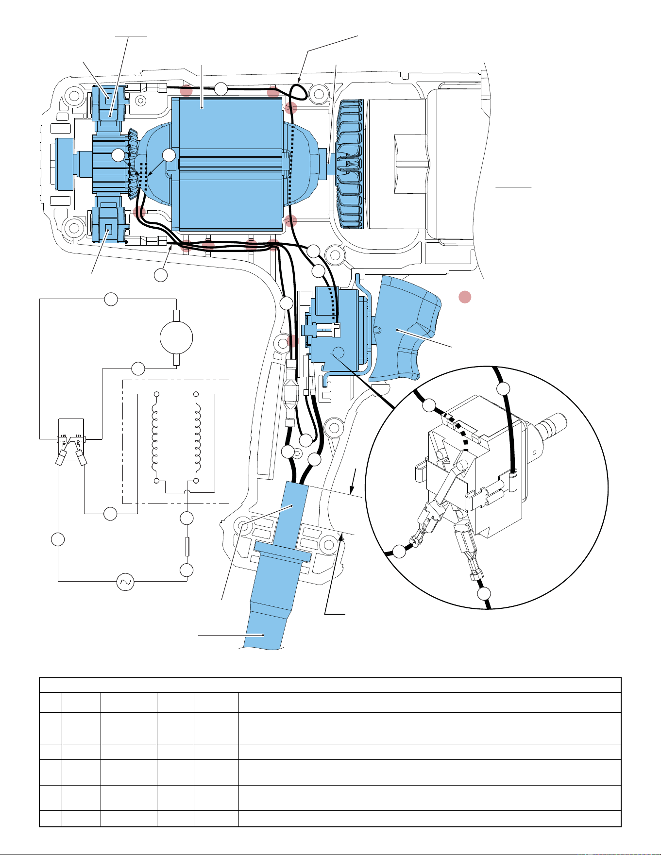
= WIRE TRAPS
or GUIDES
2
3
5
4
NOTE:
PUSH ALL WIRES FIRMLY
DOWN INTO WIRE TRAPS.
PARTICULAR CARE MUST
BE TAKEN WHEN ROUTING
LEADWIRE ASSEMBLY #5.
PUSH #5 WIRE FIRMLY INTO
WIRE TRAPS AND ONTO THE
BOTTOM OF THE LEFT
HOUSING HALVE. REMOVE
ANY SLACK AND PLACE
EXCESS WIRE WHERE
INDICATED AT THE TOP.
3
2
5
4
1
5
4
6
6
3
TOP BRUSH
ASSEMBLY FIELD ARMATURE
BOTTOM BRUSH
ASSEMBLY
SWITCH
ASSEMBLY
POWER
CORD
BARRELS OF WIRE
TERMINALS ARE
TO FACE OUT-
WARD AS
SHOWN
PLACE EXCESS FROM
LEADWIRE #5 HERE
CORD
PROTECTOR
CORD JACKET
TO EXTEND .75”-1.00” BEYOND
THE CORD CLAMPING AREA
ARM
TOP
BRUSH
BOTTOM
BRUSH
SWITCH
(Back View)
POWER
CORD
TERMINALS
2
5
1
4
6
3
White
Brown
Black
Black
Blue
White
FIELD
WIRING SCHEMATIC
DO NOT PUSH DOWN OR BEND THE BRUSH TABS.
Wire Wire Origin or
No. Color Part No. Gauge Length Terminals, Connectors and End Wire Preparation
1 White Cord Set ----- ----- Connect the female terminal with the male terminal of the brown fi eld wire #6.
2 Black Cord Set ----- ----- Attach wire terminal to switch terminal at bottom left position, barrels facing away from switch.
3 Black Field ----- ----- Attach wire terminal to switch terminal at bottom right position, barrels facing away from switch.
4 Blue 23-94-9062 ----- ----- Connect insulated wire terminal to the bottom brush terminal, barrel side up.
Connect the un-insulated wire terminal to the terminal on the right side of switch, barrel side out.
5 White 23-94-9061 ----- ----- Connect insulated wire terminal to the top brush terminal, barrel side down.
Connect the un-insulated wire terminal to the terminal on the left side of switch, barrel side out.
6 Brown Field ----- ----- Connect the male terminal with the female terminal of white cord wire #1.
WIRING SPECIFICATIONS