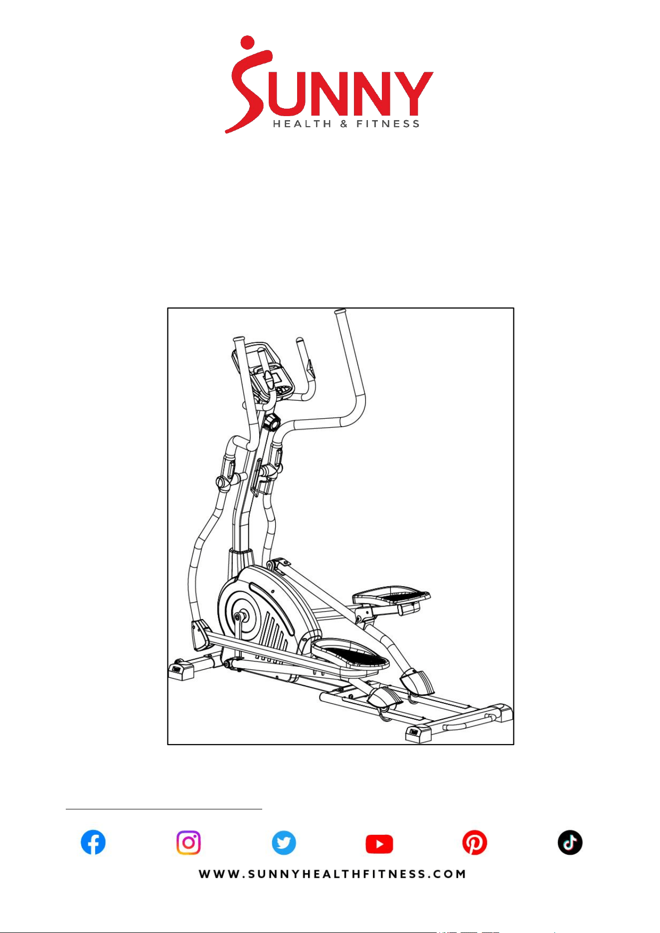
ELITE INTERACTIVE CROSS TRAINING
ELLIPTICAL
SF-E320048
USER MANUAL
IMPORTANT! Please retain owner’s manual for maintenance and adjustment instructions. Your
satisfaction is very important to us, PLEASE DO NOT RETURN UNTIL YOU HAVE CONTACTED
US: [email protected] or 1-877-90SUNNY (877-907-8669).

1
IMPORTANT SAFETY INFORMATION
We thank you for choosing our product. To ensure your safety and health, please use this
equipment correctly. It is important to read this entire manual before assembling and using the
equipment. Safe and effective use can only be achieved if the equipment is assembled, maintained,
and used properly. It is your responsibility to ensure that all users of the equipment are informed of
all warnings and precautions.
1. Before starting any exercise program, you should consult your physician to determine if you
have any medical or physical conditions that could put your health and safety at risk or prevent
you from using the equipment properly. Your physician’s advice is essential if you are taking
medication that affects your heart rate, blood pressure, or cholesterol level.
2. Be aware of your body’s signals. Incorrect or excessive exercise can damage your health. Stop
exercising if you experience any of the following symptoms: pain, tightness in your chest,
irregular heartbeat, shortness of breath, lightheadedness, dizziness, or feelings of nausea. If
you do experience any of these conditions, you should consult your physician before continuing
with your exercise program.
3. Keep children and pets away from the equipment. The equipment is designed for adult use only.
4. Use the equipment on a solid, flat level surface with a protective cover for your floor or carpet.
To ensure safety, the equipment should have at least 2 feet (60 cm) of free space all around it.
5. Ensure that all nuts and bolts are securely tightened before using the equipment. The safety of
the equipment can only be maintained if it is regularly examined for damage and/or wear and
tear.
6. Always use the equipment as indicated. If you find any defective components while assembling
or checking the equipment, or if you hear any unusual noises coming from the equipment during
exercise, discontinue use of the equipment immediately and do not use until the problem has
been rectified.
7. Wear suitable clothing while using the equipment. Avoid wearing loose clothing that may
become entangled in the equipment.
8. Do not place fingers or objects into the moving parts of the equipment.
9. The maximum weight capacity of this unit is 275 lbs (125 kgs).
10. The equipment is not suitable for therapeutic use.
11. To avoid bodily injury and/or damage to the product or property, proper lifting and moving are
required.
12. Your product is intended for use in cool, dry conditions. You should avoid storage in extreme
cold, hot, or damp areas as this may lead to corrosion and other related problems.
13. This equipment is designed for indoor and home use only; it is not intended for commercial use.
2
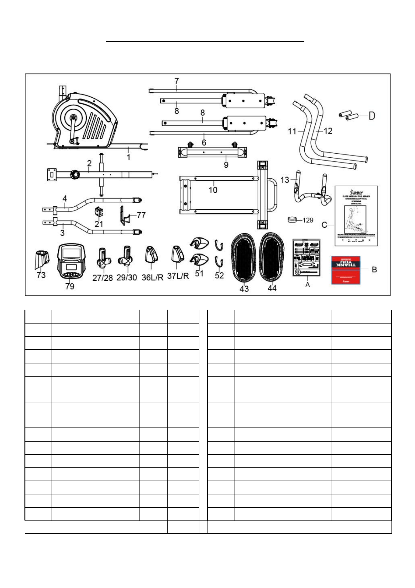
PRE-ASSEMBLY CHECK LIST
Before you start to assemble, please make sure all parts are included.
No.
Description
Spec.
Qty.
No.
Description
Spec.
Qty.
1
Main Frame
1
29/30
Right Handlebar Cover-A/B
1SETS
2
Front Post
1
36L/R
Left & Right Foot Bar Cover 1
1SETS
3
Left Swing Tube
1
37L/R
Left & Right Foot Bar Cover 2
1SETS
4
Right Swing Tube
1
43
Left Pedal
1
6/8
Left Foot Bar/ Foot Tube
Connect Patch
1SETS
44
Right Pedal
1
51
Roller Cover
2
7/8
Right Foot Bar/ Foot Tube
Connect Patch
1SETS
9
Front Stabilizer
1
52
Stopper
2
10
Rear Main Frame
1
73
Decorative Cover
1
11
Left Handlebar
1
77
Bottle Holder
1
12
Right Handlebar
1
79
Computer
1
13
Middle Handlebar
1
A
Hardware Package
1
21
Clamp Cover
1
B
Thank You Card
1
27/28
Left Handlebar Cover-A/B
1SETS
C
Manual
1
129
PTFE Lubricant
1
D
Battery
AA
2
3
HARDWARE PACKAGE
Ordering Replacement Parts (U.S. and Canadian Customers only)
Please provide the following information in order for us to accurately identify the part(s) needed:
The model number (found on cover of manual)
The product name (found on cover of manual)
The part number found on the “EXPLODED DIAGRAM” and “PARTS LIST” (found near the front
of the manual)
4
ASSEMBLY INSTRUCTIONS
We value your experience using Sunny Health and Fitness products. For assistance with parts or
(877-907-8669).
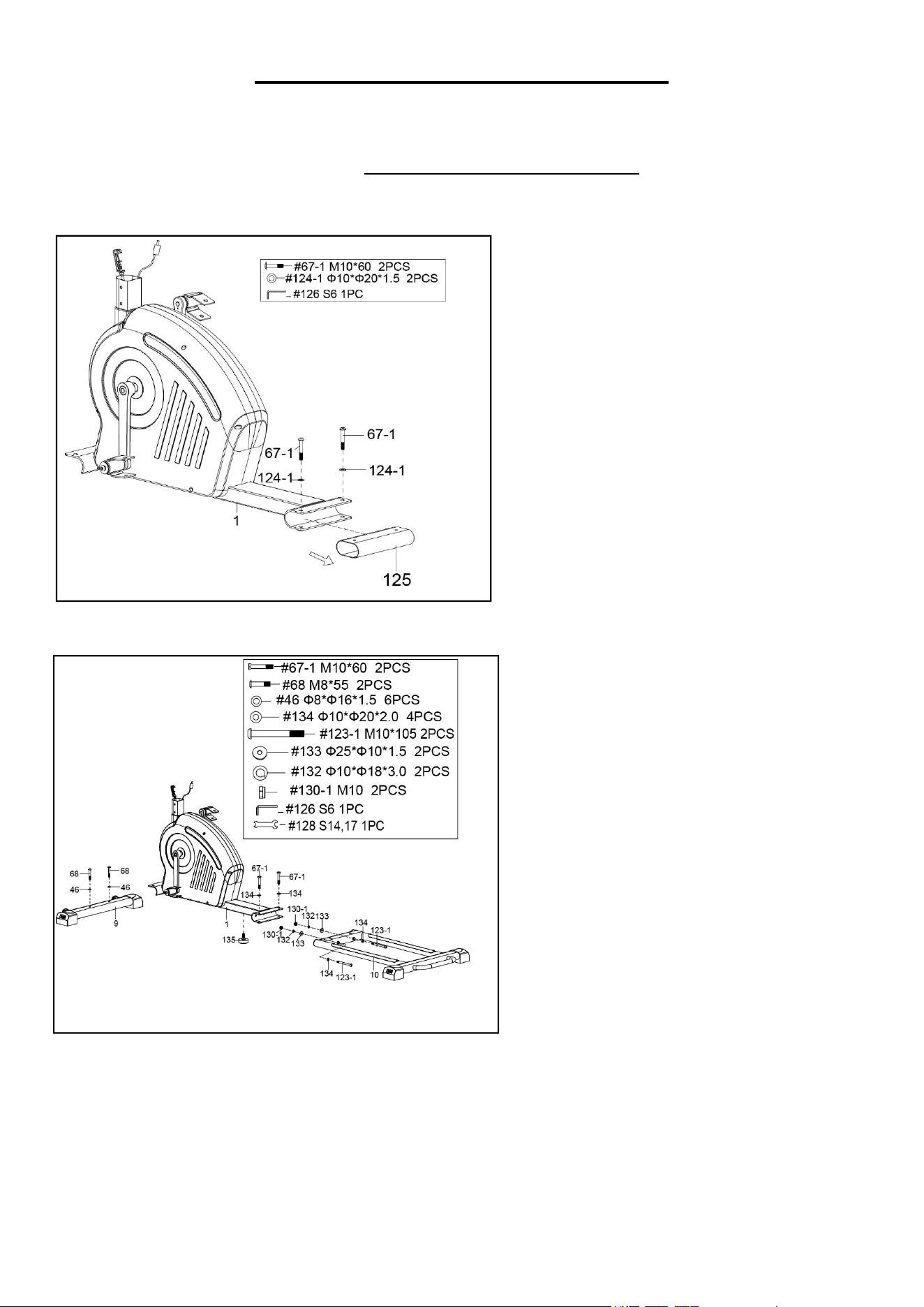
STEP 1:
Unscrew 2 Bolts (No. 67-1) from Main
Frame (No. 1) with Allen Wrench (No.
126). Remove 2 Plastic Washers (No.
124-1) and 1 Shipping Tube (No. 125)
from Main Frame (No. 1).
You may save these parts 2 Bolts (No.
67-1), Plastic Washers (No. 124-1),
Shipping Tube (No. 125) in case you
would like to repackage and transport this
equipment in the future.
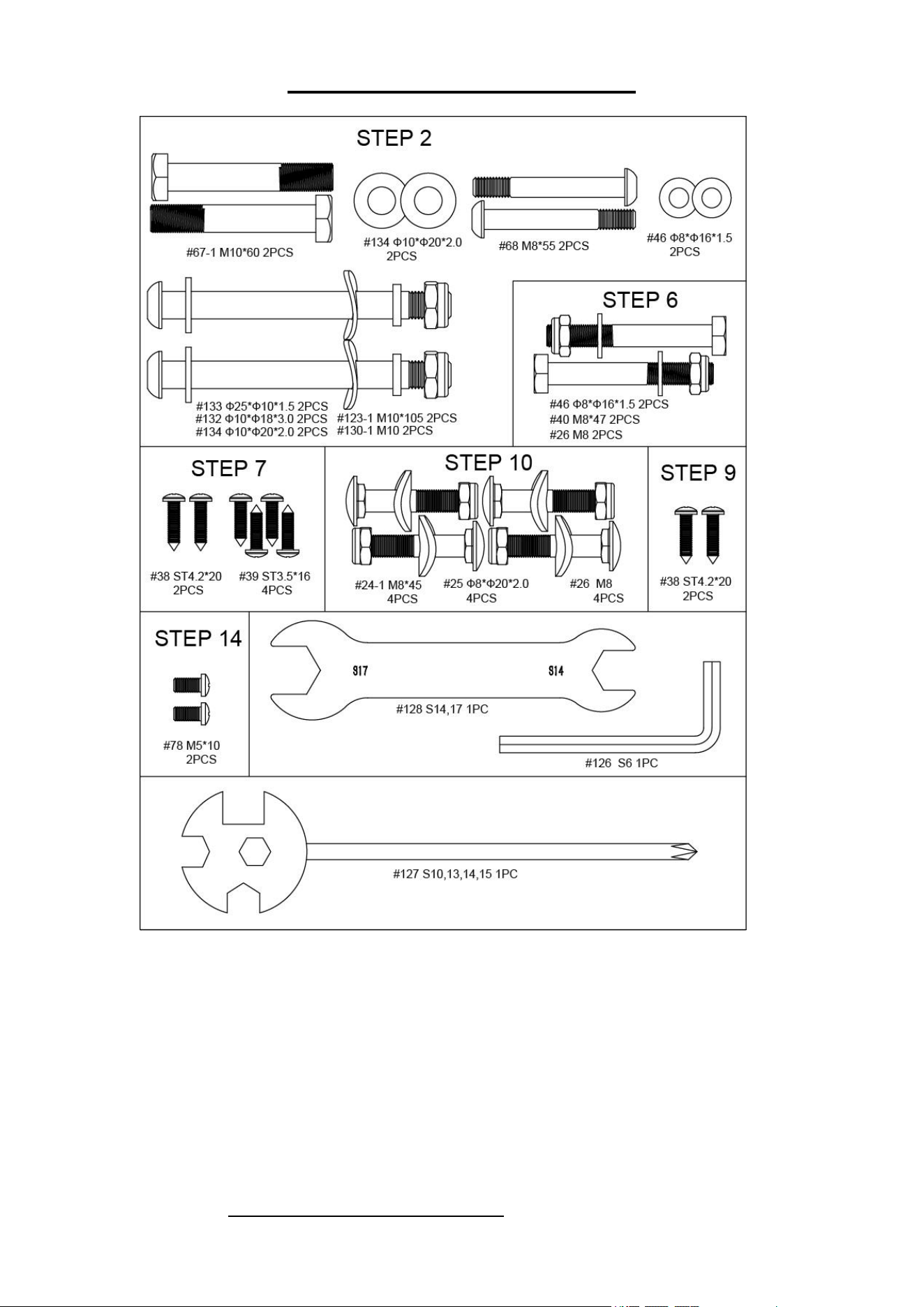
STEP 2:
Attach the Front Stabilizer (No. 9) to the
Main Frame (No. 1) with 2 Bolts (No.
68) and 2 Washers (No. 46). Tighten
and secure with Allen Wrench (No.
126).
Attach the Rear Main Frame (No. 10) to
the Main Frame (No. 1) with 2 Bolts
(No. 67-1), 2 Bolts (No. 123-1), 2 Big
Arc Washers (No. 133), 2 Spring
Washers (No. 132) 2 Nuts (No. 130-1),
and 4 Washers (No. 134). Tighten and
secure with Allen Wrench (No. 126) and
Spanner (No. 128).
Attach the Adjusting Foot Pad (No.
136) to the Main Frame (No. 1) by hand.
5
We value your experience using Sunny Health and Fitness products. For assistance with parts or
(877-907-8669).
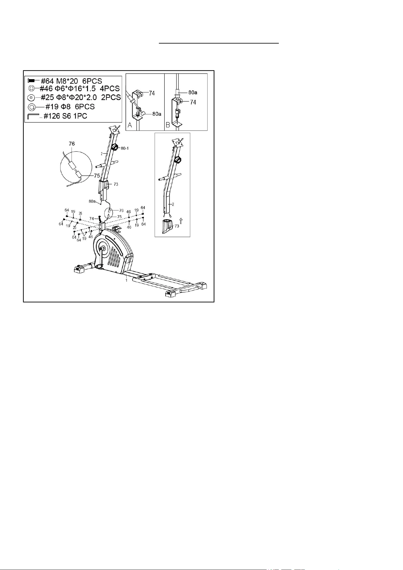
STEP 3:
Remove 6 Bolts (No. 64), 4 Washers (No.
46), 2 Big Arc Washers (No. 25) and 6
Spring Washers (No. 19) from the Main
Frame (No. 1) with Allen Wrench (No.
126).
Attach the Decorative Cover (No. 73) into
the Front Post (No. 2)
CAUTION: Please make sure the Tension
Control Knob (No. 80-1) is at the lowest
resistance level (level 1, all the way to the
left) before you connect any wires together.
Attach the Tension Control Wire (No.
80a) into the metal bracket of Tension
Wire (No. 74) as shown in drawing A.
Then, pull Tension Control Wire (No.
80a) upward and insert it into the slot of
metal bracket of Tension Wire (No. 74) as
shown in drawing B. Make sure the metal
fitting on Tension Control Wire (No. 80a)
is secured in the metal bracket.
Connect the Extension Sensor Wire (No.
76) with Sensor Wire (No. 75). Insert the
connecting wires into Front Post (No. 2).
Attach the Front Post (No. 2) to the Main
Frame (No. 1) with 6 Bolts (No. 64), 4
Washers (No. 46), 2 Big Arc Washers
(No. 25) and 6 Spring Washers (No. 19)
that were removed. Tighten and secure
with Allen Wrench (No. 126).
Lower the Decorative Cover (No. 73) to fit
in the Main Frame (No. 1).
NOTE: Be careful not to pinch any wires
when attaching Front Post (No. 2) to Main
Frame (No. 1).
6
We value your experience using Sunny Health and Fitness products. For assistance with parts or
(877-907-8669).
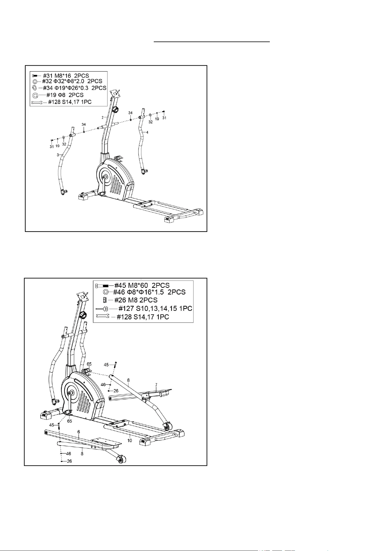
STEP 4:
Remove 2 Bolts (No. 31), 2 Spring
Washers (No. 19), 2 Big Washers (No.
32), and 2 Wave Washers (No. 34) from
the Front Post (No. 2) with Spanner (No.
128).
Attach the Left & Right Swing Tube (No. 3
& No. 4) onto the Front Post (No. 2) with 2
Bolts (No. 31), 2 Spring Washers (No.
19), 2 Big Washers (No. 32), and 2 Wave
Washers (No. 34) that were removed.
Tighten and secure with Spanner (No.
128).
STEP 5:
Remove 2 Bolts (No. 45), 2 Washers (No.
46), and 2 Nuts (No. 26) from the 2 U
Brackets (No. 65).
Attach the 2 Foot Tube Connect Patches
(No. 8) onto the 2 U Brackets (No. 65) with
2 Bolts (No. 45), 2 Washers (No. 46), and
2 Nuts (No. 26) that were removed.
Tighten and secure with Spanners (No.
127 & No. 128).
7
We value your experience using Sunny Health and Fitness products. For assistance with parts or
(877-907-8669).
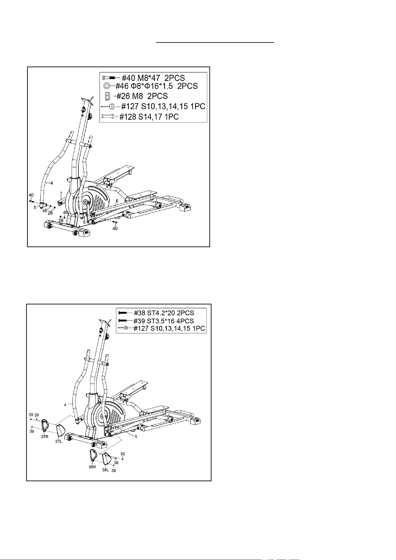
STEP 6:
Attach the Left Foot Bar (No. 6) to the Left
Swing Tube (No. 3) with 1 Bolt (No. 40), 1
Washer (No. 46) and 1 Nut (No. 26).
Tighten and secure with Spanners (No.
127 & No. 128).
Attach the Right Foot Bar (No. 7) to the
Right Swing Tube (No. 4) with 1 Bolt (No.
40), 1 Washer (No. 46) and 1 Nut (No. 26).
Tighten and secure with Spanners (No.
127 & No. 128).
STEP 7:
Attach the Foot Bar Cover 1&2 (No. 36L &
36R) to the Left Swing Tube (No. 3) with 1
Screw (No. 38) and 2 Screws (No. 39),
Tighten and secure with Spanner (No. 127).
Attach the Foot Bar Cover 3&4 (No. 37L &
37R) to the Right Swing Tube (No. 4) with
1 Screw (No. 38) and 2 Screws (No. 39),
Tighten and secure with Spanner (No. 127).
8
We value your experience using Sunny Health and Fitness products. For assistance with parts or
(877-907-8669).
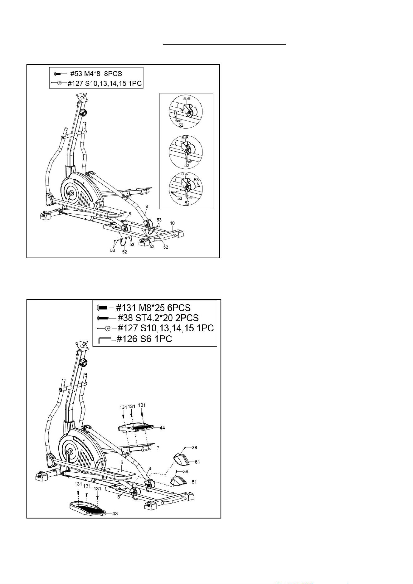
STEP 9:
Attach 2 Roller Covers (No. 51) to 2 Foot
Tube Connect Patches (No. 8) using 2
Screws (No. 38). Tighten and secure with
Spanner (No. 127).
Remove 6 Bolts (No. 131) from the Left &
Right Foot Bars (No. 6 & 7) with Allen
Wrench (No. 126).
Attach the Left & Right Pedals (No. 43 &
No. 44) onto the Left & Right Foot Bars
(No. 6 & 7) with 6 Bolts (No. 131) that
were removed. Tighten and secure with
Allen Wrench (No. 126).
STEP 8:
Remove 8 Screws (No. 53) from the ends
of 2 Foot Tube Connect Patches (No. 8)
with Spanner (No. 127).
Hoop 2 Stoppers (No. 52) under and
around the rods of the Rear Main Frame
(No. 10). Then re-attach 2 Stoppers (No.
52) to the 2 Tube Connect Patches (No.
8) with 8 Screws (No. 53) that were
removed. Tighten and secure with
Spanner (No. 127).
Note: Make sure that Foot Tube Connect
Patch (No. 8) can slide on the Rear Main
Frame (No. 10) smoothly and securely.
9
We value your experience using Sunny Health and Fitness products. For assistance with parts or
(877-907-8669).
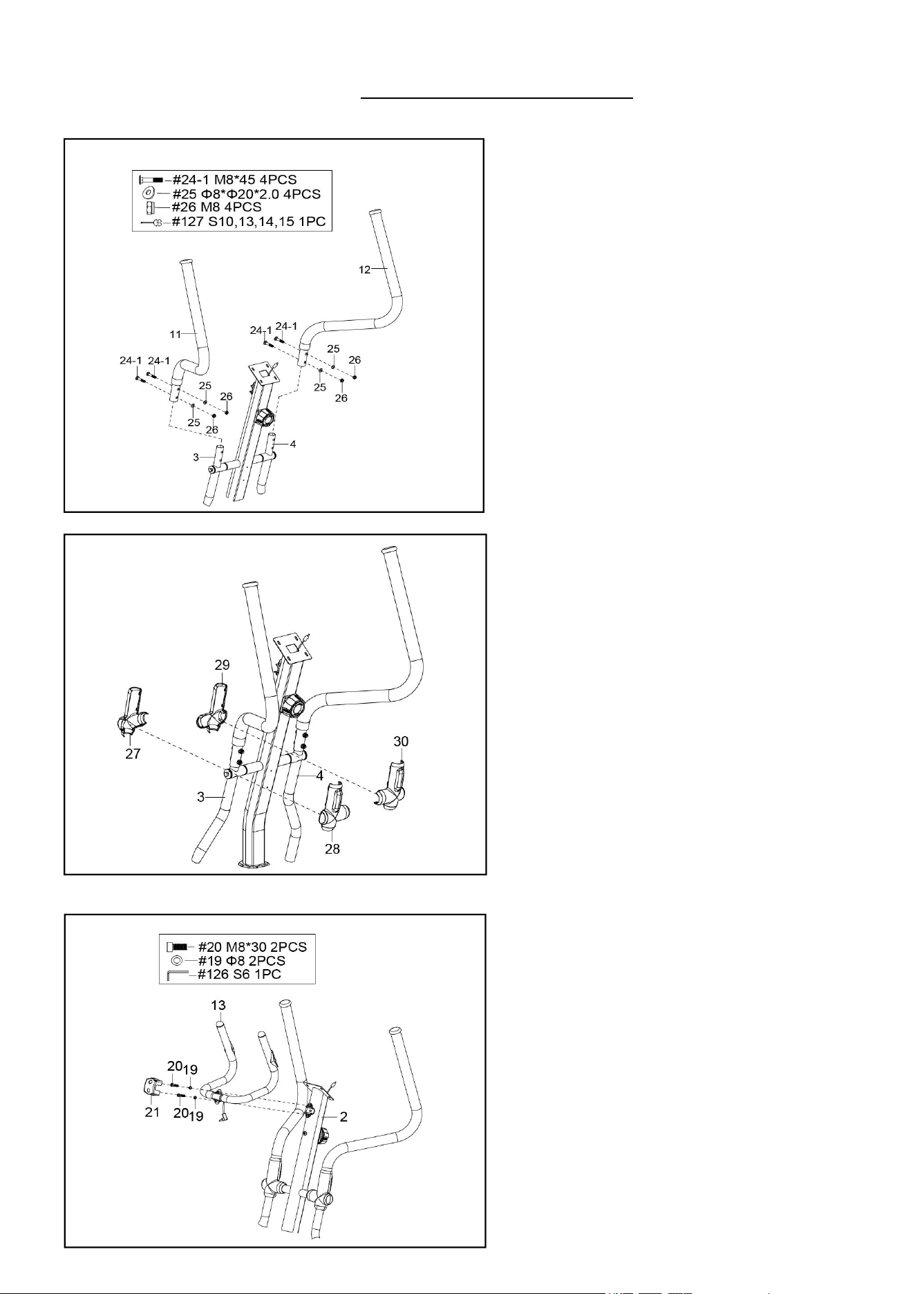
STEP 10:
Attach the Left Handlebar (No. 11) onto
the Left Swing Tube (No. 3) with 2 Bolts
(No. 24-1), 2 Big Arc Washers (No. 25),
and 2 Nuts (No. 26). Tighten and secure
with Spanner (No. 127).
Attach the Right Handlebar (No. 12) onto
the Right Swing Tube (No. 4) with 2 Bolts
(No. 24-1), 2 Big Arc Washers (No. 25),
and 2 Nuts (No. 26). Tighten and secure
with Spanner (No. 127).
STEP 11:
Attach the Left Handlebar Cover-A (No.
27) and Left Handlebar Cover-B (No. 28)
to the Left Swing Tube (No. 3) by hand.
Attach the Right Handlebar Cover-A (No.
29) and Right Handlebar Cover-B (No.
30) to the Right Swing Tube (No. 4) by
hand.
STEP 12:
Remove 2 Bolts (No. 20) and 2 Spring
Washers (No. 19) from the Front Post
(No. 2) with Allen Wrench (No. 126).
Attach the Middle Handlebar (No. 13) to
the Front Post (No. 2) with 2 Bolts (No.
20) and 2 Spring Washers (No. 19).
Tighten and secure with Allen Wrench
(No. 126).
Attach Clamp Cover (No. 21) to the
Middle Handlebar (No. 13) by hand.
10
We value your experience using Sunny Health and Fitness products. For assistance with parts or
(877-907-8669).
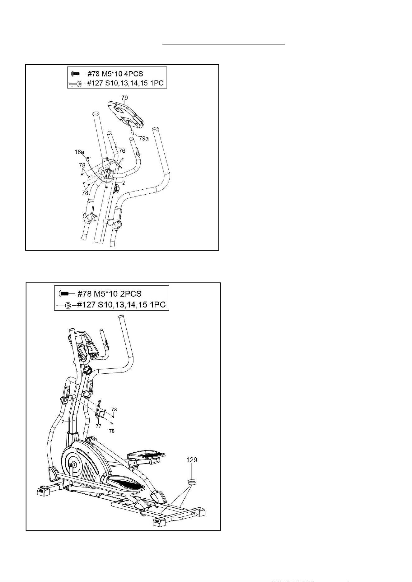
STEP 14:
Attach Bottle Holder (No. 77) to the Front
Post (No. 2) with 2 Screws (No. 78).
Tighten and secure with Spanner (No.
127).
Note: Please lubricate the Aluminum Rod
with the PTFE Lubricant (No. 129) if you
feel friction when exercising.
The assembly is complete!
STEP 13:
Remove 4 Screws (No. 78) from the back
of the Computer (No. 79) with the
Spanner (No. 127).
Connect the Extension Sensor Wire (No.
76) with Computer Wire (No. 79a). Then
insert them into the Front Post (No. 2).
Insert the Hand Pulse Sensor Wire (No.
16a) into the Pulse Input jack on the back
of Computer (No. 79).
Attach Computer (No. 79) to the top end of
the Front Post (No. 2) with 4 Screws (No.
78) that were removed. Tighten and secure
with Spanner (No. 127).
11
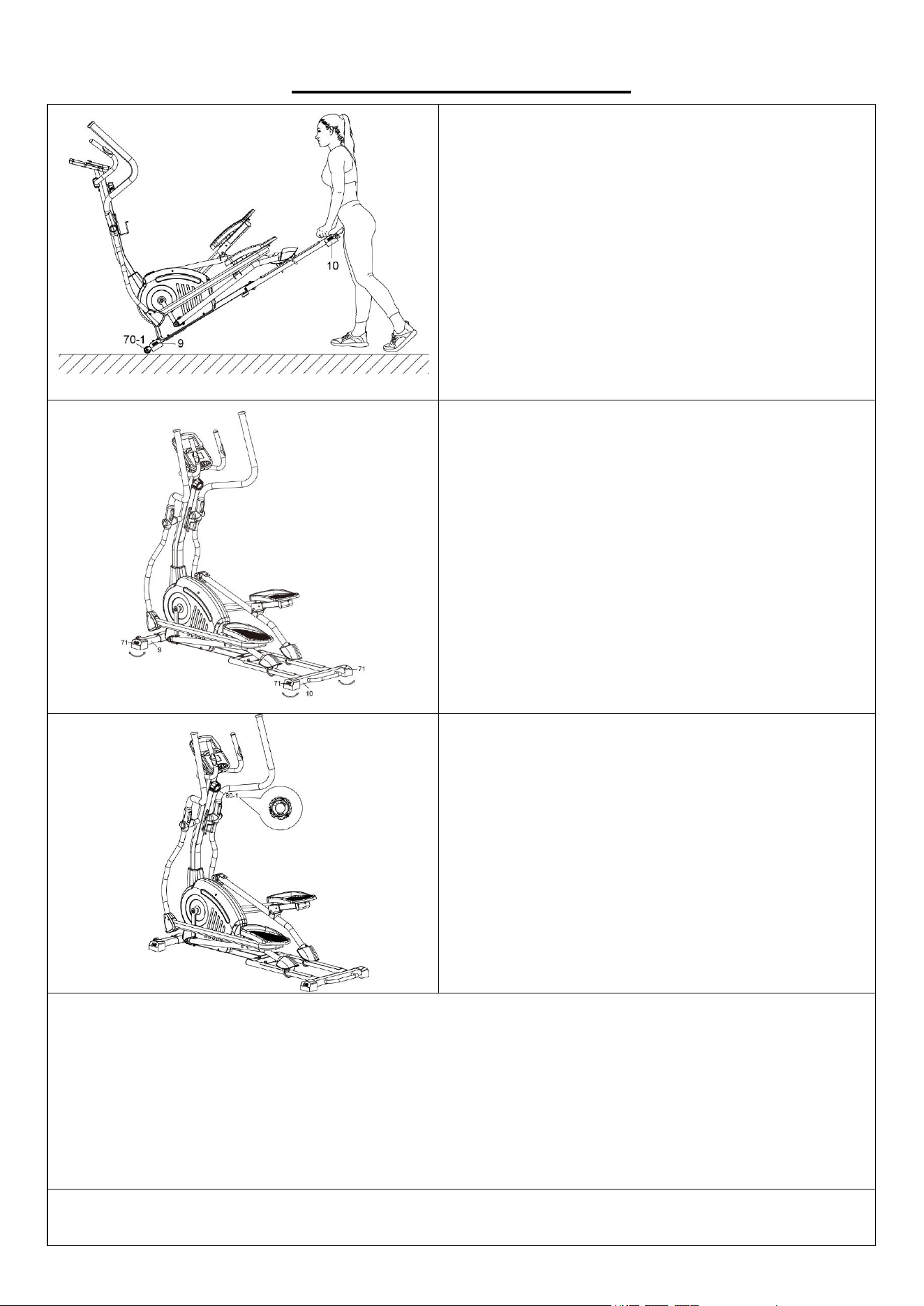
ADJUSTMENTS GUIDE
MOVING THE ELLIPTICAL BIKE
Hold the Rear Main Frame (No. 10) and pull
upward to lift the rear of the elliptical off the floor
until the Transportation Wheels (No. 70-1) on the
Front Stabilizer (No. 9) touch the ground. Now
you can move the elliptical with ease.
ADJUSTING THE BALANCE
In order to achieve a smooth and comfortable ride,
you must ensure that the elliptical is stabled and
secured. If you notice that the elliptical is
unbalanced during use, you should adjust the 6
Adjustable End Caps (No. 71) located on the
Front Stabilizer (No. 9) and Rear Main Frame
Rear Main Frame (No. 10) until the elliptical
becomes levelled with the floor surface.
ADJUSTING THE TENSION
Adjust the tension by rotating the Tension Control
Knob (No. 80-1) clockwise to increase the level of
resistance. Rotate the Tension Control Knob (No.
80-1) counter-clockwise to decrease the level of
resistance.
Tension levels are set at Level 1 being the lowest
and Level 12 being the highest.
CLEANING
The elliptical can be cleaned with a soft, clean, damp cloth. Do not use abrasives or solvents on
plastic parts. Please wipe your perspiration off the elliptical after each use. Be careful not to get
excessive moisture on the computer display panel as this might cause electrical hazard or
electronics to fail. Please keep the elliptical, especially the computer, out of direct sunlight to
prevent screen damage. Please inspect all assembly bolts and pedals on the elliptical for proper
tightness every week.
STORAGE
Store the elliptical in a clean and dry environment, away from children.
12
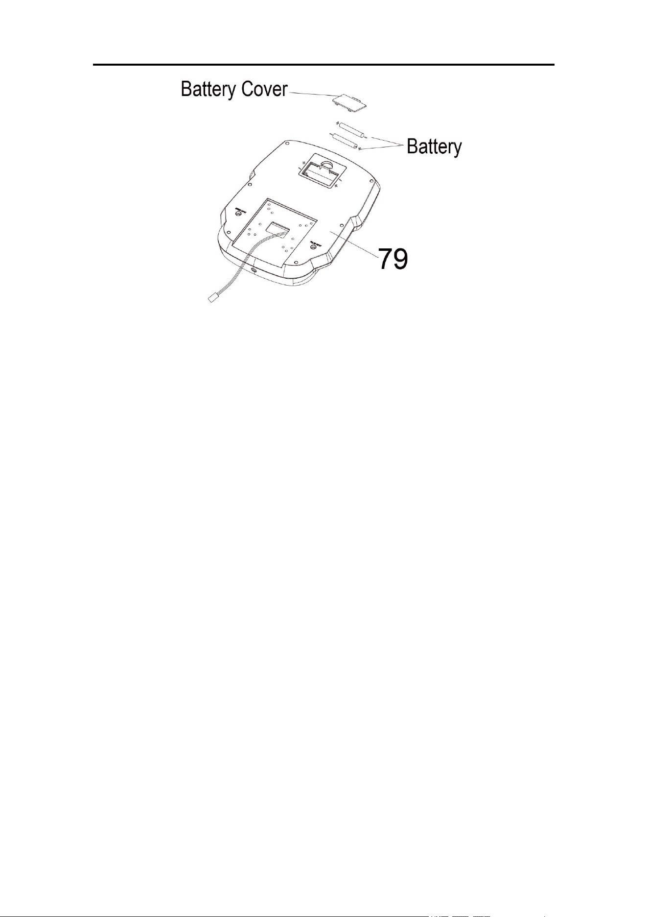
BATTERY INSTALLATION & REPLACEMENT
BATTERY INSTALLATION
1. Take out 2 AA batteries from computer box.
2. Press the buckle of battery cover on the Computer (No. 79), then remove battery cover.
3. Install 2 AA batteries into the battery case on the back of the Computer (No. 79). Pay attention
to the battery + and – poles before installing.
4. Press the buckle of battery cover, then put the battery cover back to the back of the Computer
(No. 79).
The installation is complete!
BATTERY REPLACEMENT
1. Press the buckle of battery cover on the back of the Computer (No. 79), then remove battery
cover.
2. Remove the 2 old AA batteries in the battery case and install 2 new AA batteries into the battery
case on the back of the Computer (No. 79). Pay attention to the battery + and – poles before
installing.
3. Press the buckle of battery cover, then put the battery cover back to the back of the Computer
(No. 79).
The replacement is complete!
BATTERY DISPOSAL
NOTE: Always change both batteries at the same time. Do not mix battery types and do not mix
old and new batteries. Dispose batteries according to your state and regional guidelines.

13
EXERCISE COMPUTER
FUNCTION BUTTONS
MODE
1. Press the button to select hour, minute, year, month and date for setting.
2. Press the button to select TIME, DISTANCE, CALORIES and PULSE to preset.
3. Press the button for selection function display on main LCD, or enter after setting.
4. Press the button to confirm setting value of gender, age, height and weight.
5. Press the button and hold for 2 seconds to reset all value to zero.
(When the user replace batteries, all the values will reset to ZERO automatically.)
SET
1. To set up the hour, minute, year, month and date.
2. To set up the target value of Time, Distance, Calories and Pulse. You can hold the button to
increase the value fast. (The computer has to be in stop condition.)
3. To set up the personal data of gender, age, height and weight for Body fat test.
RESET
Press the button to reset function value when setting.
(When the user replace batteries, all the values will reset to ZERO automatically.)
BODY FAT
Press this button to enter Body Fat measure function, then press MODE key to enter the setting
mode of your personal data of Gender, Age, Height and Weight. After finished setting, press it
again to measure your Body fat ration (FAT%) and BMI.
RECOVERY
To act the heart rate recovery function after pulse signal in. Press any button to return to the main
display.
FUNCTIONS
SCAN
Automatically scan through each mode in sequence every 6 seconds. The display loop is RPM
Speed – Time – Distance – Calorie - Pulse on the main screen.
TIME
Accumulates total time from 00:00 up to 99:59. The user may preset target time by pressing SET
&MODE button. Each increase is 1 minute
RPM
Displays the Rotation per Minute (RPM). The RPM and SPEED will switch to another display in
every 6 seconds after exercise starts.
SPEED
Displays current training speed. Maximum speed is 99.9 km/h or mile/h.
DISTANCE
Accumulates total distance from 0.00 up to 99.99 km or mile. The user may preset target
distance data by pressing SET & MODE button. Each increase setting is 0.5 km or mile.

14
CALORIES
Accumulates calories consumption during training from 0 to max. 999 calories. The user may also
preset the target calorie before training by press SET & MODE button. Each setting increase is10
cal.
Note : This data is a rough guide for comparison of different exercise sessions which can
not be used in medical treatment.
PULSE
The monitor will display the user's heart rate in beats per minute during training. You may set the
target heart rate by press the SET & MODE button.
CALENDAR
The monitor will display date, month, and year when the monitor is in sleep mode.
CLOCK
The monitor will display current clock time when the monitor is in sleep mode.
TEMPERATURE
Displays current room temperature from 10
℃
to 60
℃
when the monitor is in sleep mode.
OPERATION ORDER:
1. Power on – Installs 2 pieces of 1.5V UM-3 or AA batteries. The monitor start to segment test
with a long beep sound. (Whenever batteries are removed, all the functions values will be reset
to zero or default value.)
2. Set current data – Press the SET and MODE buttons to set up current clock time, year, month,
and date. After the first setting till batteries be replaced next time, those preset data will be
updated automatically.
3. Select and preset target value – Get access to the setting function of Time, Distance, Calories
and Target Pulse. When you are in each setting mode. For instance the Time setting, when
the time value is glitter, you can press the SET button to adjust the value. Press the MODE
button for confirmation and skip to next setting. The setting of Distance & Calories is the same
as Time setting.
4. After entering speed signal, each function of SPEED-RPMTIME-DISTANCE-CALORIES-
PULSE will skip to display in every 6 seconds.
5. You can also press the MODE button to select single function display on the main screen
except RPM & SPEED. The RPM & SPEED function will switch display in 6 seconds.
6. If you have preset any function target before, the function starts to count down from the target
when the training starts. Once the target is achieved, the monitor will beep and the function will
count up from zero automatically if the training is still going.
7. Pulse measurement – After you hold on two handgrip sensors in a few seconds, the monitor
will show up your current heart rate in beats per minute. To ensure the heart rate readout
precisely, please do not hold one hand only. You may preset target pulse before training starts.
Once your current heart rate is achieved to the target, the value of pulse will beep to remind
you.

15
8. Recovery – When the PULSE is working, you can press “RECOVERY” button to start the
recovery test function. The monitor will count down from 0:60 second to 0:00 and the heart beat
symbol will be glitter till counting down to “0:00”. During 60 seconds counting period, please
keep heart rate sensor is attached. Then the screen will display “F1 to F6” to show your
recovery status. F1 is the best, and the F6 is the worst. You may keep exercising to improve
your heart rate recovery status, and check it by using Recovery function.
9. Body Fat -
a) Press BODY FAT key to enter body fat measurement.
b) Press MODE and SET buttons to input your personal data. Each personal data
available setting area is described as the following:
c) AGE: 10 ~ 99 years HEIGHT: 100 ~ 250 cm (or 3’03” ~ 8’02“)
WEIGHT: 10 ~ 200 kg (or 22 ~ 440 lb)
d) After all personal data have been input, you can press BODY FAT button and hold
on grip conductors to start the body fat testing.
e) It takes few seconds to test the body fat. If you did not hold on the conductor during
the testing procedure, the LCD will show the error sign Err after 10 seconds period.
f) After the testing is finished, you will see fat advice in percentage and BMI figure
(body mass Index) display on the main LCD in sequence by scan mode.
g) BODY FAT % : Calculate from your personal data to show the value from 5%~50%.
h) BMI : Calculate from your personal data to show the value from 1.0~99.99.
i) Press any key to return to the main display.
Note
1. Stop training for 4 minutes, the screen will show up room temperature, clock, and calendar
display automatically.
2. If the computer displays abnormally, please re-install the battery and try again.
3. Battery Spec: 1.5V UM-3 or AA (2PCS).
TECHNICAL DATA
Connectivity: Bluetooth LE
Frequency Range: 2400~2483.5Mhz
Transmitting Power: 0dBm

16
APP CONNECTION:
Connect Smart Equipment to SunnyFit App:
1. Scan to download SunnyFit from the app store:
2. Ensure that the Bluetooth function is turned on from your mobile device.
3. If this is your first time using the SunnyFit app, follow the in-app instructions to register for
your free SunnyFit account and log in.
4. Begin any workout activity that matches your smart equipment, then follow the onscreen
prompts to search for and connect to your smart equipment.
5. When connected, your stats and records will be displayed at the end of your course/session,
and recorded in your account profile!
Troubleshooting:
If you are having trouble connecting your smart equipment, visit www.sunnyfit.com/guide or
scan the QR code below:
17
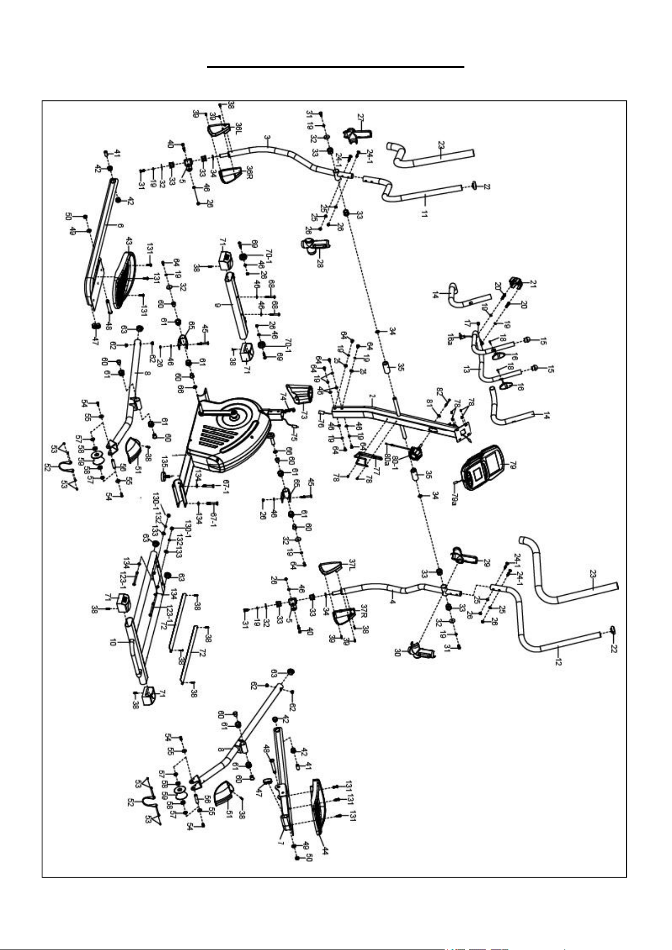
EXPLODED DIAGRAM 1
18
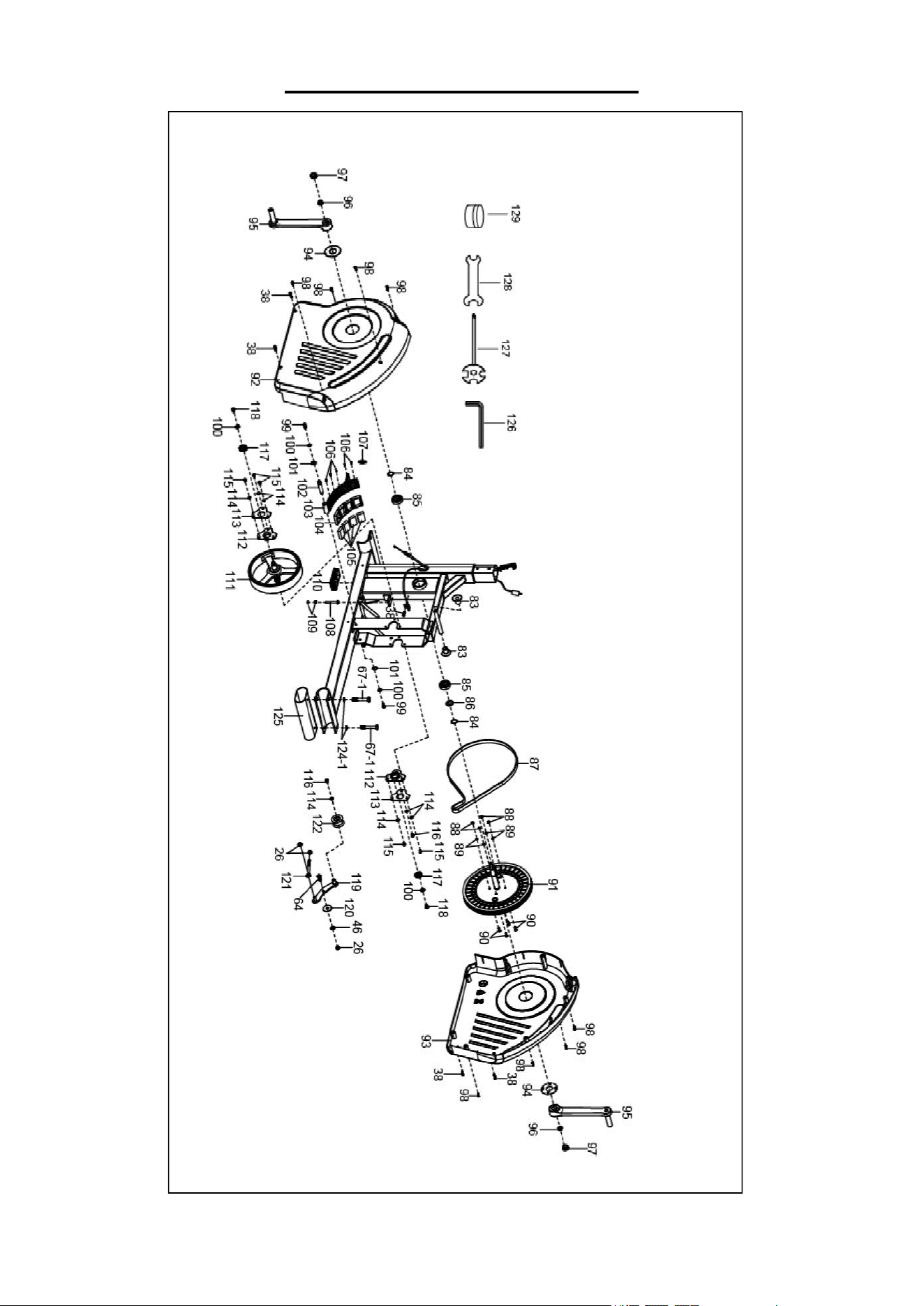
EXPLODED DIAGRAM 2
19
PARTS LIST
No.
Description
Spec.
Qty
No.
Description
Spec.
Qty
1
Main Frame
1
33
Shaft Sleeve
Φ32*3.5*24*
Φ19
8
2
Front Post
1
34
Wave Washer
Ф19*Ф26*0.3
4
3
Left Swing Tube
1
35
Bushing
Φ31.8*Φ19.2
*75
2
4
Right Swing Tube
1
36L
Left Foot Bar Cover 1
1
5
Rotating Sleeve Tube
2
36R
Right Foot Bar Cover 1
1
6
Left Foot Bar
1
37L
Left Foot Bar Cover 2
1
7
Right Foot Bar
1
37R
Right Foot Bar Cover 2
1
8
Foot Tube Connect Patch
2
38
Screw
ST4.2*20
17
9
Front Stabilizer
1
39
Screw
ST3.5*16
4
10
Rear Main Frame
1
40
Bolt
M8*47
2
11
Left Handlebar
1
41
Connecting Shaft
Ф16*32
2
12
Right Handlebar
1
42
Shaft Sleeve
4
13
Middle Handlebar
1
43
Left Pedal
1
14
Foam Grip
Ф24*Ф30*500
2
44
Right Pedal
1
15
End Cap for Handlebar
2
45
Bolt
M8*60
2
16
Hand Pulse Sensor
L=850mm
2
46
Washer
Ф8*Ф16*1.5
13
16a
Hand Pulse Sensor Wire
1
47
Cap
2
17
Plug
Ф12.1
1
48
Bolt
Φ16*88
2
18
Screw
ST4.2*20
2
49
Washer
φ24*φ12.5*2
2
19
Spring Washer
Ф8
14
50
Nut
M12
2
20
Bolt
M8*30
2
51
Roller Cover
2
21
Clamp Cover
1
52
Stopper
2
22
Cap
Ф32
2
53
Screw
M4*8
8
23
Foam Grip
Ф31*Ф41*920
2
54
Bolt
M8*20
4
24-1
Bolt
M8*45
4
55
Washer
Ф8*Ф20*2.0
4
25
Big Arc Washer
Ф8*Ф20*2.0
6
56
Roller Connecting Shaft
Ф15*61.5
2
26
Nut
M8
13
57
Roller Spacing
Ф22*2
4
27
Left Handlebar Cover-A
1
58
Bearing
6202
4
28
Left Handlebar Cover-B
1
59
Pulley
Ф70*Ф29*50
2
29
Right Handlebar Cover-A
1
60
Shaft Sleeve
Ф23.5*20
8
30
Right Handlebar Cover-B
1
61
Plastic Bushing
Ф32*21
8
31
Bolt
M8*16
4
62
Connecting Rod Small
Bushing
Ф18*Ф8*10
4
32
Big Washer
Ф32*Ф8*2.0
6
63
Cap
Ф38
4

20
No.
Description
Spec.
Qty
No.
Description
Spec.
Qty
64
Bolt
M8*20
9
100
Washer
Ф6*Ф16*1.2
4
65
U Bracket
2
101
Shaft Snap Ring
Ф12*1.0
2
66
Wave Spring Washer
Ф16*Ф21*0.3
2
102
Magnetic Plate Axle
1
67-1
Bolt
M10*60
4
103
Magnetic Bracket
1
68
Bolt
M8*55
2
104
Magnet Seat
1
69
Bolt
M8*40
2
105
Magnet
40*25*10
4
70-1
Transportation Wheel
φ50*φ22.5*8.2
2
106
Screw
ST2.9*9
5
71
Adjustable End Cap
4
107
Spring
Ф15*50*Ф1.5
1
72
Aluminum Bar
5100x321x23mm
2
108
Bolt
M6*45
1
73
Decorative Cover
1
109
Nut
M6
2
74
Tension Wire
L=1000mm
1
110
End Cap
1
75
Sensor Wire
L=750mm
1
111
Flywheel
Ф240
1
76
Extension Sensor Wire
L=1100mm
1
112
Bearing Seat
2
77
Bottle Holder
1
113
Bearing End Cover
2
78
Screw
M5*10
6
114
Washer
Ф6*Ф12*1.0
7
79
Computer
1
115
Bolt
M6*12
5
79a
Computer Wire
1
116
Bolt
M6*10
2
80-1
Tension Control Knob
L=700MM
1
117
Bearing
6001
2
80a
Tension Control Wire
1
118
Bolt
M6*12
2
81
Big Arc Washer
Ф5*Ф18*1.0
1
119
Idler Wheel Shaft
1
82
Bolt
M5*55
1
120
PC Pad
1
83
Cover Limit Column
2
121
Bolt
M8*85
1
84
C-clip
Φ20*1
2
122
Idler Wheel
1
85
Bearing
6004ZZ
2
123-1
Bolt
M10*105
2
86
Wave Washer
Φ20*Φ24*0.3
1
124-1
Plastic Washer
Ф10*Ф20*1.5
2
87
Belt
390J
1
125
Shipping Tube
1
88
Nut
M6 S10
4
126
Allen Wrench
S6
1
89
Spring Washer
Ф6
4
127
Spanner
S10,13,14,15
1
90
Bolt
M6*15
4
128
Spanner
S14,17
1
91
Belt Pulley
Φ260
1
129
PTFE Lubricant
1
92
Left Belt Cover
1
130-1
Nut
M10
2
93
Right Belt Cover
1
131
Bolt
M8*25
6
94
Crank Cover
2
132
Spring Washer
Ф10*Ф18*3.0
2
95
Crank
2
133
Big Arc Washer
Ф25*Ф10*1.5
2
96
Nut
M12*1.25
2
134
Washer
Ф10*Ф20*2.0
4
97
Crank Cap
2
135
Adjusting Foot Pad
M10*30
1
98
Screw
ST4.2*25
8
99
Bolt
M6*15 L15 S10
2
Version 1.2