360mm
280mm
240mm

2
» Product information for this CPU cooler
» Produktinformationen zu diesem CPU-Kühler
» Informations produit pour ce système de refroidissement
» Información del producto para este refrigerador de CPU
» Informacje produktowe dla tego coolera CPU
» Engelstalige productinformatie voor deze processorkoeler
» Produktinformation för den här processorkylaren, på engelska
» Подробнаяинформацияоданномкулередляпроцессора
» 此CPU散熱器的產品資訊
» 此CPU散热器的产品信息
» 製品情報CPUクーラー
NL
SE
www.bequiet.com/BW013
www.bequiet.com/BW014
www.bequiet.com/BW015
240mm
280mm
360mm
3
Einleitung: Vielen Dank, dass Sie sich für ein be quiet!
Produkt entschieden haben. Diese Anleitung wird Ihnen beim
Installationsprozess behilflich sein. Sollten bei der Installation
Schwierigkeiten auftreten, kontaktieren Sie bitte unseren
Kundenservice unter [email protected]. be quiet! kann
keinerlei Haftung für durch Kompatibilitätsprobleme bedingte
Schäden übernehmen.
Garantie:
• 3 Jahre Herstellergarantie für Endkonsumenten (nur Erst-
erwerb vom autorisierten be quiet! Händler), ab Datum
des Kaufbelegs
• Eine Garantieabwicklung ist nur in Verbindung mit einer
beigefügten Kopie des Kaufbeleges eines autorisierten
be quiet! Händlers möglich
• Manipulationen und bauliche Veränderungen jeglicher
Art, sowie Beschädigungen durch äußere mechanische
Einwirkungen führen zum totalen Garantieverlust
• Es gelten unsere allgemeinen Garantiebestimmungen, die
Sie unter www.bequiet.com im Internet abrufen können
Listan GmbH
.
Wilhelm-Bergner-Straße 11c
.
21509 Glinde
Germany
Für weitere Unterstützung erreichen Sie uns via E-Mail:
Für die Montage des Kühlers empfehlen wir die
Installation außerhalb des Gehäuses.
!
Introduction: Thank you for deciding to purchase a be quiet!
product. The following instructions will guide you through the
installation process. If you do encounter installation problems,
please don't hesitate to contact our customer services by
mailing [email protected]. Please note that be quiet! cannot
accept liability for damage caused by compatibility problems.
Warranty:
• 3-year manufacturer guarantee for consumers (original
purchase from authorized be quiet! dealers only)
• Guarantee work can only be processed with a copy
included of the purchase receipt from an authorized be
quiet! dealer
• Manipulation and structural changes of any kind, including
any damage caused by external mechanical force, will lead
to a complete voiding of the guarantee
• Our General Warranty Conditions apply, which can be
viewed on bequiet.com
Listan GmbH
.
Wilhelm-Bergner-Straße 11c
.
21509 Glinde
Germany
For further information contact us via e-mail:
We recommend preparatory mounting of the cooler
outside the PC case for subsequent installation.
!
V1/25 V1/25
FR
Cet appareil
se recycle
À DÉPOSER
EN MAGASIN
À DÉPOSER
EN DÉCHÈTERIE
OU
Points de collectes ur www.quefairedemesdechets.fr
4
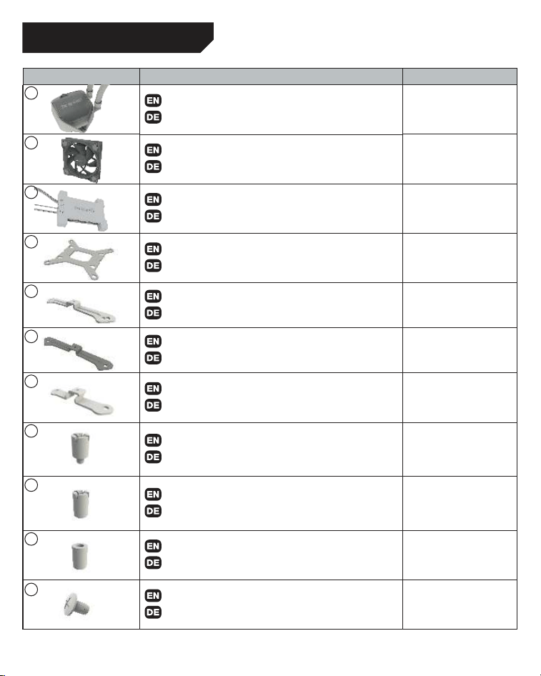
Part name / Bezeichnung Quantity / Anzahl
be quiet! Pure Loop 2 FX CPU cooler
be quiet! Pure Loop 2 FX CPU Kühler
1
Light Wings fan
Light Wings Lüfter
240 / 280: 2
360: 3
ARGB-PWM-Hub
ARGB-PWM-Hub
1
Intel backplate
Intel Backplate
1
Intel mounting brackets
Intel Montagebrücken
2
Intel mounting brackets LGA 1700
Intel Montagebrücken LGA 1700
2
Short AMD mounting brackets
Kurze AMD Montagebrücken
2
Intel spacer nut A
Intel Gewindebolzen A
4
Intel spacer nut B
Intel Gewindebolzen B
4
AMD Spacer nuts
AMD Abstandbolzen
4
Mounting bracket fastening screws
Befestigungsschrauben für die Montagebrücke
4
SCOPE OF DELIVERY / LIEFERUMFANG
1
2
3
4
5
6
7
8
9
10
11
5
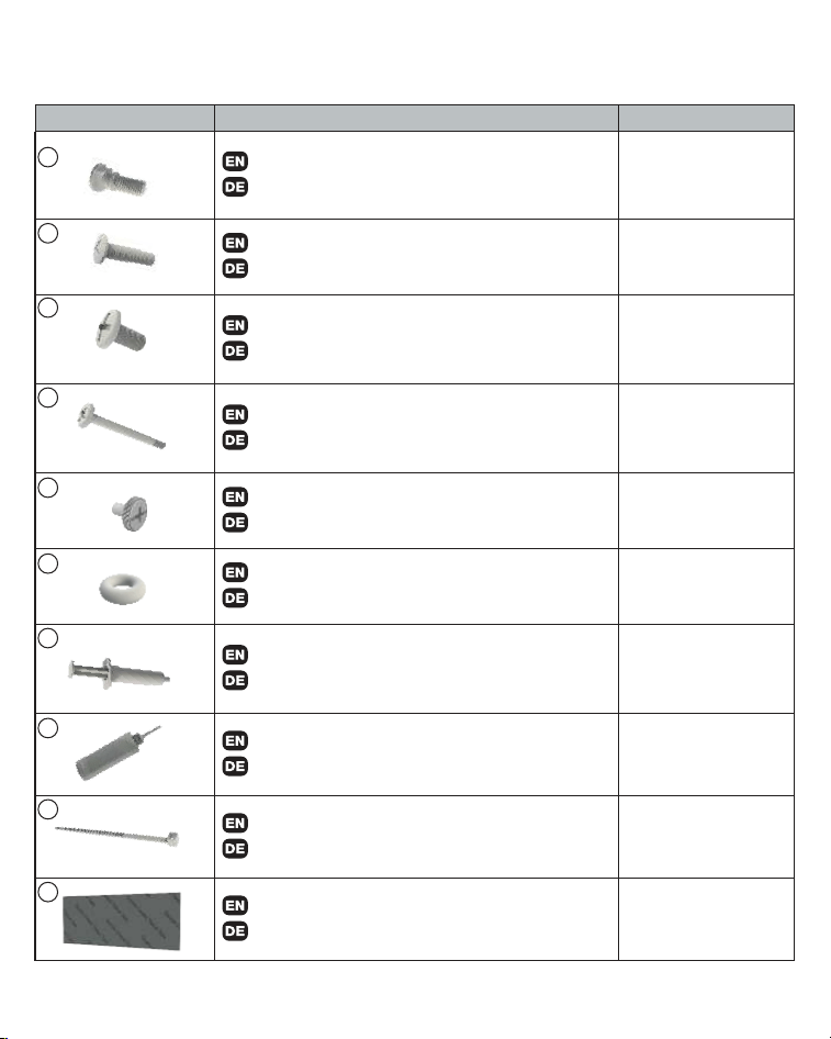
Part name / Bezeichnung Quantity / Anzahl
Intel backplate screws
Intel Backplate-Schrauben
4
AMD backplate screws
AMD Backplate-Schrauben
4
Radiator mounting screws
Radiator Befestigungsschrauben
240 / 280: 8
360: 12
Fan mounting screws
Lüfter Befestigungsschrauben
240 / 280: 8
360: 12
Hub mounting screws
Hub-Befestigungsschrauben
4
O-Rings
O-Ringe
4
Thermal paste
Wärmeleitpaste
1
Bottle of coolant
Flasche mit Kühlflüssigkeit
1
Small Cable Tie
Kleiner Kabelbinder
3
Double sided tissue tape
Doppelseitiges Klebeband
1
12
13
14
15
16
17
18
19
20
21
6
Assembly of the cooler mounting frame
Prior to mounting the cooler, please detach both
plastic holders of the AMD retention module. The
factory-mounted backplate on the rear side of the
motherboard is required for further installation of
the cooler.
Aufbau des Kühlerbefestigungsrahmens
Bitte entfernen Sie zur Kühlermontage die
beiden Kunststoffhalterungen des AMD-
Retentionmoduls. Die werkseitig auf der
Mainboard-Rückseite befestigte Backplate wird
für die weitere Installation des Kühlers benötigt.
The following parts are needed for this:
Pure Loop 2 FX CPU cooler (1), Light Wings fans (2), ARGB-PWM-Hub (3), short AMD mounting brackets
(7), AMD spacer nuts (10), AMD backplate screws (13), radiator mounting screws (14), fan mounting
screws (15), Hub mounting screws (16), thermal paste (18), double sided tissue tape (21)
Es werden folgende Bauteile benötigt:
Pure Loop 2 FX CPU-Kühler (1), Light Wings Lüfter (2), ARGB-PWM-Hub (3), kurze AMD
Montagebrücken (7), AMD Abstandsbolzen (10), AMD Backplate-Schrauben (13), Radiator
Befestigungsschrauben (14), Lüfter Befestigungsschrauben (15), Hub-Befestigungsschrauben (16),
Wärmeleitpaste (20), Doppelseitiges Klebeband (21)
AMD: AM5 / AM4
7
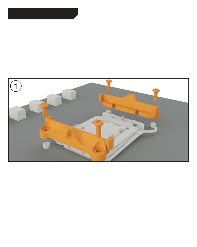
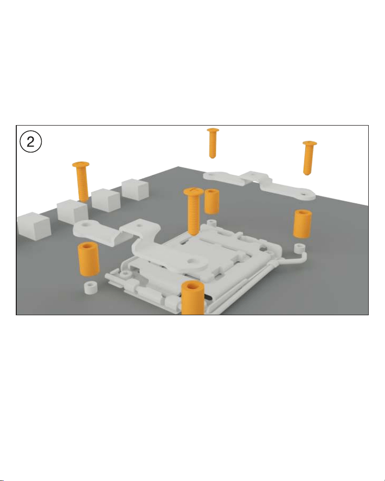
Place the four AMD spacer nuts over the bolt
threads of the backplate on the front side and
fix both the AMD mounting brackets using the
AMD backplate screws.
Platzieren Sie über die Vorderseite die vier
AMD Abstandsbolzen über den Gewinden der
Backplate und fixieren die beiden kurzen AMD
Montagebrücken mit Hilfe der AMD Backplate-
Schrauben.
8
AMD: AM5 / AM4
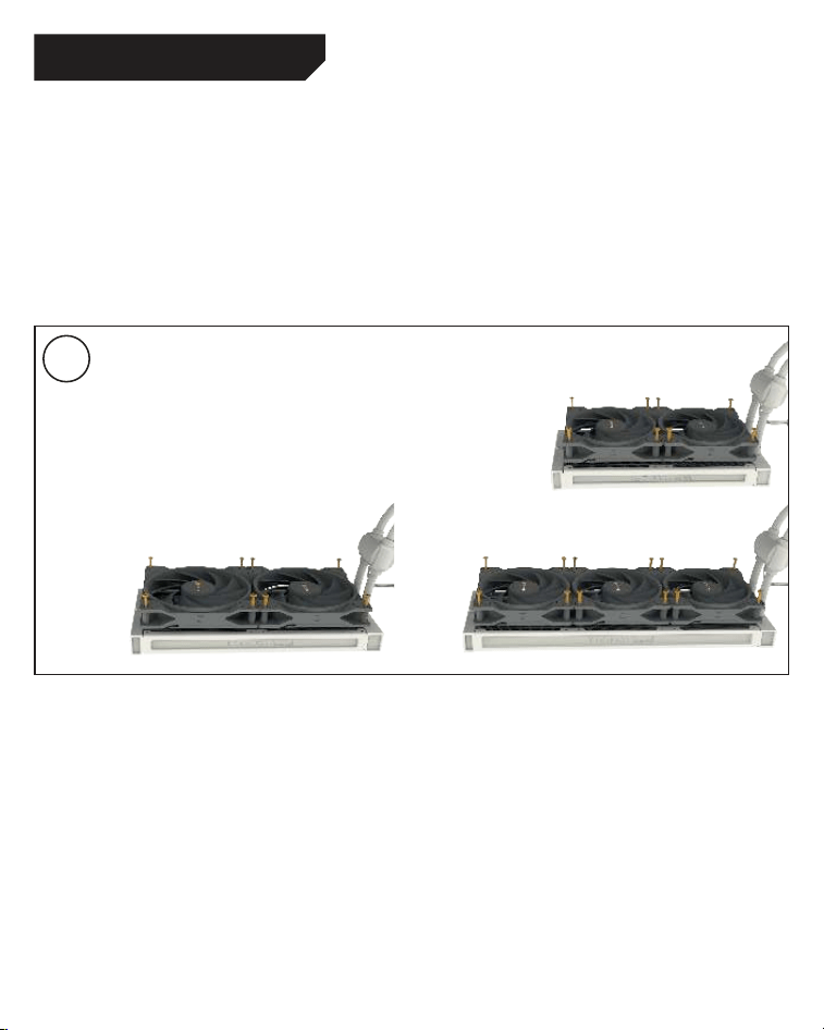
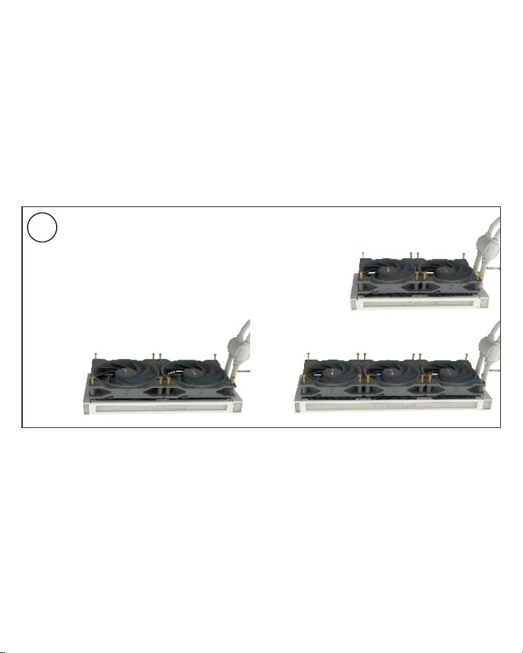
Mounting the fans on the radiator
Affix the fans to the radiator with the fan mounting
screws. We recommend installation in a push
configuration. With the fans facing towards the
model name on the radiator, mount them on the
hose side.
Befestigung der Lüfter am Radiator
Befestigen Sie die Lüfter mit den Lüfter
Befestigungsschrauben am Radiator. Wir
empfehlen die Installation in einer Push Kon-
figuration. Die Lüfter, mit der Modellbezeichnung
auf den Radiator gerichtet, montieren Sie auf
der Schlauchseite.
3
9
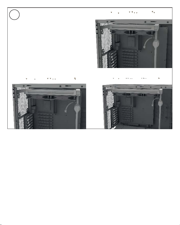
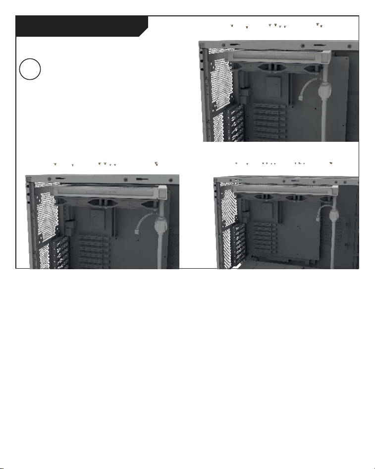
Affixing the radiator to the case
Fix the radiator of Pure Loop 2 FX with the
radiator mounting screws to the case. You can
use a normal crosshead screwdriver for this.
Befestigung des Radiators am Gehäuse
Befestigen Sie den Radiator der Pure Loop 2
FX mit den Radiator Befestigungsschrauben
am Gehäuse. Hierzu können Sie einen üblichen
Kreuz-Schraubendreher verwenden.
4
10
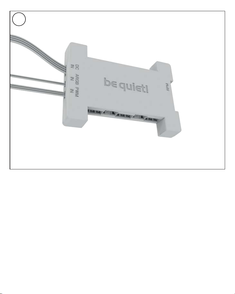
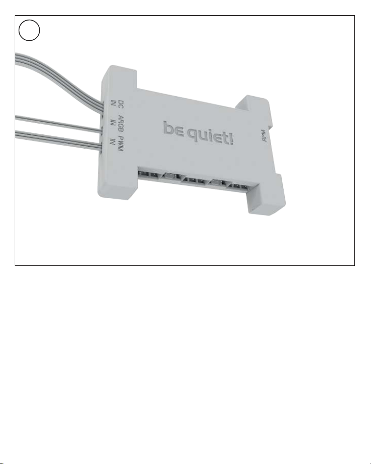
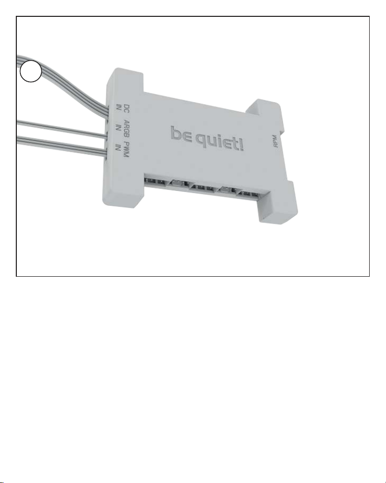
Affixing the ARGB-PWM-Hub to the case
Mount the ARGB-PWM-Hub with the Hub
mounting screws or the double sided tissue
tape on a suitable position in your PC case. We
recommend either the rear of the mainboard
tray or a 2.5” HDD slot. Next, connect the 5V
ARGB pin and the PWM pin with the mainboard.
Then connect the SATA connector with the PSU.
Now connect the ARGB connector and the
PWM connector of the fans with the ARGB-
PWM-Hub. The connector marked RPM carries
the rpm signal of the connected device to the
Mainboard fan header.
Please find further information on the
illumination on page 26.
Befestigung des ARGB-PWM-Hub am Gehäuse
Befestigen Sie den ARGB-PWM-Hub mit den Hub-
Befestigungsschrauben oder dem doppelseitigen
Klebeband an einer geeigneten Stelle im Gehäuse.
Wir empfehlen die Rückseite des Mainboard-
Schlittens oder ein 2,5”-Laufwerksschacht.
Verbinden Sie anschließend den 5V ARGB-Stecker
und den PWM-Stecker mit dem Mainboard. Den
SATA-Anschluss verbinden Sie mit dem Netzteil.
Schließen Sie nun den ARGB-Anschluss und
PWM-Anschluss der Lüfter an den ARGB-PWM-
Hub. Der Anschluss mit der Bezeichnung RPM
gibt das Tacho-Signal des angeschlossenen
Gerätes an das Mainboard weiter.
Weitere Informationen zur Beleuchtung
finden Sie auf S. 26.
4
11
AMD: AM5 / AM4
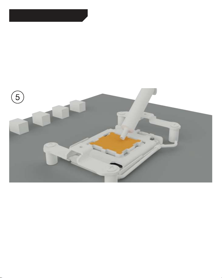
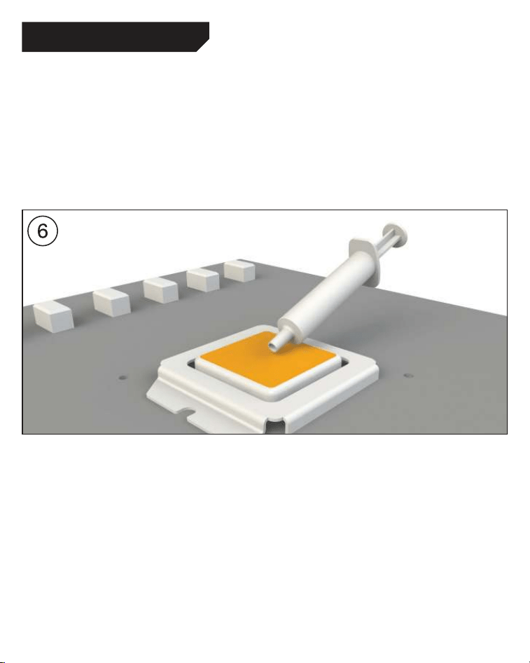
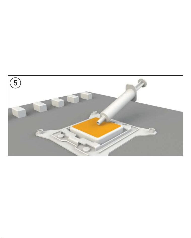
Mounting of the CPU block
First peel off the protective film from the underside
of the cooler. Apply thermal paste on the CPU
surface. The tube contains enough for about 1 or
2 applications.
Caution: The thermal paste supplied should not
be swallowed. If any is swallowed, drink lots of
water and urgently seek the advice of a doctor.
Store it beyond the reach of children. Avoid
contact with skin and eyes.
Montage des CPU-Blocks
Entfernen Sie zunächst die Schutzfolie von
der Unterseite des Kühlers. Tragen Sie die
Wärmeleitpaste auf die CPU-Oberfläche auf.
Der Inhalt reicht für ca.1-2 Anwendungen.
Vorsicht: Die mitgelieferte Wärmeleitpaste
ist nicht zum Verzehr geeignet. Bei Verzehr
ausreichend Wasser trinken und umgehend
einen Arzt aufsuchen. Außerhalb der Reichweite
von Kindern aufbewahren. Vermeiden Sie Haut-
und Augenkontakt.
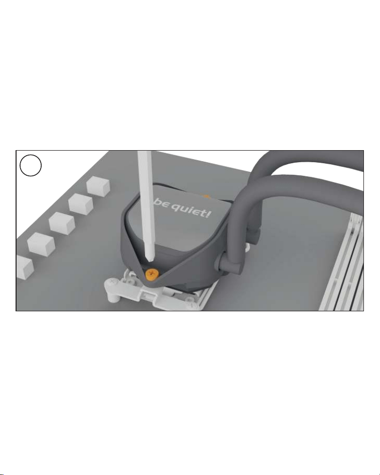
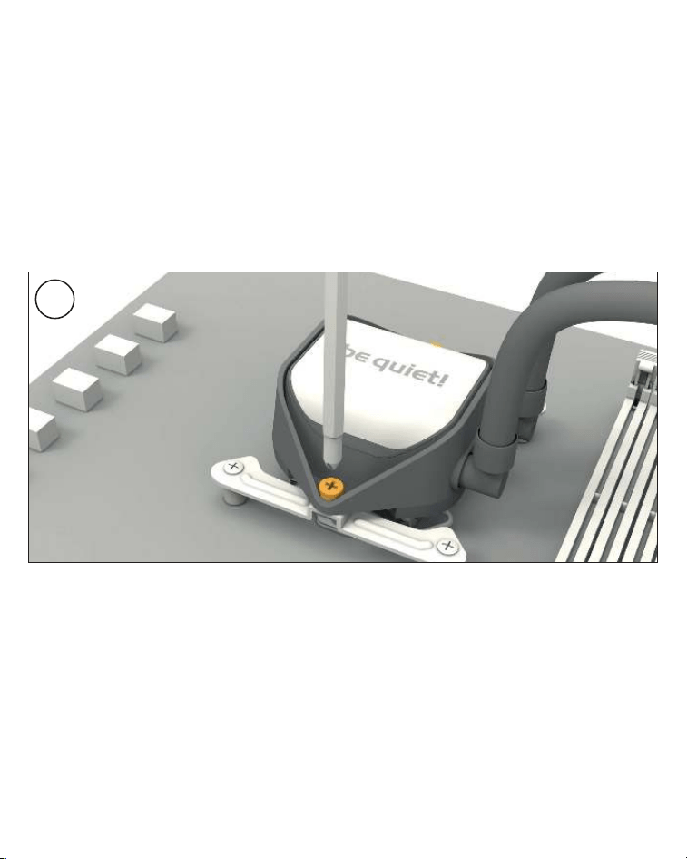
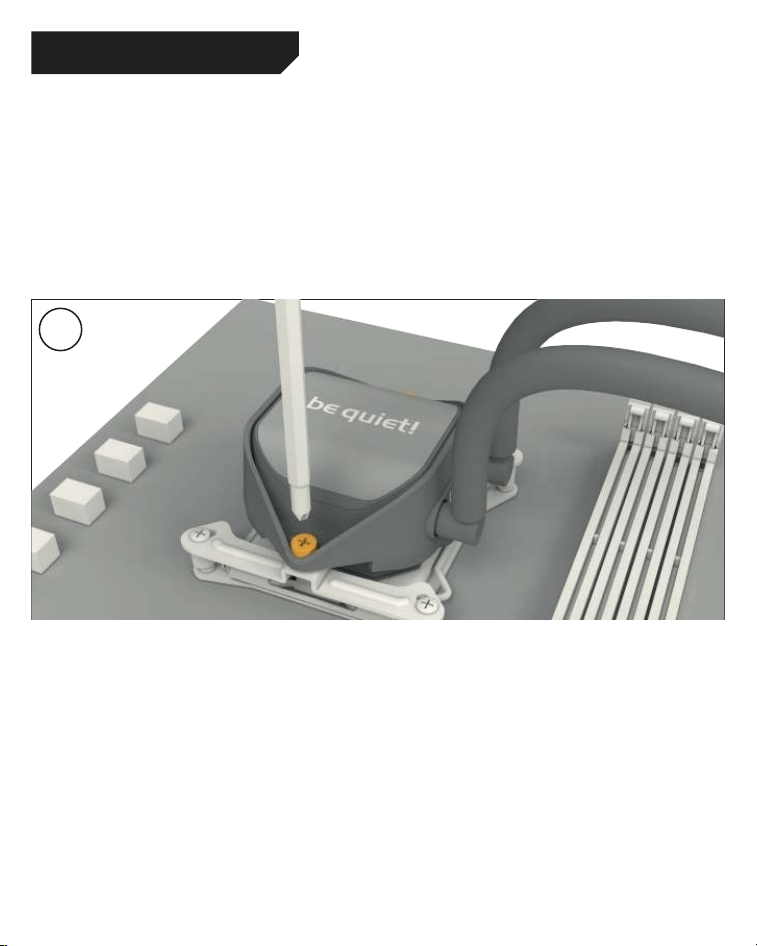
12
Place the CPU block centrally over the short
AMD mounting brackets, such that these allow
the CPU block to be screwed down. For this you
can use a normal crosshead screwdriver. Next
connect the pump and the ARGB illumination to
the ARGB-PWM-Hub.
Please continue on page 26.
Legen Sie den CPU-Block mittig auf die
kurzen AMD Montagebrücken, sodass sich
der CPU-Block mit selbigen verschrauben
lässt. Hierzu können Sie einen üblichen Kreuz-
Schraubendreher verwenden. Anschließend
schließen Sie die Pumpe sowie die ARGB
Beleuchtung an den ARGB-PWM-Hub an.
Bitte lesen Sie auf S. 26 weiter.
6
13
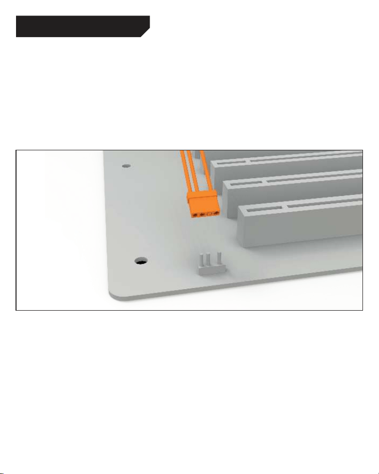
Affixing the backplate
Place the Intel backplate screws in the notches
found on the rear of the Intel backplate. Observe
the drilled holes for the actual CPU socket. Use
the O-rings to fasten the backplate screws on
the Intel backplate. Once the Intel backplate is
assembled for the actual Intel socket, position it
beneath the motherboard. Make sure that the Intel
backplate screws exactly match the positions of
the motherboard holes.
Befestigung der Backplate
Platzieren Sie die Intel Backplate Schrauben
in die auf der Rückseite der Intel Backplate
befindlichen Aussparungen. Beachten Sie
hierzu die Bohrlöcher für den jeweiligen
Sockel. Verwenden Sie zur Befestigung der
Backplate-Schrauben auf der Intel-Backplate
die O-Ringe. Sobald die Intel-Backplate für
den jeweiligen Intel-Sockel zusammengebaut
ist, positionieren Sie es unter dem Mainboard.
Achten Sie dabei darauf, dass die Intel Backplate-
Schrauben genau in den Mainboardlöchern
positioniert sind.
The following parts are needed for this:
Pure Loop 2 FX CPU cooler (1), Light Wings fans (2), ARGB-PWM-Hub (3), Intel Backplate (4), Intel
mounting brackets (5), Intel mounting brackets LGA 1700 (6), Intel spacer nut B (9), mounting bracket
fastening screws (11), Intel backplate screws (12), radiator mounting screws (14), fan mounting screws
(15), Hub mounting screws (16), O-rings (17), thermal paste (18), double sided tissue tape (21)
Es werden folgende Bauteile benötigt:
Pure Loop 2 FX CPU-Kühler (1), Light Wings Lüfter (2), ARGB-PWM-Hub (3), Intel Backplate (4), Intel
Montagebrücken (5), Intel Montage-brücken LGA 1700 (6), Intel Gewindebolzen B (9),
Befestigungsschrauben für die Montagebrücke (11), Intel Backplate-Schrauben (12), Radiator
Befestigungsschrauben (14), Lüfter Befestigungsschrauben (15), Hub-Befestigungsschrauben (16),
O-Ringe (17), Wärmeleitpaste (18), Doppelseitiges Klebeband (21)
Intel LGA 1700 / 1200 / 1150 / 1151 / 1155
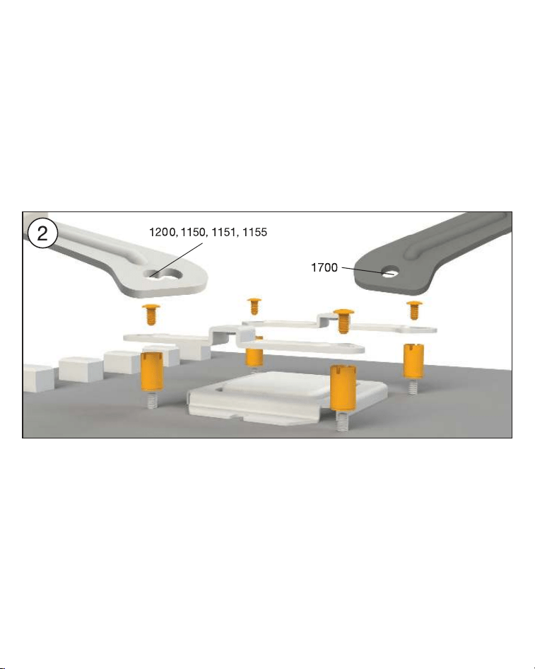
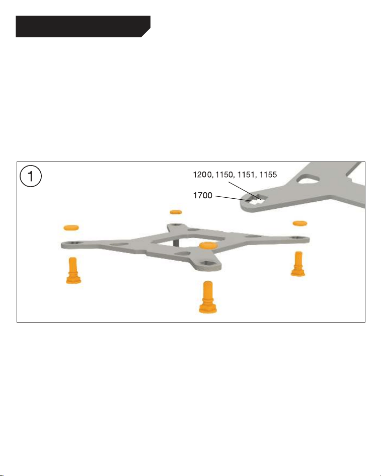
14
Installation of the mounting bridges
Screw the Intel spacer nut B onto the
previously positioned Intel backplate. Then
position, depending on your socket, the Intel
mounting brackets or Intel mounting brackets
LGA 1700 over the Intel spacer nut B and affix
these with the mounting bracket fastening
screws. You can use any cross-tip screwdriver
for this.
Installation der Montagebrücken
Schrauben Sie die Intel Gewindebolzen B auf
die zuvor platzierte Intel Backplate. Dann
positionieren Sie abhängig von Ihrem Sockel
die Intel Montagebrücken oder Intel Montage-
brücken LGA 1700 auf den Intel Gewinde-
bolzen B, um sie dann mit den Befestigungs-
schrauben für die Montagebrücken zu
fixieren. Hierzu können Sie einen üblichen
Kreuzschraubendreher nutzen.
15
3
Intel LGA 1700 / 1200 / 1150 / 1151 / 1155
Mounting the fans on the radiator
Affix the fans to the radiator with the fan
mounting screws. We recommend installation in a
push configuration. With the fans facing towards
the model name on the radiator, mount them on
the hose side.
Befestigung der Lüfter am Radiator
Befestigen Sie die Lüfter mit den Lüfter
Befestigungsschrauben am Radiator. Wir
empfehlen die Installation in einer Push Kon-
figuration. Die Lüfter, mit der Modellbezeichnung
auf den Radiator gerichtet, montieren Sie auf
der Schlauchseite.

16
Affixing the radiator to the case
Fix the radiator of Pure Loop 2 FX with the
radiator mounting screws to the case. You can
use a normal crosshead screwdriver for this.
Befestigung des Radiators am Gehäuse
Befestigen Sie den Radiator der Pure Loop 2
FX mit den Radiator Befestigungsschrauben
am Gehäuse. Hierzu können Sie einen üblichen
Kreuz-Schraubendreher verwenden.
4
17
Affixing the ARGB-PWM-Hub to the case
Mount the ARGB-PWM-Hub with the Hub
mounting screws or the double sided tissue
tape on a suitable position in your PC case. We
recommend either the rear of the mainboard
tray or a 2.5” HDD slot. Next, connect the 5V
ARGB pin and the PWM pin with the mainboard.
Then connect the SATA connector with the PSU.
Now connect the ARGB connector and the
PWM connector of the fans with the ARGB-
PWM-Hub. The connector marked RPM carries
the rpm signal of the connected device to the
Mainboard fan header.
Please find further information on the
illumination on page 26.
Befestigung des ARGB-PWM-Hub am Gehäuse
Befestigen Sie den ARGB-PWM-Hub mit den Hub-
Befestigungsschrauben oder dem doppelseitigen
Klebeband an einer geeigneten Stelle im Gehäuse.
Wir empfehlen die Rückseite des Mainboard-
Schlittens oder ein 2,5”-Laufwerksschacht.
Verbinden Sie anschließend den 5V ARGB-Stecker
und den PWM-Stecker mit dem Mainboard. Den
SATA-Anschluss verbinden Sie mit dem Netzteil.
Schließen Sie nun den ARGB-Anschluss und
PWM-Anschluss der Lüfter an den ARGB-PWM-
Hub. Der Anschluss mit der Bezeichnung RPM
gibt das Tacho-Signal des angeschlossenen
Gerätes an das Mainboard weiter.
Weitere Informationen zur Beleuchtung
finden Sie auf S. 26.
5
18
Intel LGA 1700 / 1200 / 1150 / 1151 / 1155
Mounting of the CPU block
First peel off the protective film from the underside
of the cooler. Apply thermal paste on the CPU
surface. The tube contains enough for about 1 or
2 applications.
Caution: The thermal paste supplied should not
be swallowed. If any is swallowed, drink lots of
water and urgently seek the advice of a doctor.
Store it beyond the reach of children. Avoid
contact with skin and eyes.
Montage des CPU-Blocks
Entfernen Sie zunächst die Schutzfolie von
der Unterseite des Kühlers. Tragen Sie die
Wärmeleitpaste auf die CPU-Oberfläche auf.
Der Inhalt reicht für ca.1-2 Anwendungen.
Vorsicht: Die mitgelieferte Wärmeleitpaste
ist nicht zum Verzehr geeignet. Bei Verzehr
ausreichend Wasser trinken und umgehend
einen Arzt aufsuchen. Außerhalb der Reichweite
von Kindern aufbewahren. Vermeiden Sie Haut-
und Augenkontakt.
19
Place the CPU block centrally over the Intel
mounting brackets or Intel mounting brackets
LGA 1700, such that these allow the CPU block
to be screwed down. For this you can use a
normal crosshead screwdriver. Next connect
the pump and the ARGB illumination to the
ARGB-PWM-Hub.
Please continue on page 26.
Legen Sie den CPU-Block mittig auf die Intel
Montagebrücken oder Intel Montagebrücken
LGA 1700, sodass sich der CPU-Block mit
selbigen verschrauben lässt. Hierzu können
Sie einen üblichen Kreuzschraubendreher
verwenden. Anschließend schließen Sie die
Pumpe sowie die ARGB-Beleuchtung an den
ARGB-PWM-Hub an.
Bitte lesen Sie auf S. 26 weiter.
7
20
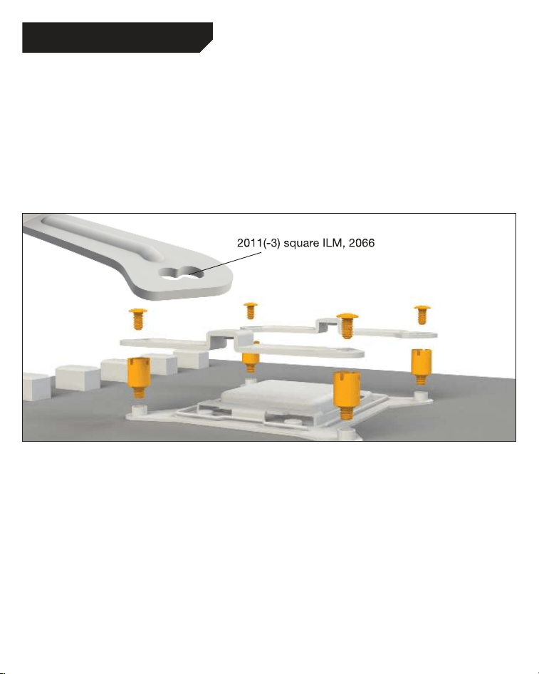
Intel LGA 2011(-3) square ILM / LGA 2066
Assembly of the cooler mounting frame
First screw the Intel spacer nuts A into the
threaded holes of the socket frame. Place
both the Intel mounting brackets over the bolts
and affix these with the fixing screws for the
mounting bridges. To do this you can use a
normal crosshead screwdriver.
Aufbau des Kühlerbefestigungsrahmens
Schrauben Sie zuerst die Intel Gewindebolzen A
in die Gewinde des Sockelrahmens. Platzieren
Sie die beiden Intel Montagebrücken auf
den Intel Gewindebolzen und schrauben Sie
diese mit den Befestigungsschrauben für die
Montagebrücken fest. Hierzu können Sie
einen üblichen Kreuz-Schraubendreher nutzen.
The following parts are needed for this:
Pure Loop 2 FX (1), Light Wings fans (2), ARGB-PWM-Hub (3), Intel mounting brackets (5), Intel spacer
nuts A (8), mounting bracket fastening screws (11), radiator mounting screws (14), fan mounting
screws (15), Hub mounting screws (16), thermal paste (18), double sided tissue tape (21)
Es werden folgende Bauteile benötigt:
Pure Loop 2 FX (1), Light Wings Lüfter (2), ARGB-PWM-Hub (3), Intel Montagebrücken (5),
Intel Gewindebolzen A (8), Befestigungsschrauben für die Montagebrücke (11), Radiator
Befestigungsschrauben (14), Lüfter Befestigungsschrauben (15), Hub-Befestigungsschrauben (16),
Wärmeleitpaste (18), Doppelseitiges Klebeband (21)
21
Befestigung der Lüfter am Radiator
Befestigen Sie die Lüfter mit den Lüfter
Befestigungsschrauben
am Radiator. Wir
empfehlen die Installation in einer Push Kon-
figuration. Die Lüfter, mit der Modellbezeichnung
auf den Radiator gerichtet, montieren Sie auf
der Schlauchseite.
Mounting the fans on the radiator
Affix the fans to the radiator with the fan
mounting screws. We recommend installation
in a push configuration. With the fans facing
towards the model name on the radiator, mount
them on the hose side.
2
22
Intel LGA 2011(-3) square ILM / LGA 2066
Affixing the radiator to the case
Fix the radiator of Pure Loop 2 FX with the
radiator mounting screws to the case. You can
use a normal crosshead screwdriver for this.
Befestigung des Radiators am Gehäuse
Befestigen Sie den Radiator der Pure Loop 2
FX mit den Radiator Befestigungsschrauben
am Gehäuse. Hierzu können Sie einen üblichen
Kreuz-Schraubendreher verwenden.
3
23
Affixing the ARGB-PWM-Hub to the case
Mount the ARGB-PWM-Hub with the Hub
mounting screws or the double sided tissue
tape on a suitable position in your PC case. We
recommend either the rear of the mainboard
tray or a 2.5” HDD slot. Next, connect the 5V
ARGB pin and the PWM pin with the mainboard.
Then connect the SATA connector with the PSU.
Now connect the ARGB connector and the
PWM connector of the fans with the ARGB-
PWM-Hub. The connector marked RPM carries
the rpm signal of the connected device to the
Mainboard fan header.
Please find further information on the
illumination on page 26.
Befestigung des ARGB-PWM-Hub am Gehäuse
Befestigen Sie den ARGB-PWM-Hub mit den Hub-
Befestigungsschrauben oder dem doppelseitigen
Klebeband an einer geeigneten Stelle im Gehäuse.
Wir empfehlen die Rückseite des Mainboard-
Schlittens oder ein 2,5”-Laufwerksschacht.
Verbinden Sie anschließend den 5V ARGB-Stecker
und den PWM-Stecker mit dem Mainboard. Den
SATA-Anschluss verbinden Sie mit dem Netzteil.
Schließen Sie nun den ARGB-Anschluss und
PWM-Anschluss der Lüfter an den ARGB-PWM-
Hub. Der Anschluss mit der Bezeichnung RPM
gibt das Tacho-Signal des angeschlossenen
Gerätes an das Mainboard weiter.
Weitere Informationen zur Beleuchtung
finden Sie auf S. 26.
4
24
Montage des CPU-Blocks
Entfernen Sie zunächst die Schutzfolie von
der Unterseite des Kühlers. Tragen Sie die
Wärmeleitpaste auf die CPU-Oberfläche auf. Der
Inhalt reicht für ca. 1-2 Anwendungen.
Vorsicht: Die mitgelieferte Wärmeleitpaste
ist nicht zum Verzehr geeignet. Bei Verzehr
ausreichend Wasser trinken und umgehend einen
Arzt aufsuchen. Außerhalb der Reichweite von
Kindern aufbewahren. Vermeiden Sie Haut- und
Augenkontakt.
Mounting of the CPU block
First peel off the protective film from the
underside of the cooler. Apply thermal paste on
the CPU surface. The tube contains enough for
about 1 or 2 applications.
Caution: The thermal paste supplied should
not be swallowed. If any is swallowed, drink
lots of water and urgently seek the advice of a
doctor. Store it beyond the reach of children.
Avoid contact with skin and eyes.
25
Place the CPU block centrally over the Intel
mounting brackets, such that these allow the
CPU block to be screwed down. For this you
can use a normal crosshead screwdriver. Next
connect the pump and the ARGB illumination to
the ARGB-PWM-Hub.
Legen Sie den CPU-Block mittig auf die Intel
Montagebrücken, sodass sich der CPU-Block
mit selbigen verschrauben lässt. Hierzu können
Sie einen üblichen Kreuz-Schraubendreher
verwenden. Anschließend schließen Sie die
Pumpe sowie die ARGB-Beleuchtung an den
ARGB-PWM-Hub an.
6
Intel LGA 2011(-3) square ILM / LGA 2066
26
Synchronization of ARGB illumination with
the motherboard
Pure Loop 2 FX enables you to synchronize the
ARGB illumination of up to 6 ARGB devices with
the motherboard by the ARGB-PWM-Hub. When
the ARGB-PWM-Hub is mounted into the case,
the ARGB illumination is being controlled by the
motherboard software.
Warning: The ARGB connector may only be
connected to a 5V ARGB header.
Synchronisation der ARGB Beleuchtung
mit dem Mainboard
Die Pure Loop 2 FX bietet Ihnen die Möglichkeit,
die ARGB-Beleuchtung von bis zu 6 ARGB-
Geräten über den ARGB-PWM-Hub mit Ihrem
Mainboard zu synchronisieren. Die Steuerung der
ARGB-Beleuchtung ist über die Bediensoftware
des Mainboards geregelt, wenn der ARGB-
PWM-Hub im Gehäuse montiert ist.
Achtung: Der ARGB-Anschluss darf nur an
einem 5V ARGB-Anschluss angeschlossen
werden.
ILLUMINATION / BELEUCHTUNG
27
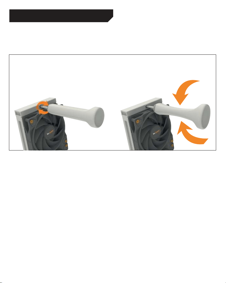
Refilling the system
Topup the system after about two years of use.
In order to do this, first detach the radiator from
the case. The filling port is on the opposite end
of the hoses. Open this as well as the bottle with
cooling fluid. Rotate the bottle into the filling
port. Hold the radiator so that the filling port is
at the highest level with the bottle upended over
it. Then lightly squeeze the bottle. Repeat this
until no further air bubbles appear in the bottle.
CAUTION: The coolant fluid supplied is not a
drink. Keep out of reach of children. Be careful
not to get it on your eyes or skin. If it does adhere,
rinse immediately with water.
Nachfüllen des Systems
Füllen Sie das System nach ca. zwei Jahren
Gebrauch nach. Zu diesem Zweck demontieren
Sie den Radiator vom Gehäuse. Der Nachfüll-
Port liegt auf der gegenüberliegenden Seite
der Schläuche. Öffnen Sie sowohl diesen als
auch die Flasche mit Kühlflüssigkeit. Drehen
Sie diese in den Refill Port. Halten den Radiator
so, dass der Refill Port der höchste Punkt ist
und die Flasche kopfüber steht. Anschließend
drücken Sie die Flasche leicht. Wiederholen Sie
diesen Vorgang, bis keine Luftbläschen zurück
in die Flasche aufsteigen.
ACHTUNG: Die mitgelieferte Kühlflüssigkeit ist
nicht zum Verzehr geeignet. Außer Reichweite
von Kindern aufbewahren. Vermeide Haut- und
Augenkontakt. Bei Kontakt sofort mit Wasser
ausspülen.
REFILLING THE SYSTEM / NACHFÜLLEN DES SYSTEMS
28
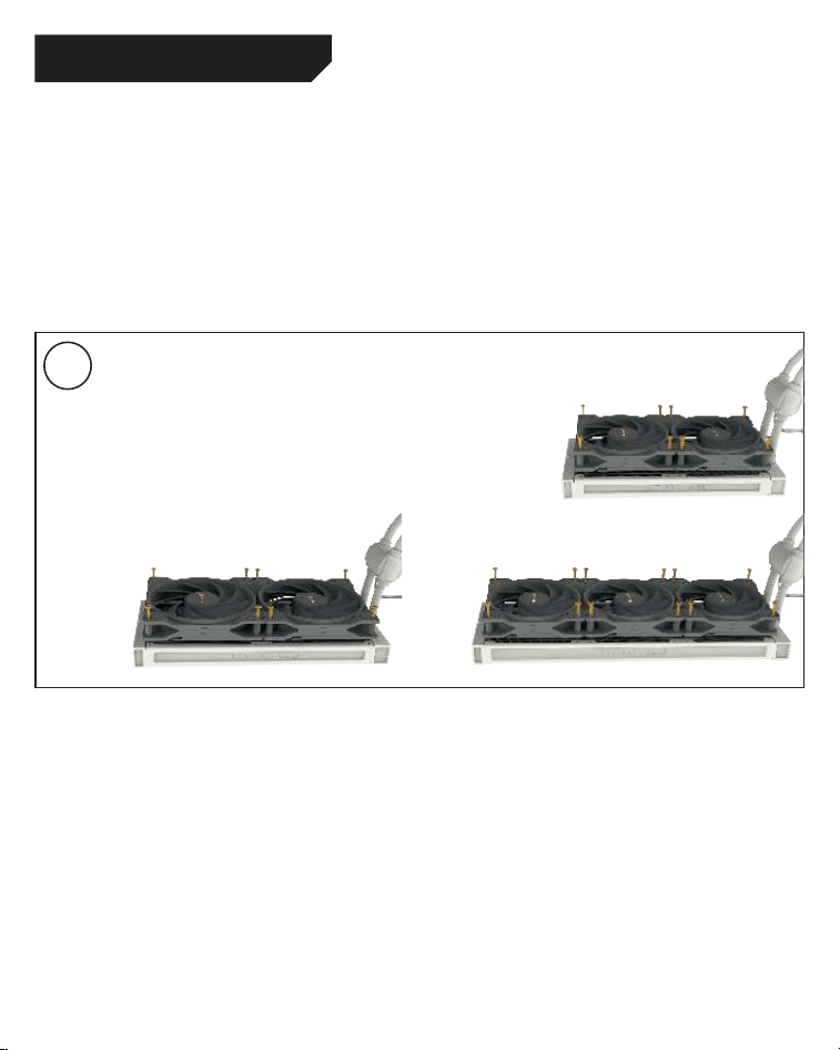
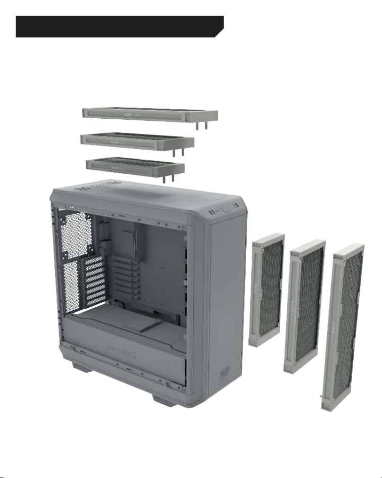
RECOMMENDED INSTALLATION / EMPFOHLENE EINBAUPOSITION

29
Insufficient cooling performance
■
Ensure the CPU block is mounted as described
in the instructions. Use only the mounting
equipment supplied with the unit.
■
Please operate the lighting only with 5 volts.
No voltage regulator should be used, because
this can damage the device.
■
Have you applied too much or too little thermal
paste? It is sufficient when it thinly covers the
CPU.
■
After a drop in coolant is apparent, it is
advisable to top up the coolant level to
maintain optimum cooling performance. For
the correct way to top up the coolant, refer to
the installation instructions.
■
Please ensure that the airflow of the fans is
not restricted, to guarantee their maximum
performance.
■
Check that sufficient room is allocated to
the radiator, so it is able to draw in sufficient
cooling air and expel the warmed air.
Produces more noise
■
Check the coolant level and if necessary top
it up. The right way to do this is described in
the installation instructions. When the coolant
level is too low, it leads to more noise and can
damage the device.
■
The radiator must be mounted in a suitable
position in the case to prevent vibration and
turbulence in the airflow. Please also note any
advice given by the manufacturer of the case.
■
Make sure that no tubes or cables come into
contact with fans in the case. Bubbles of air
may have become trapped in the pump’s
impeller during transportation. It may be
possible to free the impeller by repeated
switching on and/or loading cycles.
Painted surfaces of the radiator
■
The Pure Loop all-in-one water cooler uses an
aluminum radiator, which is originally silver in
color. The radiator is lightly tinted with black
paint, which from certain perspectives might
not be entirely opaque. This outer paint cover
does not affect the cooling performance in any
way.
■
The Pure Loop all-in-one water cooler is
a cooling unit intended for the cooling of
processors and made solely for that purpose.
If you plan to open up or modify its closed
system we are no longer able to guarantee
its functionality or cooling performance in
any way. Please only allow authorized service
technicians to undertake repairs. Opening
the device besides of the refillport voids the
warranty.
■
Should you experience any other problems
with the water cooler, please get in touch
with our service department. You will find
our contact details in the manufacturer’s
information section.
TROUBLESHOOTING

30
Unzureichende Kühlleistung
■
Bitte montieren Sie den CPU-Block wie im
Handbuch beschrieben. Nutzen Sie dazu
ausschließlich das beiliegende Montage-
material.
■
Kontrollieren Sie die Kabelverbindungen
von Pumpe und Lüftern. Bitte betreiben Sie
die Beleuchtung bei 5 Volt. Es darf keine
Spannungsregulierung zum Einsatz kommen,
da das Gerät sonst Schaden nehmen kann.
■
Haben Sie zu viel – oder keine – Wärmeleitpaste
aufgetragen? Es genügt, wenn die CPU mit
einer dünnen Schicht leicht bedeckt ist.
■
Bei merklichem Flüssigkeitsverlust empfiehlt
es sich zum Aufrechterhalten der Kühlleistung
die Kühlflüssigkeit nachzufüllen. Die korrekte
Handhabung entnehmen Sie bitte der
Installationsanleitung.
■
Bitte überprüfen Sie, ob die Lüfter zu stark
gedrosselt sind. Beide Lüfter müssen
ungedrosselt betrieben werden, um die volle
Leistungsfähigkeit zu gewährleisten.
■
Bitte prüfen Sie, ob der Radiator ausreichend
Platz hat, um kühle Luft anzusaugen und die
erwärmte Luft abzugeben.
Stark erhöhte Lautstärke
■
Kontrollieren Sie den Flüssigkeitskreislauf
und füllen Sie ihn ggf. nach. Ein zu geringer
Flüssigkeitsstand kann zu einer erhöhten
Lautstärke und zum Defekt des Gerätes führen.
■
Der Radiator muss an einer geeigneten
Stelle montiert sein, um Schwingungen des
Gehäuses sowie starke Luftverwirbelungen
zu vermeiden. Bitte beachten Sie hierzu die
Angaben Ihres Gehäuseherstellers.
■
Bitte achten Sie darauf, dass Schläuche
und Kabel nicht in Berührung mit Lüftern im
Gehäuse kommen. Beim Transport könnten
sich Lüfterbläschen am Impeller der Pumpe
verfangen haben, durch mehrmalige Einschalt-
und/oder Lastzyklen könnte der Impeller frei
werden
Verfärbte Oberfläche des Radiators
■
Die Pure Loop All-In-One Wasserkühlung nutzt
einen Aluminiumradiator, der im Ursprung
einen Silber-Ton hat. Die Radiatoren wurden
oberflächlich mit schwarzer Farbe versehen,
die aus bestimmten Perspektiven nicht
blickdicht sein kann. Durch die äußerliche
Färbung wird die Kühlleistung in keinster
Weise beeinflusst.
■
Bei den Pure Loop All-In-One Wasserkühlungen
handelt es sich um Kühlungseinheiten, die
zur Kühlung von Prozessoren vorgesehen
und gefertigt wurden. Sollten Sie vorhaben
den Kühlkreislauf zu öffnen oder zu
modifizieren, können wir keinerlei Garantie
für die Funktionalität sowie die zu erwartende
Kühlleistung übernehmen. Bitte lassen
Sie Reparaturen nur von autorisiertem
Fachpersonal durchführen! Ein Öffnen des
Gerätes abseits vom Refill Port am Radiator
führt zum Garantieverlust.
■
Sollten Sie darüber hinaus Probleme mit Ihrer
Wasserkühlung haben wenden Sie sich bitte
an unseren Service. Die Kontaktinformationen
finden Sie im Abschnitt “Herstellerangaben”.
FEHLERBEHEBUNG

31
I. APPLICABILITY
This non-transferable warranty is applicable to
newly purchased, previously unopened be quiet!
products and is enforceable by only the original
consumer purchaser. Proof of purchase is required
for warranty service, so should be retained. be quiet!
does not provide warranty registration services.
II. WARRANTY PERIOD
For eligible products, parts and labor are warranted
for the applicable warranty period from the date of
purchase. The applicable warranty period varies
by product model, and is identified in your user
documentation, on the product package, or as
listed below. Should any of these warranty periods
differ, the longest specified warranty period will
apply. Replaced products will be warranted for the
remainder of the original warranty period or thirty
days, whichever is longer.
III. EXCLUSIONS
The following are not covered by the warranty:
1. Normal wear and tear.
2. Any product which has been modified without
permission from be quiet!, or on which the serial
number or warranty sticker has been defaced,
modified, or removed.
3. Damage, deterioration or malfunction resulting
from: Accident, abuse, misuse or improper use,
neglect, connection to an improper voltage
source, unauthorized product modification, or
failure to follow instructions included with the
product. Fire, water, lightning, or other acts of
nature. Repair or attempted repair by anyone not
authorized by be quiet!. Shipping or transport
damage (claims must be made with the carrier).
Any other cause which does not relate to a defect
in materials or manufacturing workmanship.
4. Cartons, cases, batteries, cabinets, tapes,
accessories or other consumables used with this
product.
5. be quiet!, Inc. does not warrant that this
product will meet your requirements. It is your
responsibility to determine the suitability of this
product for your purpose.
6. Removal or installation charges.
7. Shipping charges.
8. Any incidental charges.
IV. EXCLUSION OF DAMAGES
be quiet!‘s sole obligation and liability under this
warranty is limited to the repair or replacement of
a defective product at its option. be quiet! shall not,
in any event, be liable for any special, incidental,
indirect, or consequential damages whatsoever,
including but not limited to loss of profits, revenue,
or data (whether direct or indirect), damages
resulting from interruption of service and loss
of business, or for liability in tort relating to this
product or resulting from its use
or possession, even if be quiet! has been advised
previously of the possibility of such damages.
V. LIMITATIONS OF IMPLIED WARRANTIES
There are no other warranties, expressed or implied,
including but not limited to those of merchantability
or fitness for a particular purpose. The duration of
implied warranties is limited to the warranty length
specified in Paragraph II.
VI. LOCAL LAW AND YOUR WARRANTY
This warranty gives you specific legal rights. You
may also have other rights granted under local law.
These rights may vary.
VII. NO OTHER WARRANTY
No be quiet! employee, dealer, or other agent is
authorized to make any modification, extension, or
addition to this warranty.
VIII. TO OBTAIN TECHNICAL SUPPORT OR
WARRANTY SERVICE
Please see your product owner’s manual or visit the
Online Support section at www.bequiet.com
LIMITED WARRANTY

bequiet.com
