
BULLETIN NO.
54-26-2960
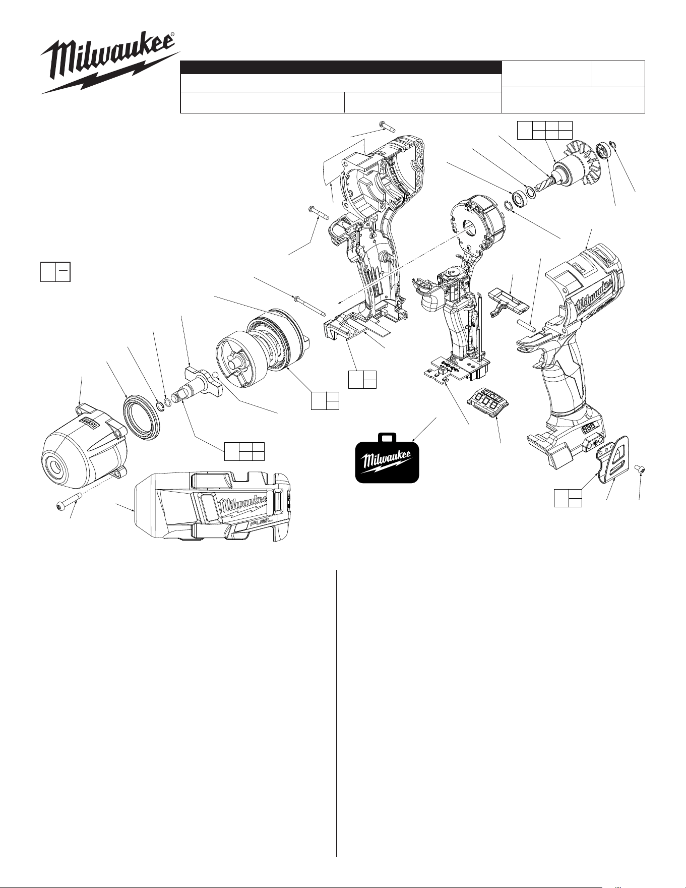
SERVICE PARTS LIST
FIG. PART NO. DESCRIPTION OF PART NO. REQ.
1 06-82-2366 M5 x 26.5mm Pan Hd. ST T-25 Screw (4)
3 45-88-0101 Plastic Gearcase Washer (1)
4 44-90-1050 Friction Ring for 3/8" Anvil (1)
5 34-40-1885 O-Ring for 3/8" Anvil (1)
6 --------------- 3/8" Square (Friction Ring) Anvil (1)
7 02-02-7010 7/32" Steel Ball (1)
18 34-40-0067 O-Ring (1)
24 02-04-0330 Ball Bearing (1)
FIG. PART NO. DESCRIPTION OF PART NO. REQ.
25 45-88-3071 Washer (1)
26 --------------- Armature (1)
27 02-04-1930 Ball Bearing (1)
28 34-60-2493 Retaining Ring (1)
29 06-82-2367 M3 x 38mm Pan Hd. ST T-10 Screw (2)
30 06-82-2368 M3.5 x 16mm Pan Hd. ST T-10 Screw (6)
31 --------------- Housing Cover - Right Housing Halve (1)
32 06-65-0465 Pin (1)
33 06-82-2369 M3.5 x 22mm Pan Hd. ST T-10 Screw (1)
35 --------------- Housing Support - Left Housing Halve (1)
36 --------------- Belt Clip (1)
37 06-82-0130 6-32 x .275 Pan Hd. T-15 Screw (1)
38 42-42-0018 Forward/Reverse Shuttle (1)
46 14-38-0006 Gearcase Assembly w/ Bushing (1)
47 14-73-0009 3/8" Square Friction Ring Anvil Assy. (1)
48 14-30-0018 Impact Assembly (1)
49 14-20-0099 Electronics Assembly (1)
50 16-01-2860 Rotor Assembly (1)
51 31-44-0069 Housing Assembly (1)
52 45-24-2656 Speed Selector Assembly (1)
53 42-70-0059 Belt Clip Assembly (1)
54 12-20-2860 Service Nameplate (1)
56 42-55-2860 Carrying Case (1)
59 34-60-0011 Retaining Ring (1)
62 49-16-2861 Rubber Boot, Accessory (1)
CATALOG NO. 2852-20
REVISED BULLETIN
SPECIFY CATALOG NO. AND SERIAL NO. WHEN ORDERING PARTS
M18™ FUEL™ 3/8" Square Impact Wrench
STARTING
SERIAL NO.
DATE
Mar. 2018
WIRING INSTRUCTION
J73A
SEE PAGE 2
EXAMPLE:
Component Parts (Small #)
Are Included When Ordering
The Assembly (Large #).
0
00
MILWAUKEE TOOL
l
www.milwaukeetool.com
13135 W. Lisbon Road, Brookeld, Wisc. 53005
Drwg. 1
FIG. LUBRICATION
Use Type 'J' Grease, No. 49-08-4220 (1 lb. can)
Service grease may not be compatable with grease used
during manufacturing. 90-95% of the old grease must be
removed prior to any new grease being added.
3 Coat plastic washer prior to installing in gearcase assembly.
6,7 Apply grease to shaft of anvil. Place grease in hole at back of
anvil. Coat steel ball with grease and place in hole.
26 Place grease to the pinion area of rotor, being sure to cover all
of gear teeth.
46 Apply a coat of grease to bushing ID in gearcase assembly.
48 Service impacting assembly comes pre-lubricated.
54
56
18
29(2x)
33(1x)
31
38
32
35
24
25
26
28
27
30(6x)
49
52
37
36
53
36
37
51
31
35
48
18
47
4 5
6 7
7
50
24 25 26
27 28 59
1(4x)
46
3
4
5
6
59
62
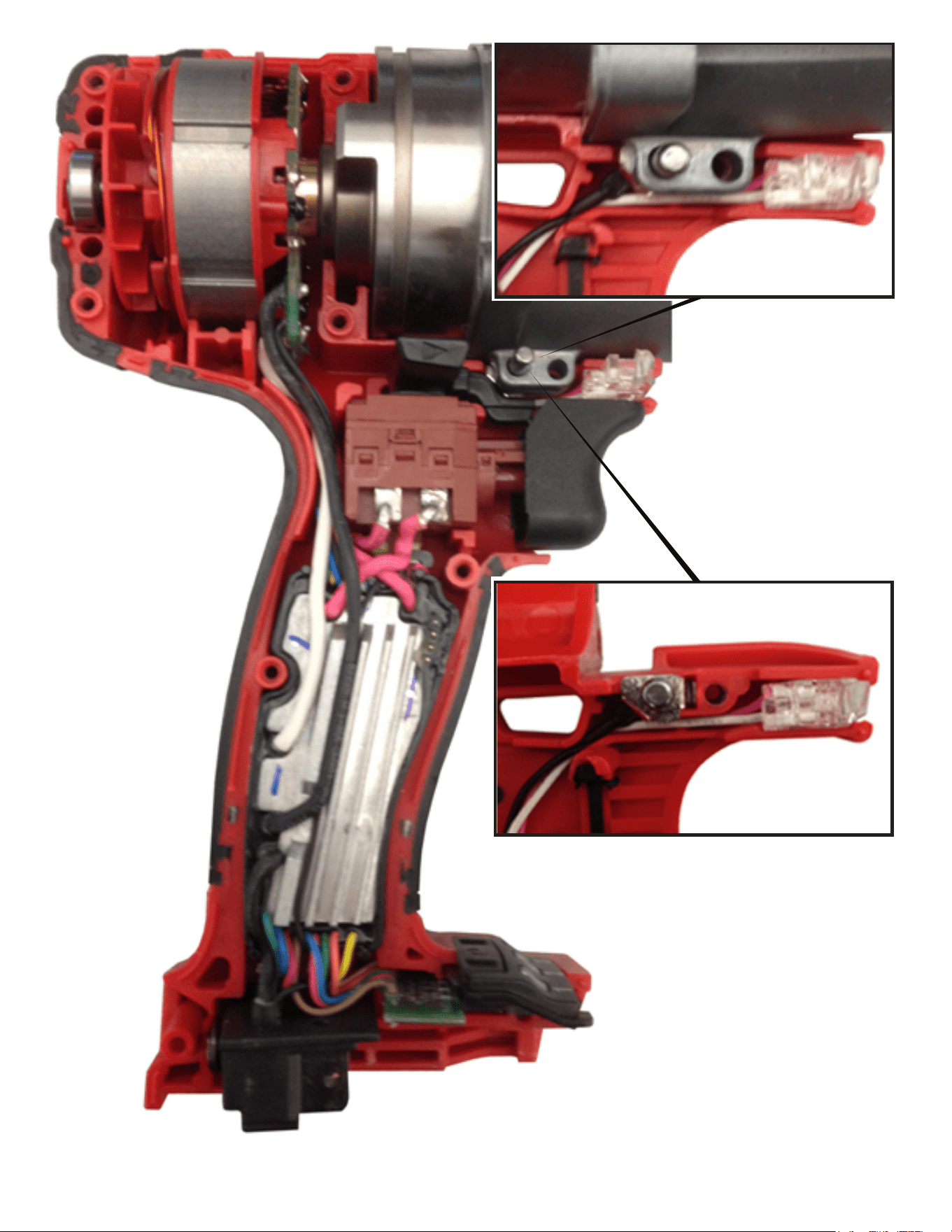
Detail shown with Switch and
Fwd/Rev Shuttle removed to
illustrate LED wires and Ground
wire trapping and routing.
Detail shown with Switch, Fwd/Rev
Shuttle, Impact Assembly and Gear
Case removed to illustrate the
Grounding Terminal placement over
the Pin.
As an aid to reassembly, take note
of wire routing and position in wire
guides and traps while dismantling
tool. Be careful and avoid pinching
wires between handle halves when
assembling.
Check for proper switch and shuttle
functionality prior to securing
handle halves._