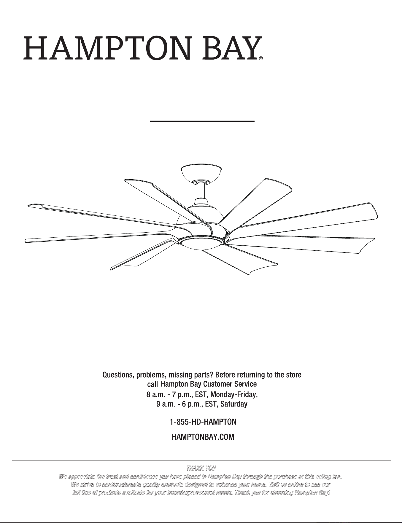
USE AND CARE GUIDE
THANK YOU
We appreciate the trust and condence you have placed in Hampton Bay through the purchase of this celing fan.
We strive to continualcreate guality products designed to enhance your home. Visit us online to see our
full line of products available for your homeimprovement needs. Thank you for choosing Hampton Bay!
SKU: #xxxxx
Model: #SW23050
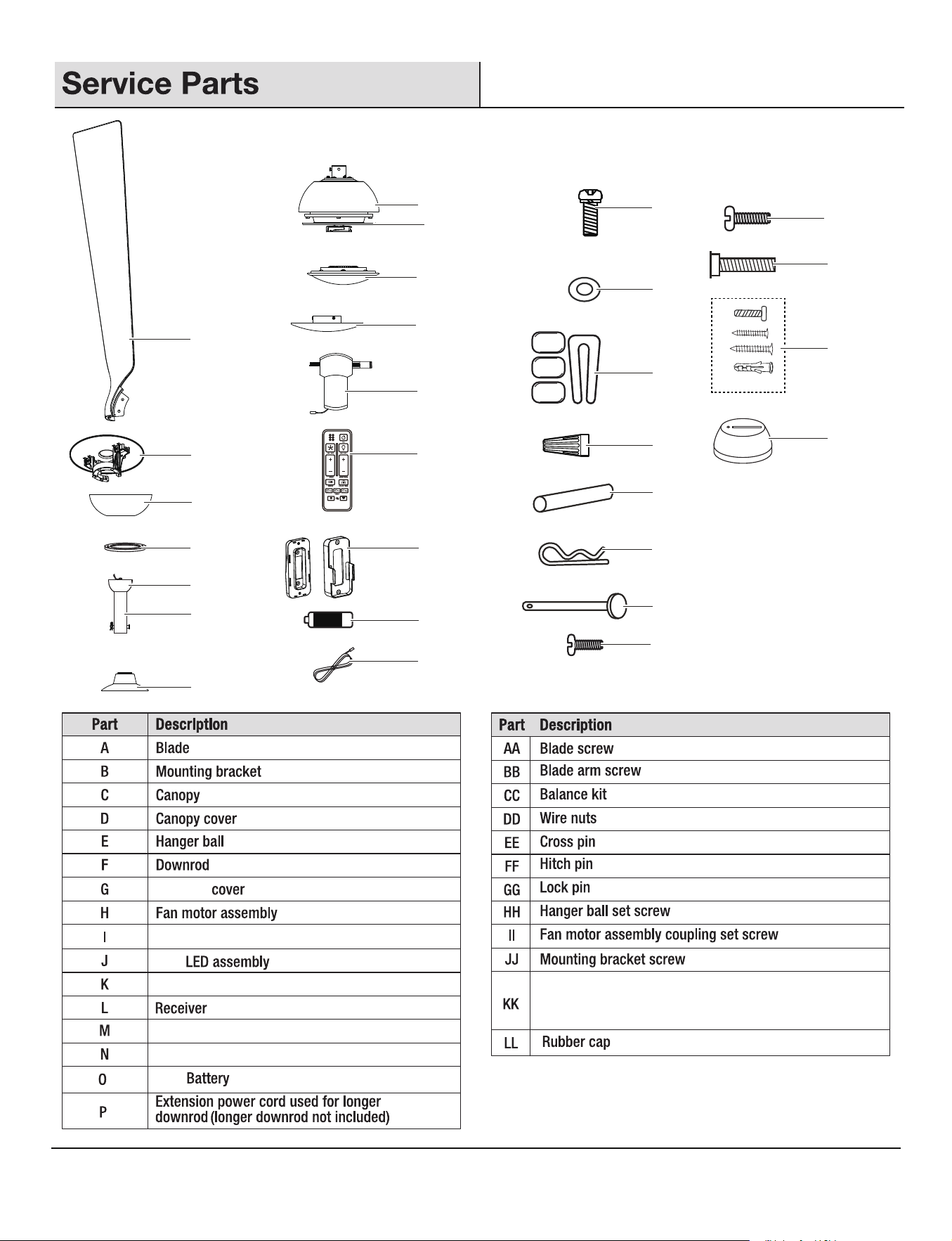
xxxx LED 60 INCH CEILING FAN
20
21
22
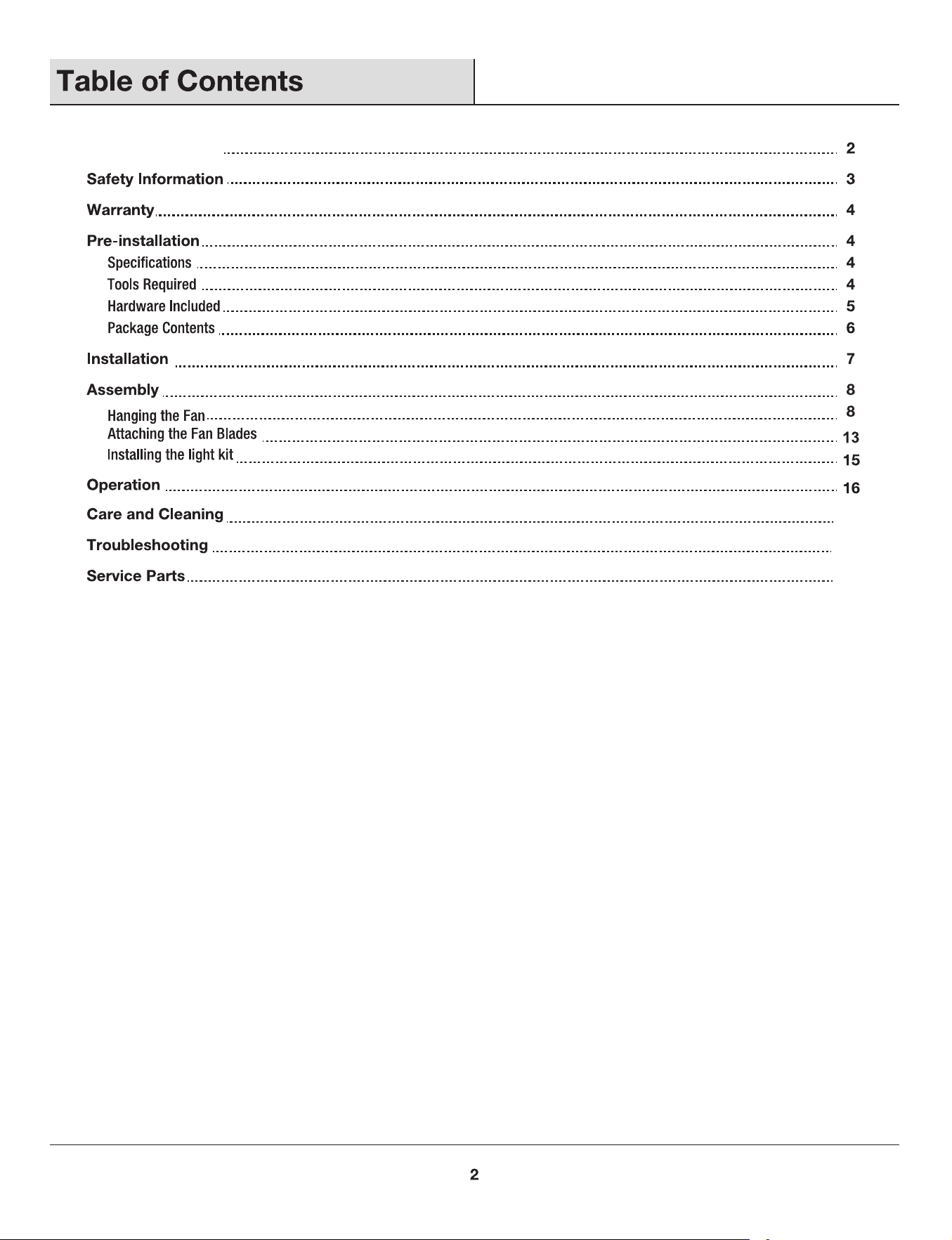
Table of Contents
xxx
xxxxxxx
Summer Wind International Ltd.
or, at our option,
gives
xxx kg
(xxx lb)
xxx '
xxx xxx xxx xxx
xxx xxx xxx xxx
xxx xxx xxx xxx
xxx kg
(xxx lb)
60 in.
(xxx m)
Metal washer
1 set
1 set
Remote wall cradle hardware pack (ST3.5*13mm screw -2pcs,
ST3.0*18mm screw-2pcs, #6/32*13mm screw-2pcs, anchor -2pcs)
3+1 spare
16+1 spare
16+1 spare
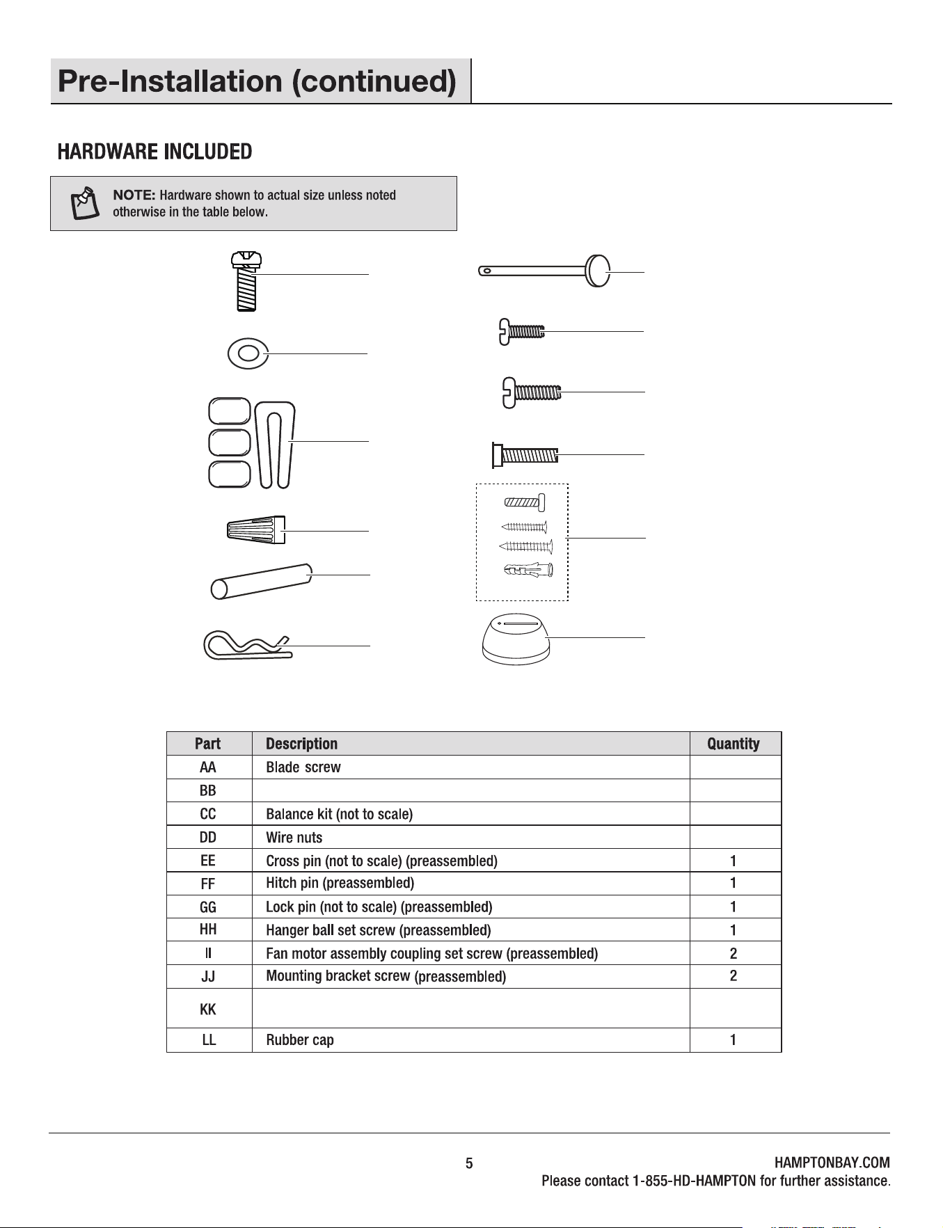
AA
BB
CC
DD
EE
FF
GG
HH
II
JJ
KK
LL
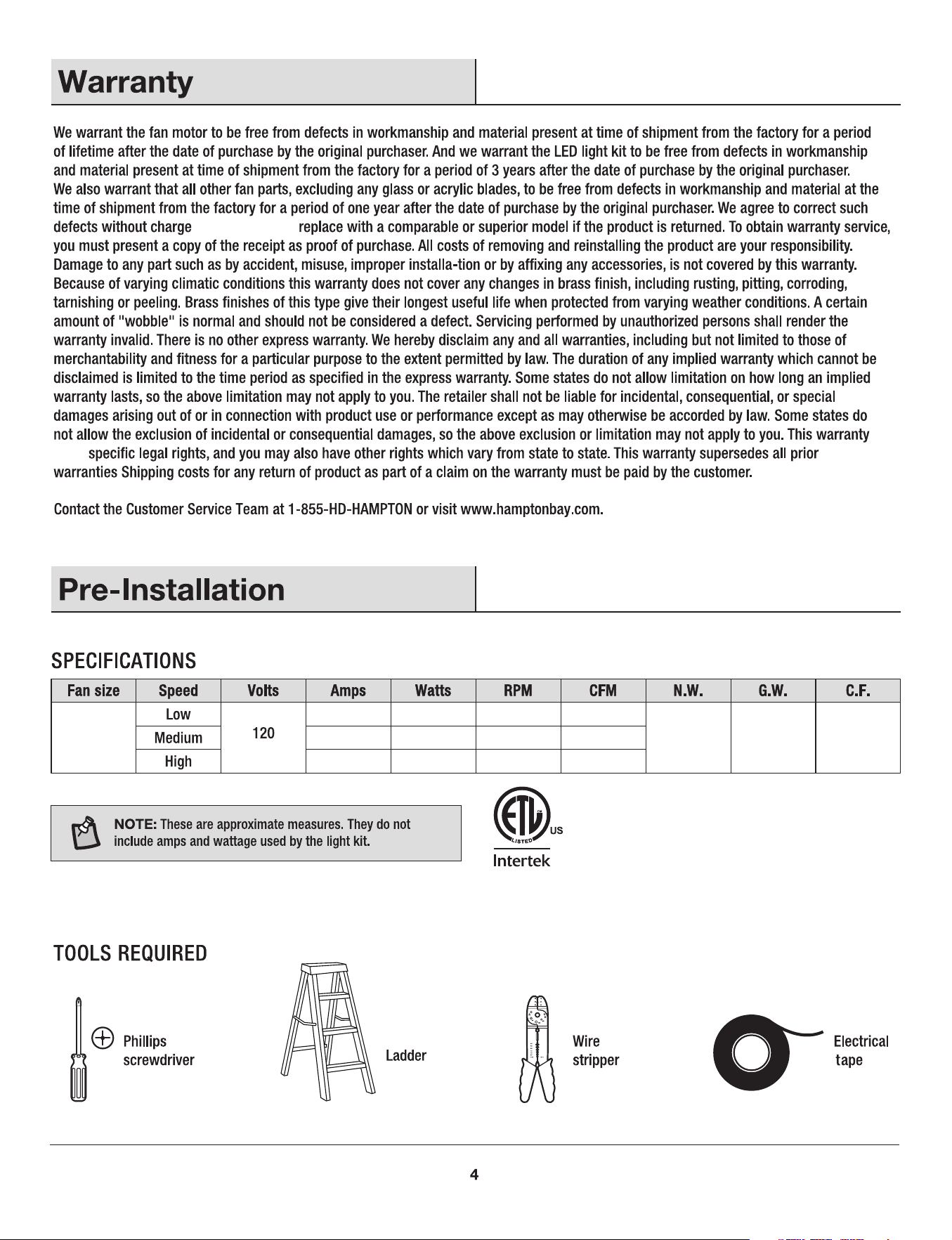
1.5V
18W
1.5V
8
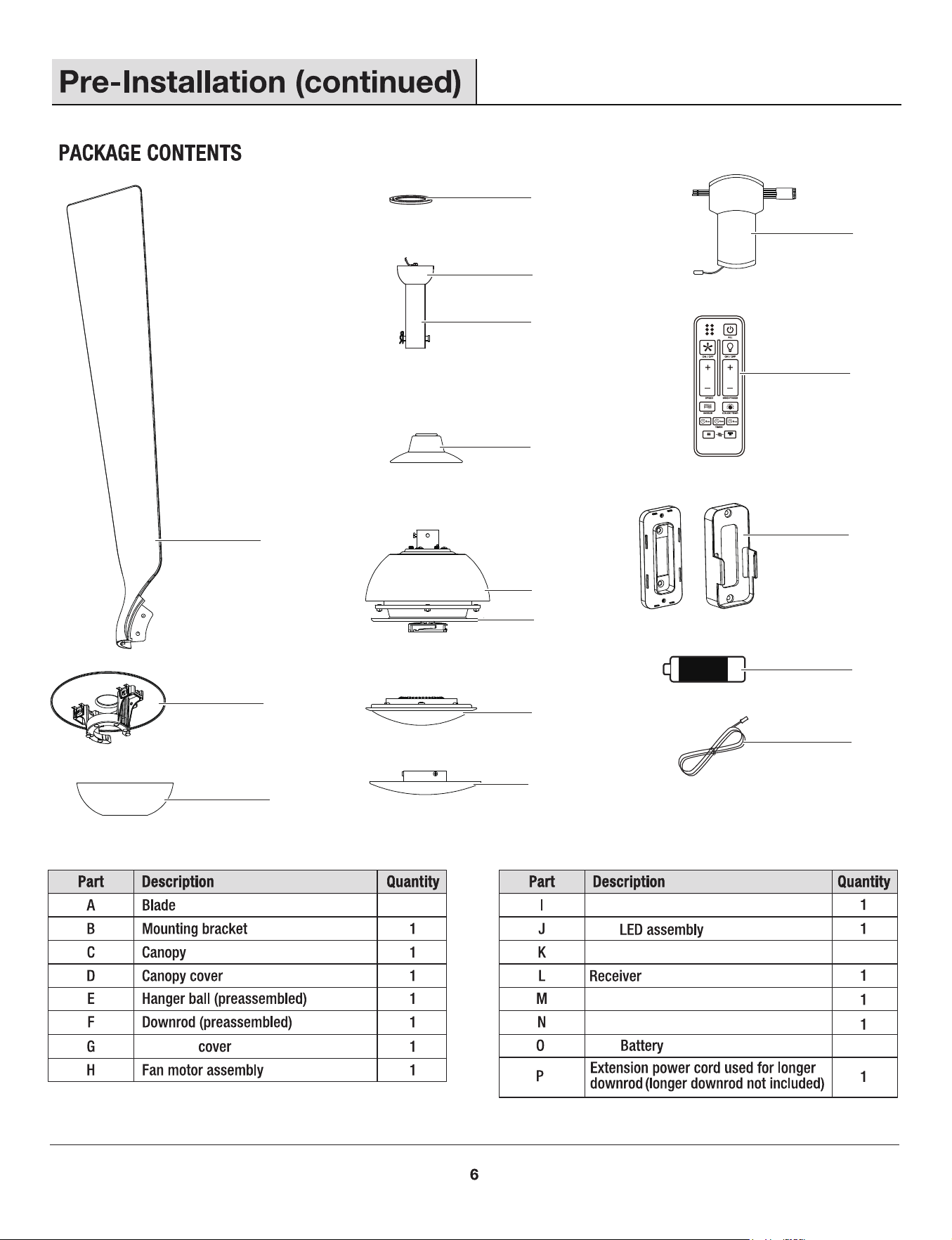
Remote control
2
Remote wall cradle
Metal shade
1
A
D
E
F
G
H
I
J
K
L
M
N
O
P
Coupling
Flywheel (preassembled)
6
SUMMER
WINTER
FAN DIRECTION
HOLD 3 SEC.
A
B
C
1
1
2
3
1
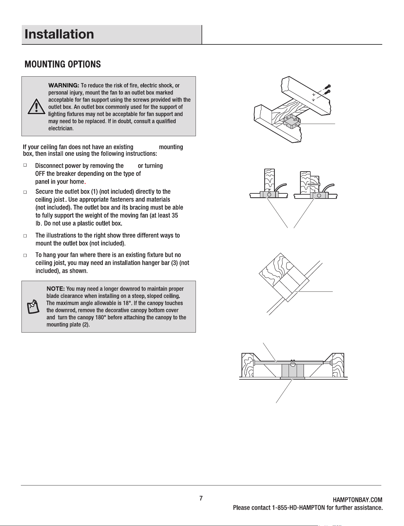
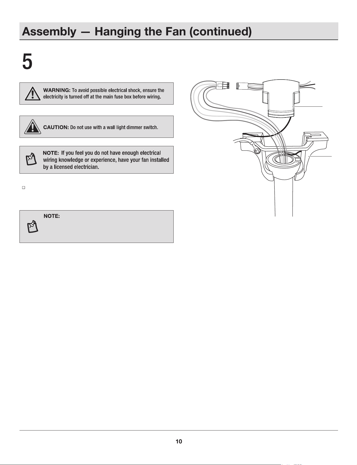
UL Listed
fuse
electrical
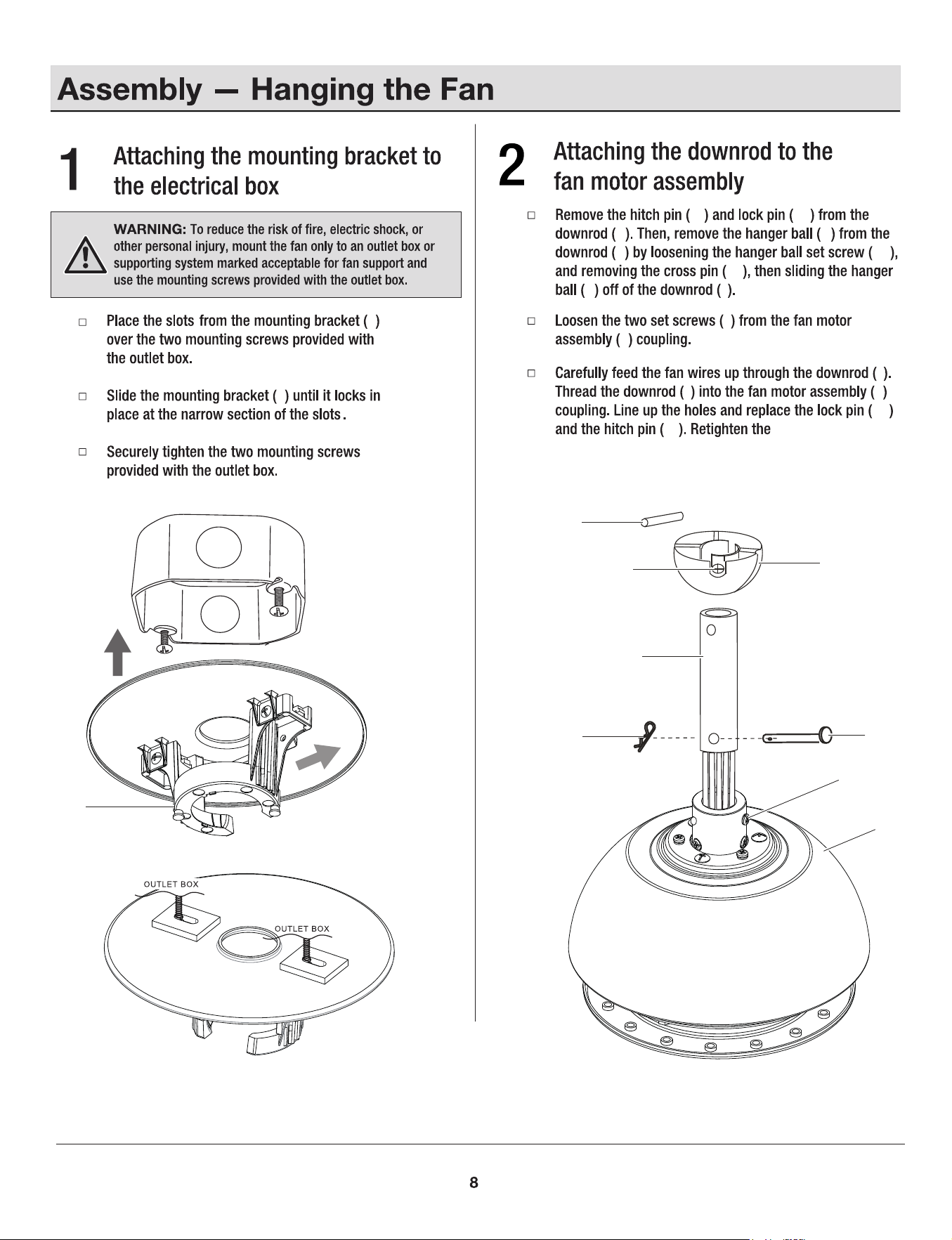
fan motor assembly
coupling set screws (II).
B
HH
H
B
B
EE
E
HH
F
GG
FF
II
H
FF
F
E
F
F
F
GG
FF
EE
E F
II
H
GG
B
H
H
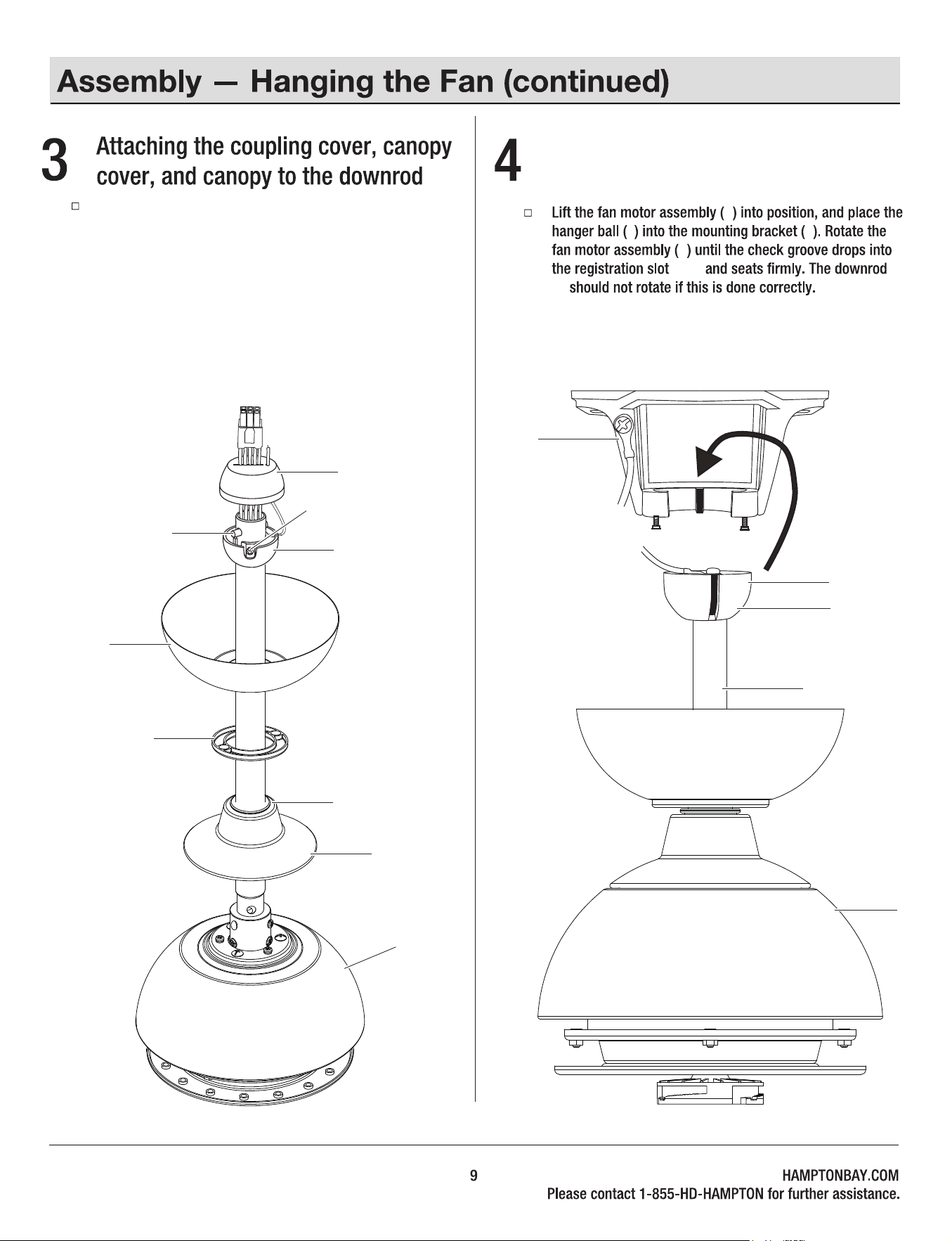
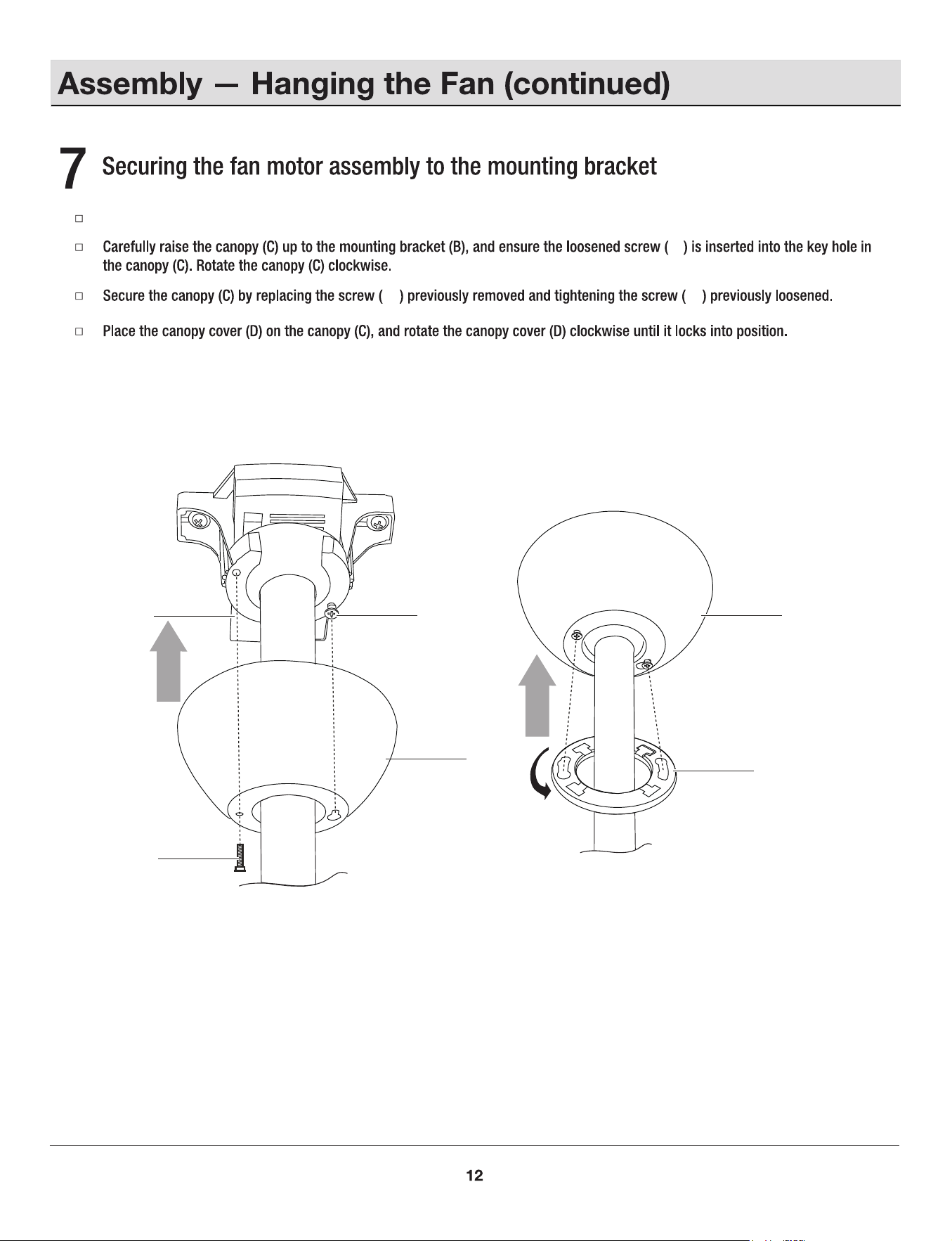
Hanging the fan motor assembly
to the mounting bracket
MM
B
E
E
(MM)
(F)
Slip the coupling cover (G), canopy cover (D), and canopy
(C) onto the downrod (F). Carefully reinstall the hanger
ball (E) onto the downrod (F), and ensure that the cross pin
(EE) is in the correct position, the set screws (HH) are tight,
and the wires are not twisted. Carefully feed fan wires
through the holes in the rubber cap (LL) and make the
rubber cap (LL) cover the hanging ball (E).
C
H
EE
HH
E
D
LL
F
G
F
H
Insert the receiver (L) into the mounting bracket (B) with the
ventilated side facing down.
Wires coming from the downrod and the wires
coming from the power source need to be positioned on
the same side when inserting the receiver through the
mounting bracket.
Installing the receiver
L
B
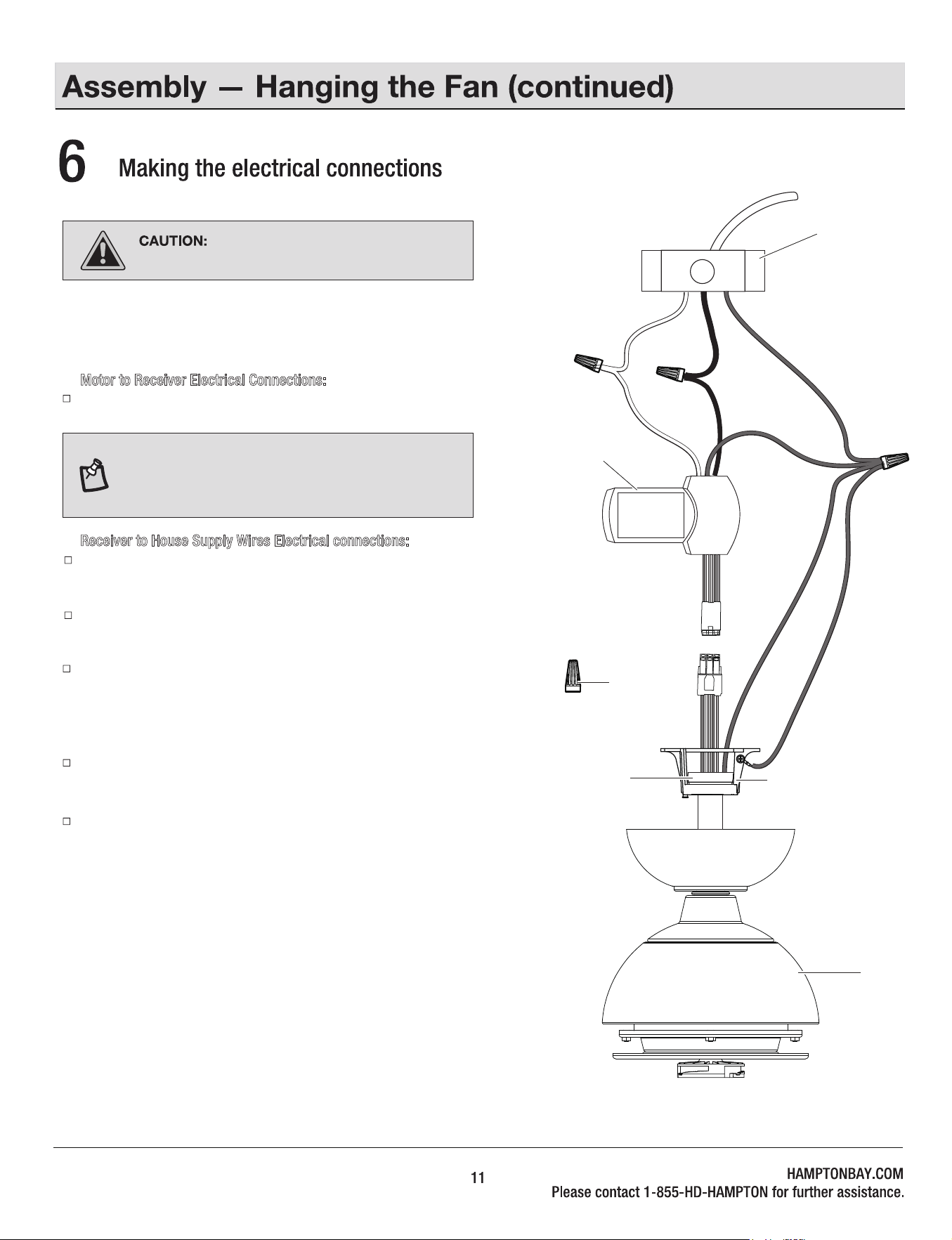
If your outlet box has a GROUND wire (Green or Bare Copper), connect
this wire to the Hanger Ball and Hanger Bracket and receiver Ground
wires. If your outlet box does not have a Ground Wire, then connect the
Hanger Ball and Hanger Bracket and Receiver Ground Wire together.
Secure wire connection with the plastic wire nuts (DD) provided. Especially,
for the ground wires, please use bigger wire nut (DD) provided.
After all splices are made, check to make sure there are no loose strands.
Follow the steps below to connect the fan to your house supply wires.
Secure the wire nuts by wrapping the connection with electrical tape.
Motor to Receiver Electrical Connections:
Connect the male connector from the motor to the female connector
from the receiver (L).
Receiver to House Supply Wires Electrical connections:
Connect the WHITE wire (Neutral) from the outlet box to the WHITE wire
marked “AC in N” from the receiver.
Connect the BLACK wire (Hot) from the outlet box to the BLACK wire
marked “AC in L” from the receive.
NOTE: Fan must be installed from a maximum distance
of 40 feet (12.2 m) from the transmitting unit for proper
signal transmission between the transmitting unit and
the fan's receiving unit.
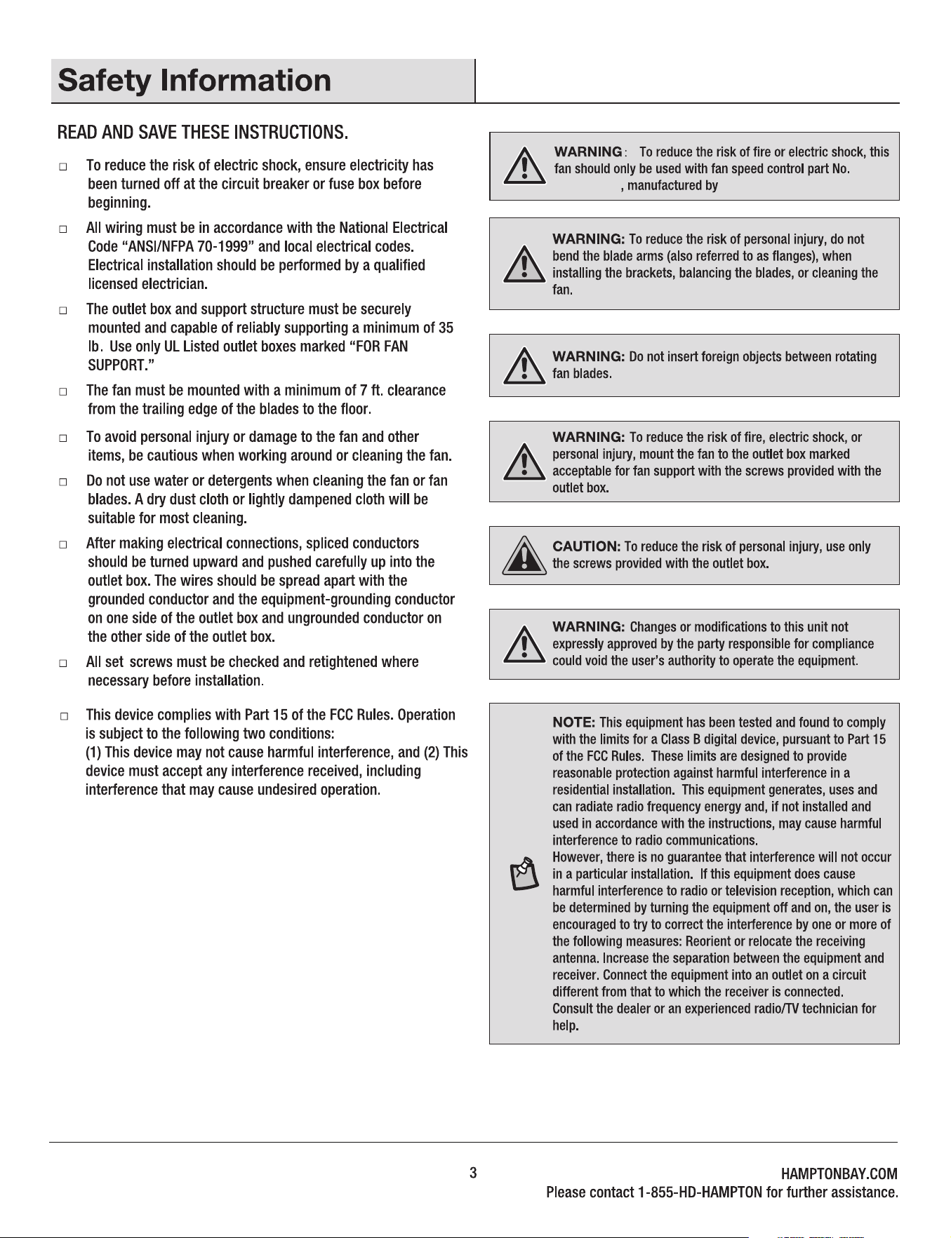
Remember to shut the power off at the
circuit breaker or fuse box.
DD (x3)
E
B
White
Black
Green
1
H
L
JJ
JJ
B
C
JJ
JJ
JJ
D
Removed one screw (JJ) from the mounting bracket (B), and loosen the other screw (JJ) around 1/4" .
C
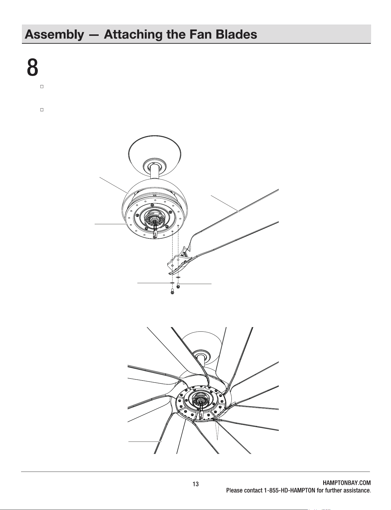
Fastening the blades to the fan motor assembly
Align the 2 holes from the blade(A) to the ywheel (I). Secure the blade with two blade washer (AA) and two metal washer (BB)
provided.
Follow the same process for the remaining seven blades (A).
BB
I
AA
BB
H
A
A
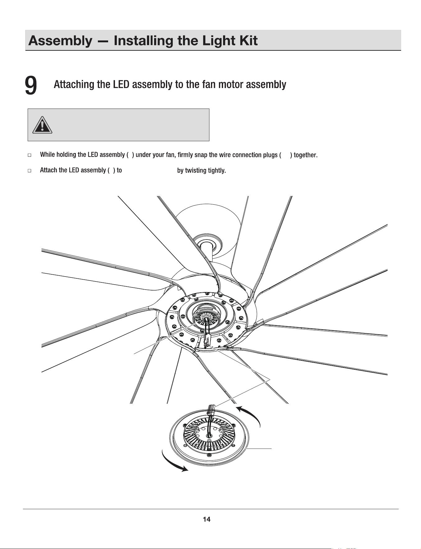
CAUTION:
To reduce the risk of electric shock,
disconnect the electrical supply circuit to the fan before
installing the light kit.
J
J
NN
NN
the switch box (00)
00
J
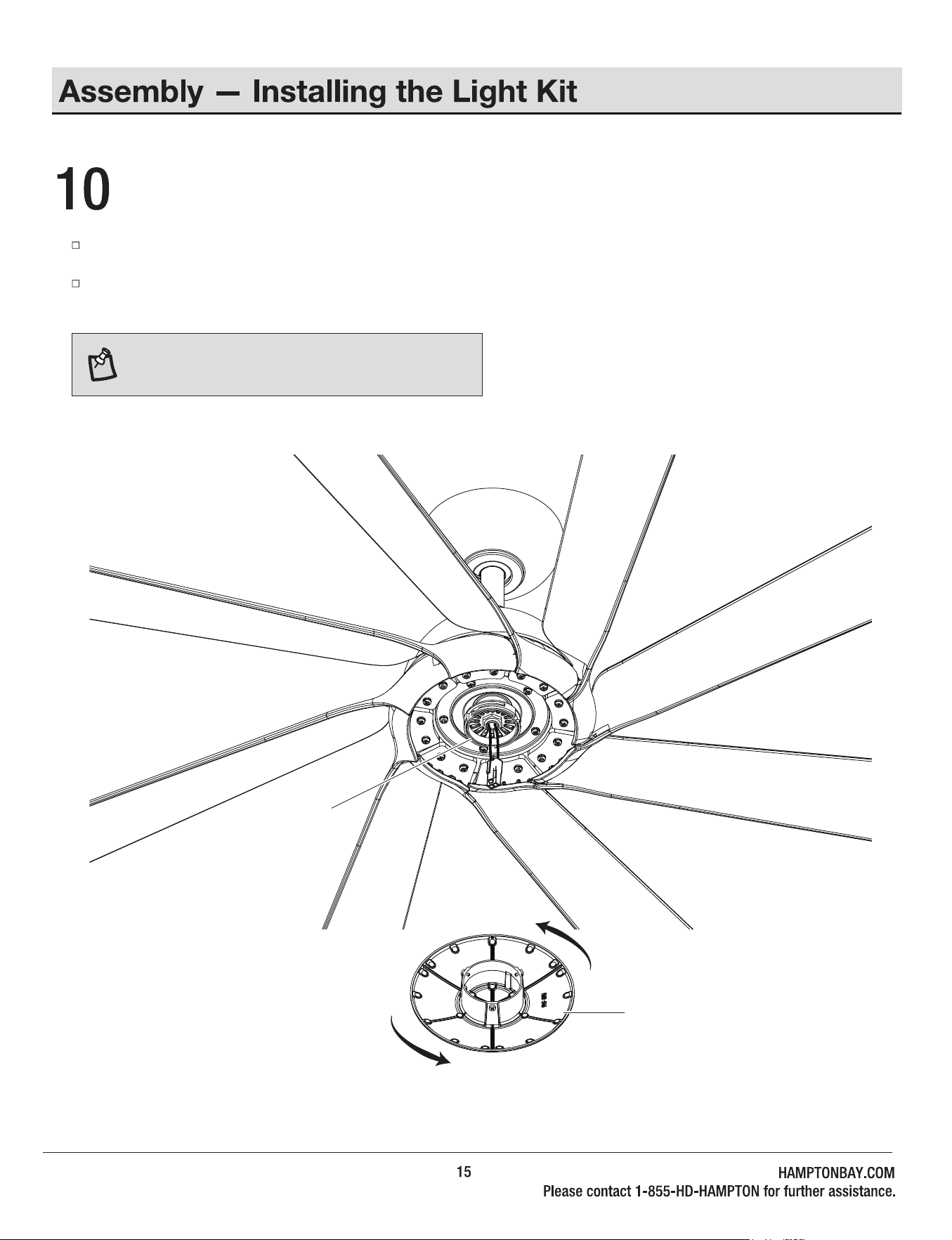
Installing the metal shade
If you want the fan to be without light, please skip the last step #9 and install the metal cap directly.
Raise the metal cap (K) up against the switch box (00) of the fan motor assembly (H) and secure it to fan by turning it clockwise
snug. DO NOT OVERTIGHTEN.
NOTE: Installing the metal shade. Make sure the metal
shade is securely tighten.
00
K
16
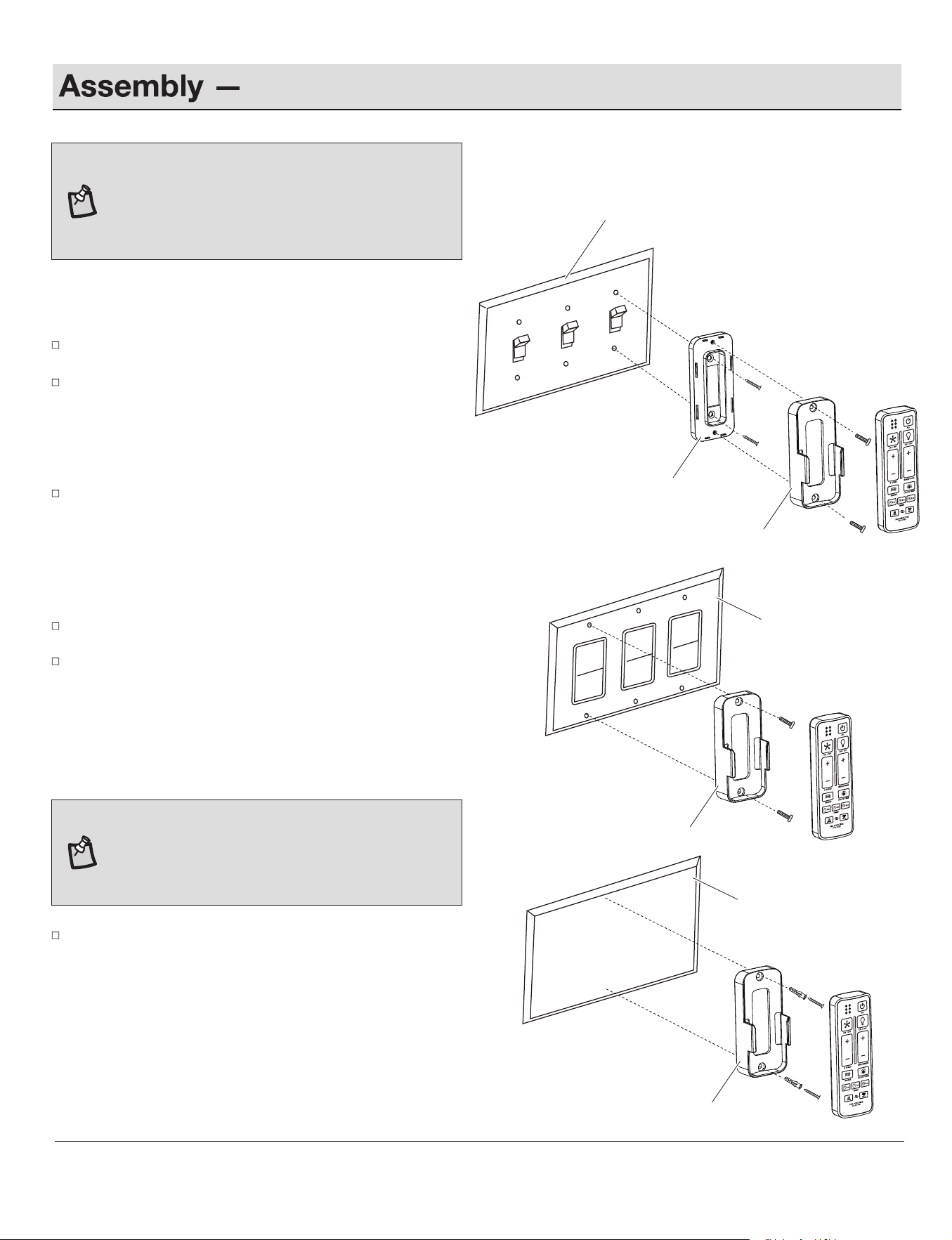
Mounting the remote wall cradle
ST3.5x13mm
A
#6/32*13mm
B
#6/32*13mm
ST3.0x18mm
C
Anchor
Toggle switch face plate
Toggle switch spacer
Paddle switch face plate
a. Attaching over a standard toggle switch
Remove the two screws from the toggle switch face plate.
Place the toggle switch spacer over the toggle switch face
plate and align the two large holes of the toggle switch spacer
with the holes in the face plate. Secure the toggle switch
spacer to the face plate using the two screws (ST3.5 x 13mm)
provided.
Attach the remote wall cradle to the toggle switch spacer using
the two screws (#6/32*13mm) provided. Screw them into the
top hole and bottom hole of the remote control holder and into
the toggle switch spacer until tight.
b. Attaching over a paddle swith
Remove the two screws from the paddle switch face plate.
Place the remote wall cradle over the paddle switch and align
the two holes of the remote wall cradle with the holes in the
face plate. Secure the remote wall cradle to the face plate
using the two screws (#6/32*13mm) provided.
c. Attaching to the wall
NOTE:
Screw wall anchors are included for extra
support. The included screws are desinged to screw
easily into the wall. If you would like a more permanent
or secure hold, install the wall anchors prior to attaching
the wall cradle to the wall.
Position the remote wall cradle in the desire position and attach to
the wall using the two anchors and the two screws (ST3.0 x 18mm)
provided.
NOTE:
The remote wall cradle is designed to allow you to
access an existing switch. The remote wall cradle can be
mounted on the wall or to the face plate of a standard
toggle switch or a paddle switch. Follow the instructions
below for the option that best suits your needs.
Remote wall cradle
Remote wall cradle
Remote wall cradle
wall
1.5V
1.5V
1.5V
Within 60 seconds of turning the fan's AC power ON, press and hold
the syncing button for 5 seconds to enter the learning function.
Once the receiver has detected the set frequency, the fan will rotate
for a while and the down light of your fan if applicable will blink twice.
The receiver has now learned the frequency which has been selected
on the transmitter. After completing the steps above, you should be able
to operate the ceiling fan and light. If the fan is not responding to the
transmitter, please turn the power off to the receiver, and repeat the
process.
Turn the power to the fan and light off. After 10 seconds, turn the
power back on to both the fan and light.
SYNCING THE RECEIVER AND THE REMOTE CONTROL
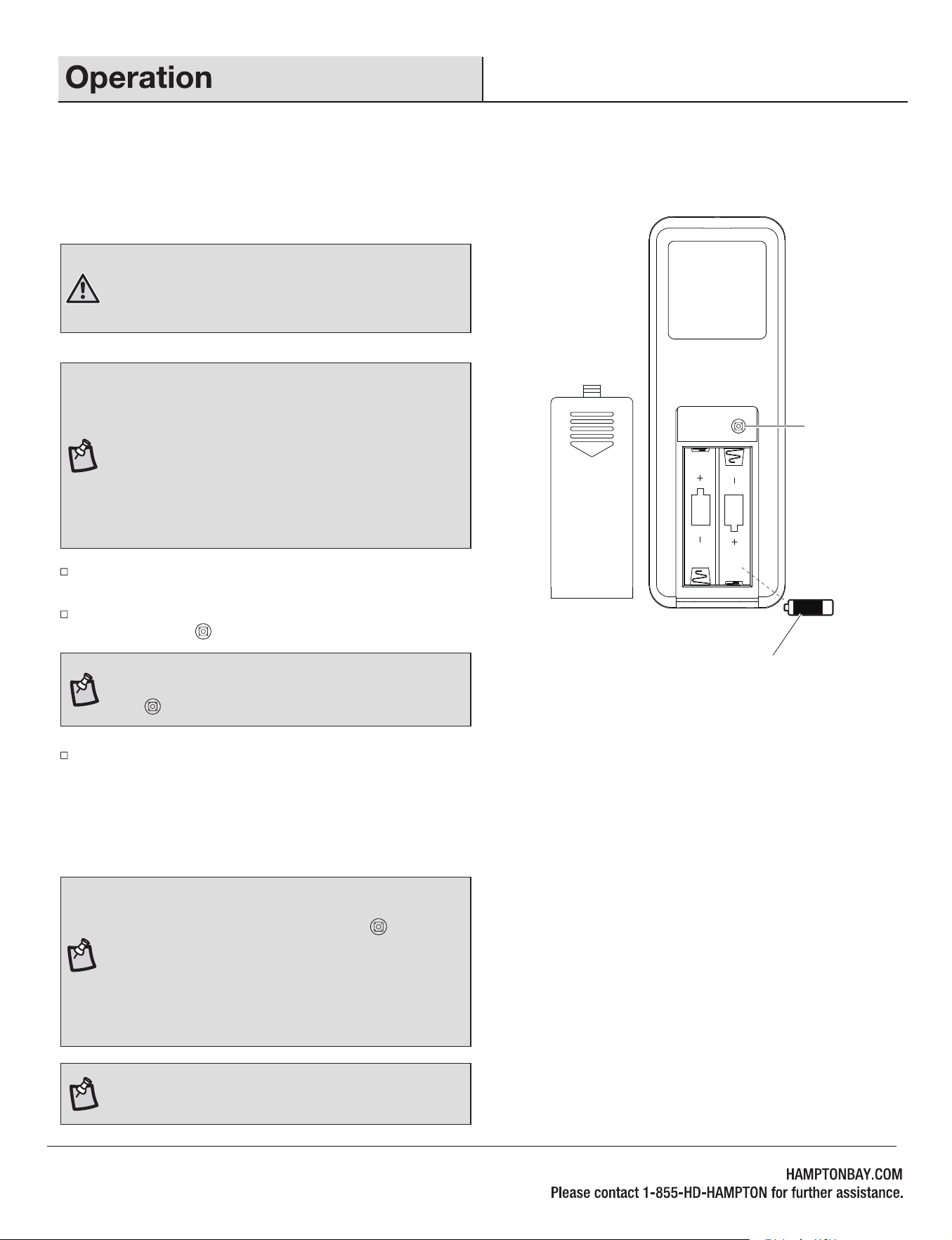
WARNING:
Do not short-circuit, disassemble, heat up,
connect improperly, or dispose of used batteries in fire. Do
not recharge or mix batteries with used or other battery
types. Immediately remove used batteries.
NOTE:
The control system isequipped with a learning
frequency function which has 64 code combinations to
prevent potential interference from other remote units. The
frequency on your receiver and transmitter units have been
preset at the factory. No frequency change is necessary. If
the fan is non-functional or if you desire to install another
fan within the same home or area with a separate
frequency code, please see this "learning process" section
of this instruction manual to re-pair the receiver and
transmitter.
NOTE:
After the AC power is on, do not press any other
button on the remote control before pressing the syncing
button . Doing so will cause the procedure to fail.
O
Syncing
button
Install two 1.5V batteries (O) into the remote control. To prevent damage
to the remote control, remove the batteries if not used for long periods
of time. Restore power to the ceiling fan and test for proper operation.
17
NOTE:
If you want to add an extra remote control to
operate the same fan, please follow the same steps as
above but instead of holding the sync button for 5
seconds, hold it for 10 seconds on the additional remote
controls you would like to pair. During this 10 seconds, the
light will blink twice and the fan will run for a moment. The
behavior will happen twice. This is an indication that the
new remote is paired, and both remotes will work with the
same fan.
NOTE:
A maximum of 3 remote controls can be paired with
one fan.
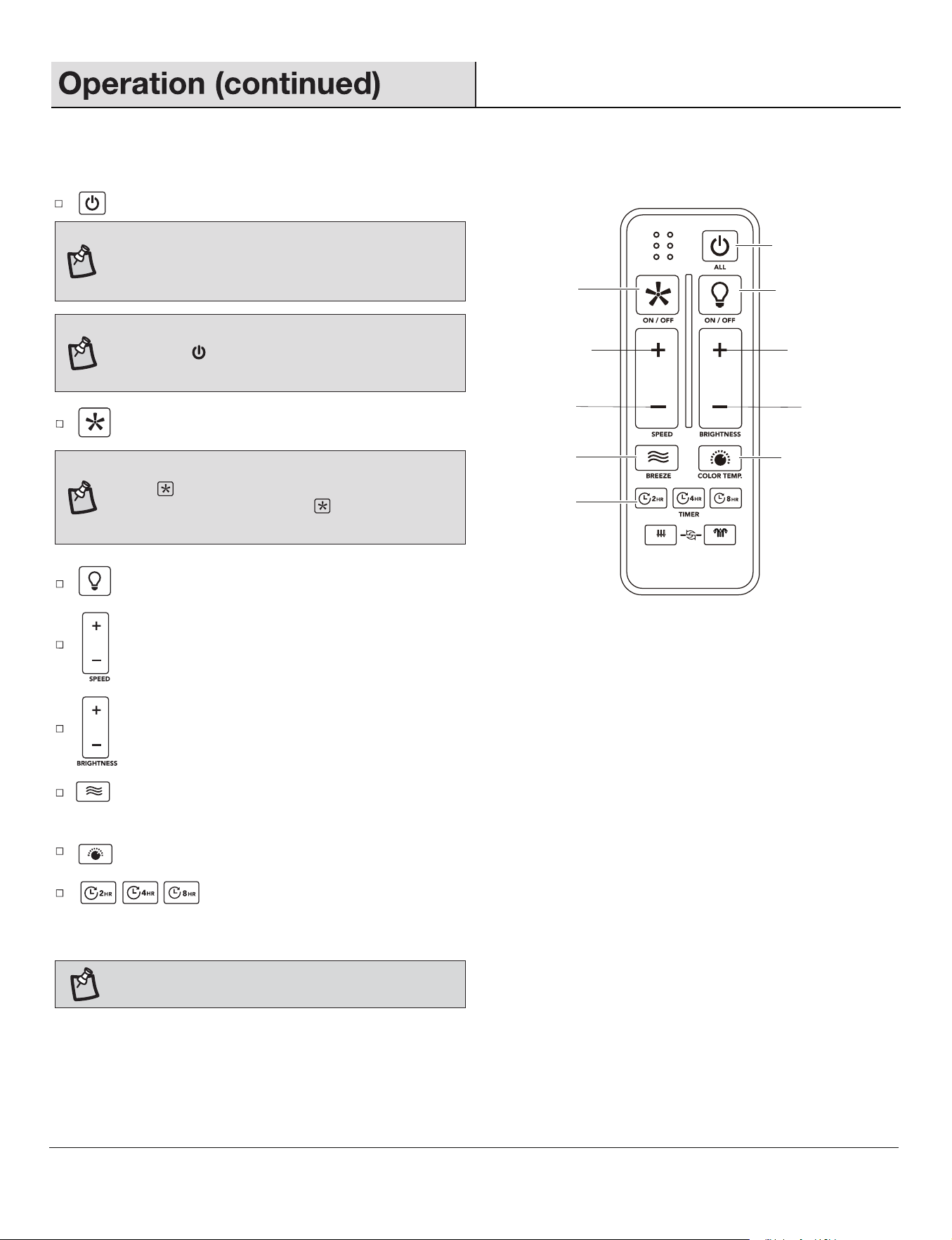
: Press and release this button to turn the fan and light on/off.
Fan & Light ALL ON/OFF
Increase the light
brightness
Decrease the light
brightness
Breeze mode
Timer
Change the light color to
3000K/4000K/5000K
Fan ON/OFF
Light ON/OFF
Increase the
fan speed
Decrease the
fan speed
: Press and release this button to dim the light.
: Press and release this button to turn the light on/off.
: Press and release the button to increase / decrease the fan speed. If fan is in Breeze mode, press and release this button to
cancel the Breeze mode and resume normal fan operation.
: Press and release this button to turn the fan on/off.
: Press and release the timer button to activate the timer function. It will automatically turn the fan off after 2, 4 or 8
hours.Press and hold this button for 3 seconds to cancel the timer. LEDs will blink 4 times, indicating cancellation of
timer.
: Press and release this button to change the light color temperature to 3000K/4000K/5000K.
NOTE:
If you are currently using breeze mode,
pressing the button will cancel breeze mode and
resume normal fan operation.
: Press and release this button to activate the Breeze mode. Press and hold this button for 3 seconds to cancel the Breeze mode.
LEDs will blink 4 times, indicating cancellation of Breeze mode.
REMOTE CONTROL OPERATING INSTRUCTIONS
NOTE:
You must turn the fan on prior to using the timer
function.
NOTE:
If Breeze mode is on, pressing the FAN ON/OFF
button will cancel Breeze mode and turn fan off.
Pressing the FAN ON/OFF button again will turn fan
on at the speed last engaged by Breeze mode.
NOTE:
The fan has memory function. It will resume
the speed and light setting on the ceiling fan prior
to the power being turned off.
18
6
SUMMER
WINTER
FAN DIRECTION
HOLD 3 SEC.
6
19
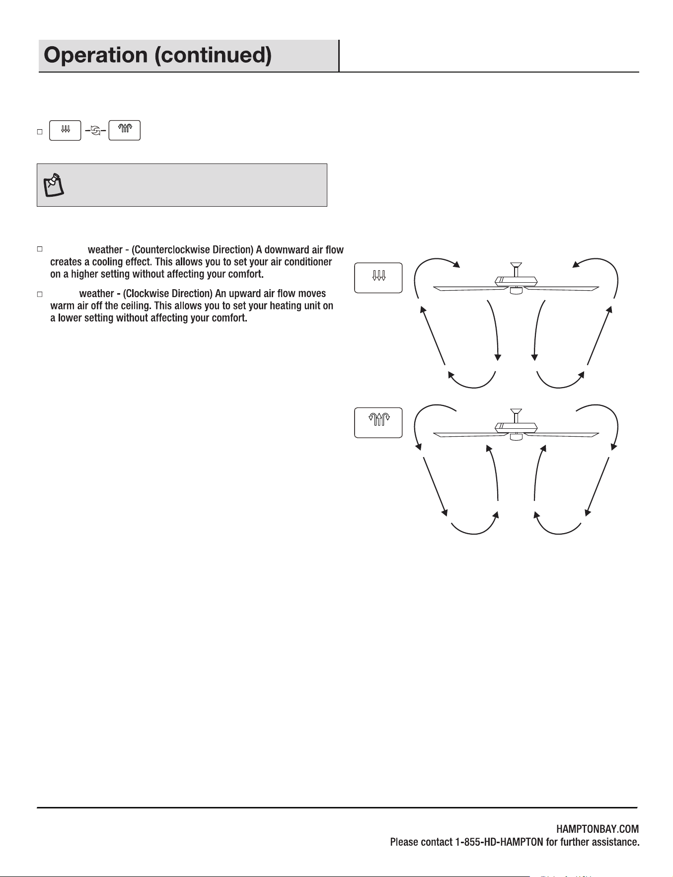
Winter
Summer
REVERSE FUNCTION
Reverse function button: Controls the fan direction.
NOTE: To change the direction of the rotation of the
blades the fan must be in operation.
SUMMER
WINTER
SUMMER
WINTER
20
21
18W
1.5V
Remote control
Remote wall cradle
22
1.5V
Remote wall cradle hardware pack (ST3.5*13mm
screw -2pcs, ST3.0*18mm screw-2pcs, #6/32*13mm
screw-2pcs, anchor -2pcs)
Coupling
6
SUMMER
WINTER
FAN DIRECTION
HOLD 3 SEC.
Metal shade
Flywheel
A
B
C
D
E
F
G
H
J
K
L
M
O
N
P
I
AA
CC
FF
DD
EE
BB
GG
HH
II
KK
LL
JJ

xxxxx
HAMPTON BAY