1
INSTALLATION, OPEATION, MAINTENANCE MANUAL
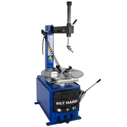
TIRE CHANGER
ITEM NO: PLA-1010BH
FOLLOW THE INSTRUCTIONS CAREFULLY TO GRANT THE MACHINE A CORRECT FUNCTION AND
LONG SERVICE LIFE.
KEEP THE MANUAL NEAR THE MACHINE ALL TIME
AND MAKE SURE ALL USERS HAVE READ THIS

2
TABLE OF CONTENT
INTRODUCTION ----------------------------------------------------------------------------------------------3
TRANSPORTATION----------------------------------------------------------------------------------4
UNPACKING------------------------------------------------------------------------------------------4
INSTALLATION---------------------------------------------------------------------------------------4
Space required---------------------------------------------------------------------------------------4
Positioning and Assembling------------------------------------------------------------------------5
Electrical connection--------------------------------------------------------------------------------5
TECHNICAL DATA------------------------------------------------------------------------------------6
OPRATION--------------------------------------------------------------------------------------------7
Trial operation----------------------------------------------------------------------------------------7
Breaking the beads----------------------------------------------------------------------------------7
Tire Demounting ------------------------------------------------------------------------------------8
Tire demounting-------------------------------------------------------------------------------------8
INFLATING--------------------------------------------------------------------------------------------9
MAINTENANCE--------------------------------------------------------------------------------------10
TROUBLE SHOOTING -------------------------------------------------------------------------------11
ELECTRIC AND PNEUM. DIAGRAMS-----------------------------------------------------12
3
INTRODUCTION
Thank you for purchase of this tire changer.
This guide has been made in order to supply the owner as well the user with the basic instructions for a correct
use of the machine
Read this guide carefully before using the machine and follow the instructions given by this guide carefully to
grant the machine a correct function, efficiency and a long service life.
INTENDED USE: This semi-automatic tire changer has been designed and manufactured specially for
mounting and demounting tires onto/from rims.
Any other use is to be considered incorrect and unreasonable. We will not hold responsibility for any
damage caused from using of this tire changer for purposes other than those specified in this manual and
therefore inappropriate, incorrect and unreasonable.
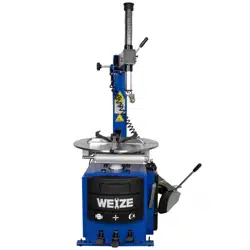
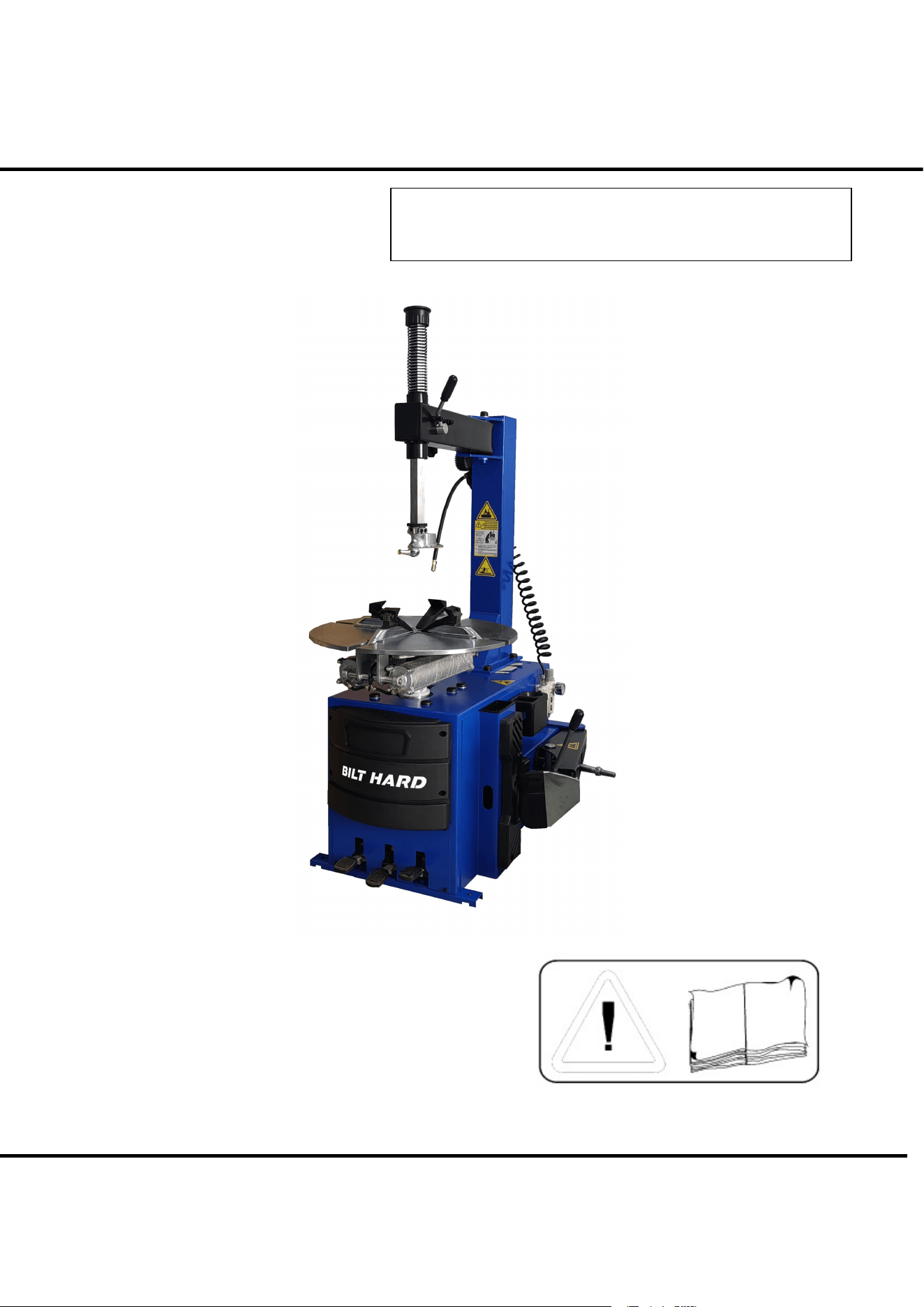
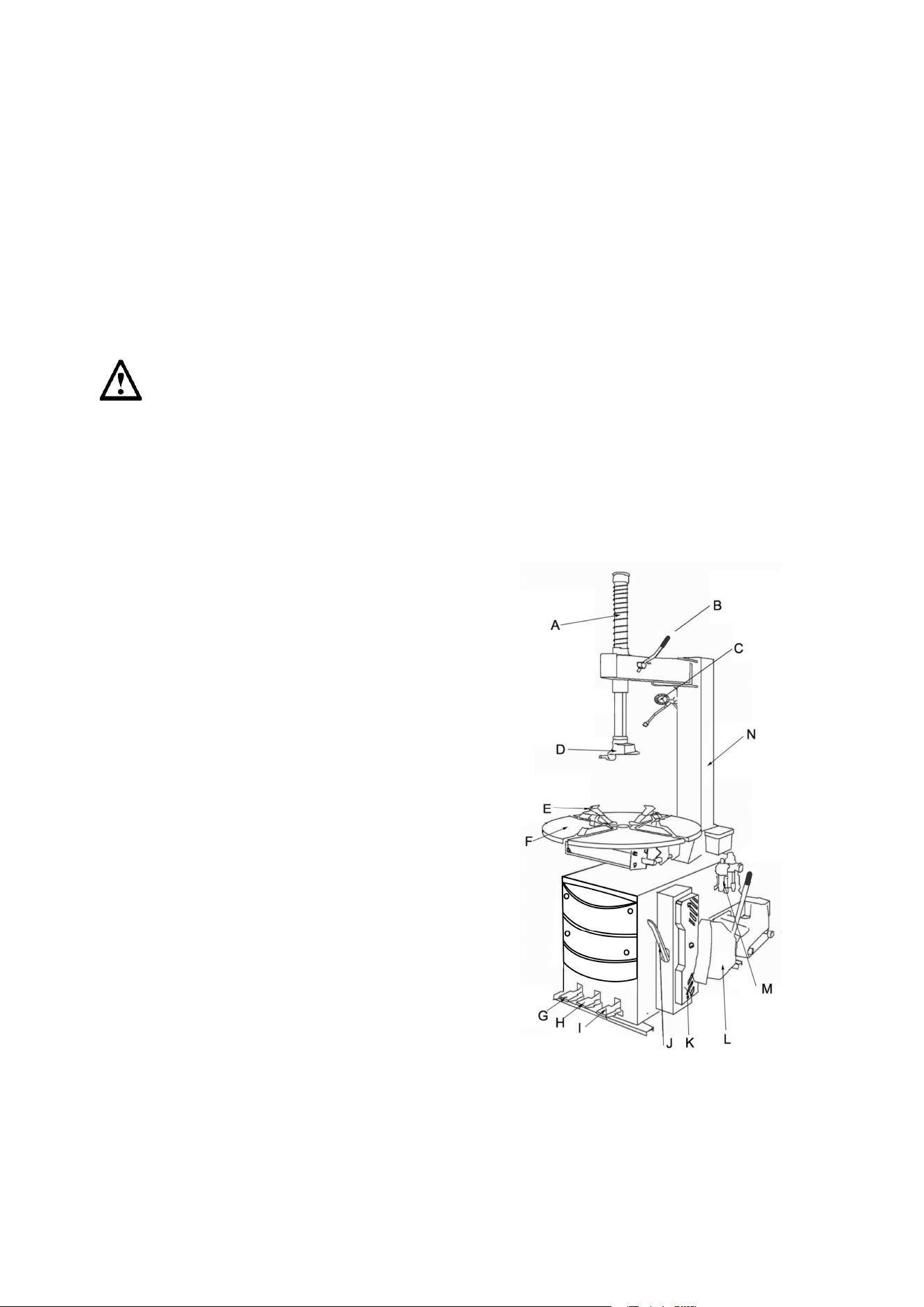
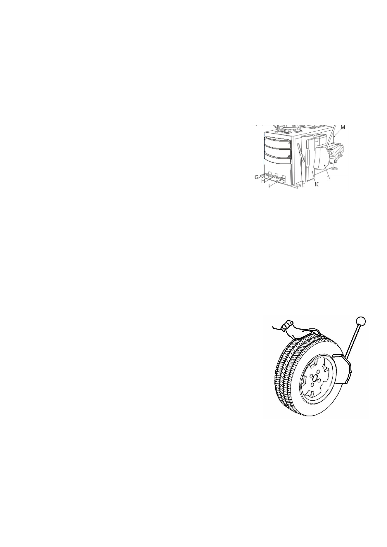
MAIN PARTS:
A: Mounting bar
B: Locking handle
C: Inflation gun
D: M/D head
E: Jaw
F: Turntable
G: Foot pedal, turntable control
H: Foot pedal, Jaw holder control
I: Foot pedal, bead breaker control
J: Crowbar
K: Wheel support
L: Bead breaker
M: Water/oil separator
N: Vertical arm
Fig 1.
4
TRANSPORTATION
The tire changer must be transported in its original packing and kept in the position shown on the package
itself.
The packed machine should be moved by means of a forklift truck of suitable capacity.
UNPACKING
Remove the protective cardboard and the plastic bag.
Please refer to Fig1 to determine if the equipment in perfect condition, making sure that no parts damaged or
missed.
If in doubt, do not use the machine and contract your retailer,
INSTALLATION
SPACE REQUIRED
The tire changer must be connected to the electric power supply and the compressed air system.
It is therefore advisable to install the machine near these power sources.
The place of installation must also provide at least the space shown below so as to allow all parts of the
machine to operate correctly and without any restriction.
Fig 2

5
POSITIONING AND ASSEMBLY
· Unscrew the pallet fixing screws and position the tire changer in the chosen place of installation.
· Unscrew the fixing screws from the arm support.
· Lift the arm and rest it on the arm support box, aligning it with the holes in which the screws were inserted.
· Retighten the fixing screws.
ELECTRICAL CONNECTION
Before making the connection, make sure the electrical system meets the requirement of the machine.
Even small jobs done to the electrical system must be carried out by professionally qualified personnel .
Steady state voltage: 0,9-1,1 of nominal voltage.
Frequency: 0.99-1.01of nominal frequency continuously; 0.98-1.02 short time.
HVF: 0.02.
Site Operating Conditions:
a. Altitude are not exceeding 1 000 m,
b. Maximum ambient air temperature is +40 C, minimum ambient air temperature is not less than 0 C,
c. Storage and transportation temperature range is -15C ~40C.
d. The relative humidity does not exceed 50% at a maximum temperature of +40 C, higher relative humidity
may be permitted at lower temperature (e.g. 90%@ 20C ).
e. The splitter can be stored or transported under ambient temperatures between –25C and +55C.
1. Connect the machine to the electric network with the protection device of under-voltage, over-voltage,
which must be provided with line fuses, a good earth plate in compliance with regulations in force and it
must be connected to an automatic circuit breaker with RCD setting set at 30 MA.
2. Connect the machine to the compressed air system by means of the air connection.(Q) that protrudes from
the rear section as shown in the diagram 12.
3. Connect the machine to the electric network, which must be provided with line fuses and of a good earth
plate in compliance with regulations in force.
4. Moreover it must be connected to an automatic circuit breaker with RCD setting at 30mA

6
TECHNICAL DATA:
External locking rim dimensions 10-20’
Internal locking rim dimensions: 12-22’’
Max. tire diameter: 970mm
Max. tire width 380mm
Bead breaker Force (10bar) 2700kg
Working pressure 8-10 bar
Power supply voltage: 110V/60HZ
Motor power: 1.5KW
Dimensions: 1025X800X975MM
Net weight: 190kg
Working noise: <70 dB
7
OPERATING
This part of the operating instructions shows basic operation and use of control. All operators should know clearly the
instruction before using the machine to prevent damaging machine and injured standby.
TRIAL OPERATION
To ensure safe operation, try to operate the machine several times without tire.
Turntable should turn clockwise when pedal G press down.
Turntable should be run anticlockwise when pedal G pulled up.
Note: If the turntable turns in opposite direction to that shown,
reverse two of the wires in the plug
.
Pedal I is used to break the beads, which will return to its original position
when pedal released
Foot pedal H is for control of the four jaws , which will close slowly when pedal is pressed again. Fig 3.
Trigger the air gun to inflate tire. .
Do not use the machine until you have read and understood the entire nearby and the warnings it provide
Before carrying out any operation, deflate the tire and take off all the wheel balancing weights.
The operation of the tire changer is divided into three parts:
a) BREAKING THE BEAD
b) TIRE DEMOUNTING
c) TIRE MOUNTING
BREAKING THE BEAD
Make sure that the tire is deflated.
Put the tire against the wheel support on the right side of the tire changer.
Position the bead breaker blade against the tire bead at distance of about
1cm from the rim
Press down the pedal to activate the bead breaker and release it when the
blade has reached the end of its travel or in any case when the bead is broken.
Rotate the tire slightly and repeat the operation around the entire circumference
of the rim and from both sides until the bead is completely separated from rim.
Fig 4

8
TIRE DEMOUNTING
Before any operation, remove the old wheel balancing weights and make sure that the tire is deflated.
Use enough grease supplied (A) (or grease of similar type) onto the tire bead.
Failure to use the grease supplied risks causing serious damage to the tire bead.
To lock the tire as follows according to the size:
Rims from 10 to18 inches
Position the clamps by pressing the pedal H down to its intermediate position;
Place the tire on the clamps and keeping the rim pressed down, press the pedal H as far as it will go.
Make sure that the rim is firmly fixed to the clamps
Lower the mounting bar until the M/D head against the edge of the rim and lock it using the lever (K). The arm is locked in a
vertical direction and the mounting head is moved to a distance of about 2mm from the rim.
Note: once the arm has been locked in a vertical direction, the mounting head must be moved away manually from the
rim(about 2mm).
With the crowbar inserted between the bead and the front section of the mounting head, move the tire bead over the mounting
head
Note: In order to avoid damaging the inner tube, if there is one, it is advisable to carry out this operation with the valve
about 10cm to the right of the mounting head.
Chains, bracelets, loose clothing or foreign objects in the vicinity of moving parts maybe cause a danger for the
operator.
While the crowbar in this position, rotate the turntable clockwise by pressing down on pedal G until the tire is completely
separated from the wheel rim.
Remove the inner tube if there is one and repeat the operation for the other bead.
TIRE MOUNTING
Before mounting the tire, check that the tire and the rim have the same diameter.
During rim mounting, NEVER keep your hands under the tire.
For a correct locking operation set the tire exactly in the middle of turntable.
When working with rims of the same size, it is not necessary always to lock and unlock the mounting bar, just move the
horizontal arm sideways with the mounting arm locked.
Lubricate the tire beads with the special grease in order to avoid damaging them
and to facilitate the mounting operations.
Inspect the tire to check its condition.
Move the tire so that the bead passes below the front section of the mounting
head had is brought up against the edge of the rear section of the mounting head itself.
Keep the tire bead pursed down into the wheel rim channel with your hands.
Press down on the pedal G to rotate the turntable clockwise. Continue until you have
covered the entire circumference of the wheel rim.
Insert the inner tube (if there is one). Fig 5.
Repeat the same operations to mount the ripper side of the tire.
9
INFLATING
The utmost attention should be paid when inflating the tires.
Keep strictly to the following instructions since the tire changer is NOT designed and built to protect the user (or anyone
else in the vicinity of the machine if the tire bursts accidentally.
-A burst tire can cause serious injury or even death of the operator.
-Check carefully that the wheel rim and the tire are of the same size.
-Check the state of wear of the tire and that is has no defects before beginning the inflation stage.
·Inflate the tire with brief jets of air, checking the pressure frequently.
·All our tire changers are automatically limited to a maximum inflating pressure of 3.5 bar (51 psi) in
any case never exceed the pressure recommended by the manufacturer.
·Keep your hands and body as far away as possible from the tire.
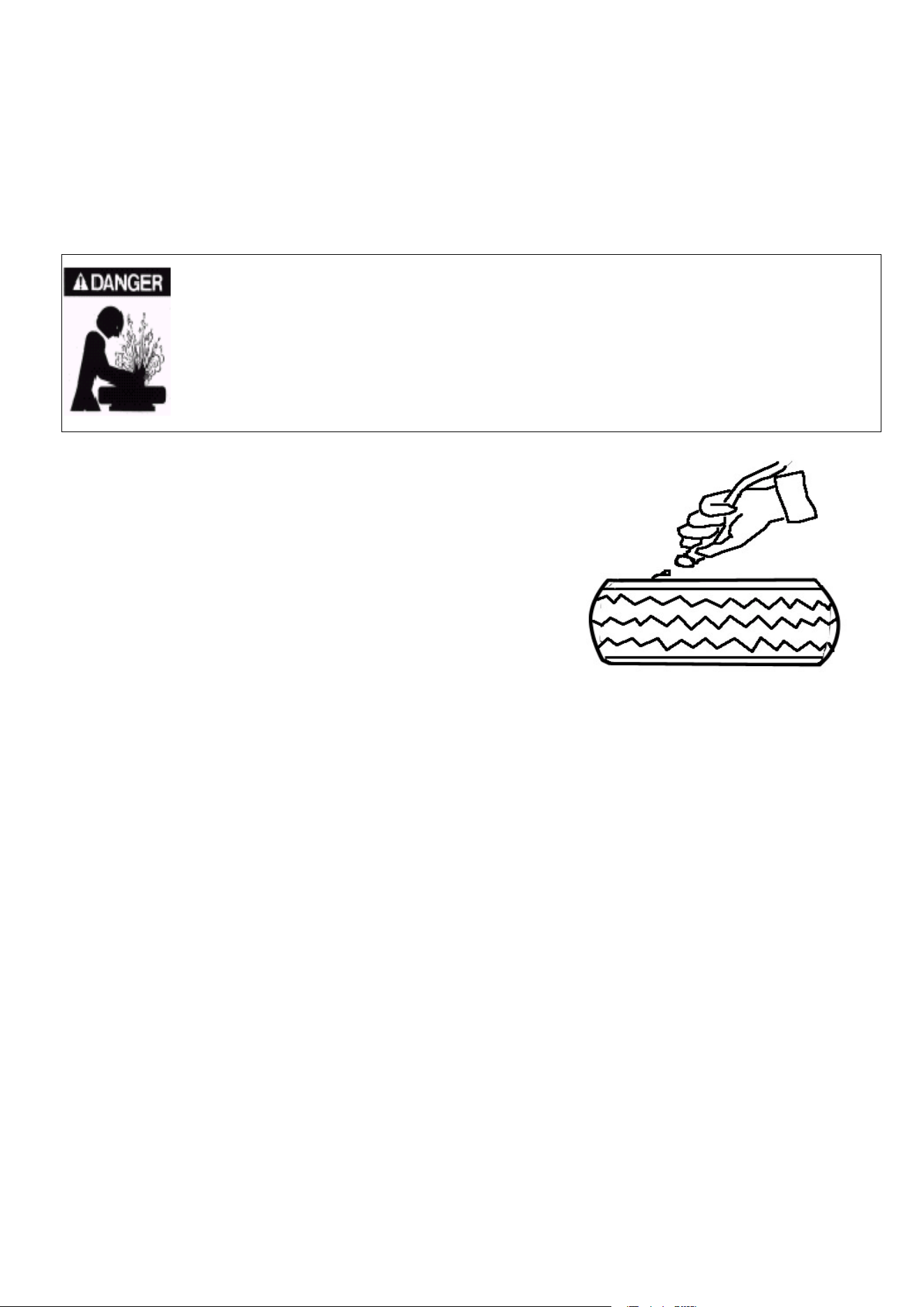
INFLATING TIRE WITH AIRELINE GAUGE
Follow below instructions to inflate a tire:
Connect the airline gauge fitting to the tire valve.
Press the airline gauge trigger so as to inflate the tire
with brief jets of air. Take care NEVER to exceed the
pressure indicated by the manufacturer.
Fig.6
10
MAINTENANCE
GENERAL WARNINGS
Untrained person is not allowed to carry out maintenance work.
Regular maintenance as described in the instructions for correct operation and long lifetime of the tire changer.
If maintenance is not carried out regularly, the operation and reliability of the machine may be compromised, thus placing the
operator and anyone else in the vicinity at risk.
Before carrying out any maintenance work, disconnect the electric and pneumatic supplies.
Moreover, it is necessary to break the bead load less 3-4 times in order to let the air in pressure go out the circuit.
Damaged parts must be replaced exclusively by expert personnel use the manufacturer’s spare parts.
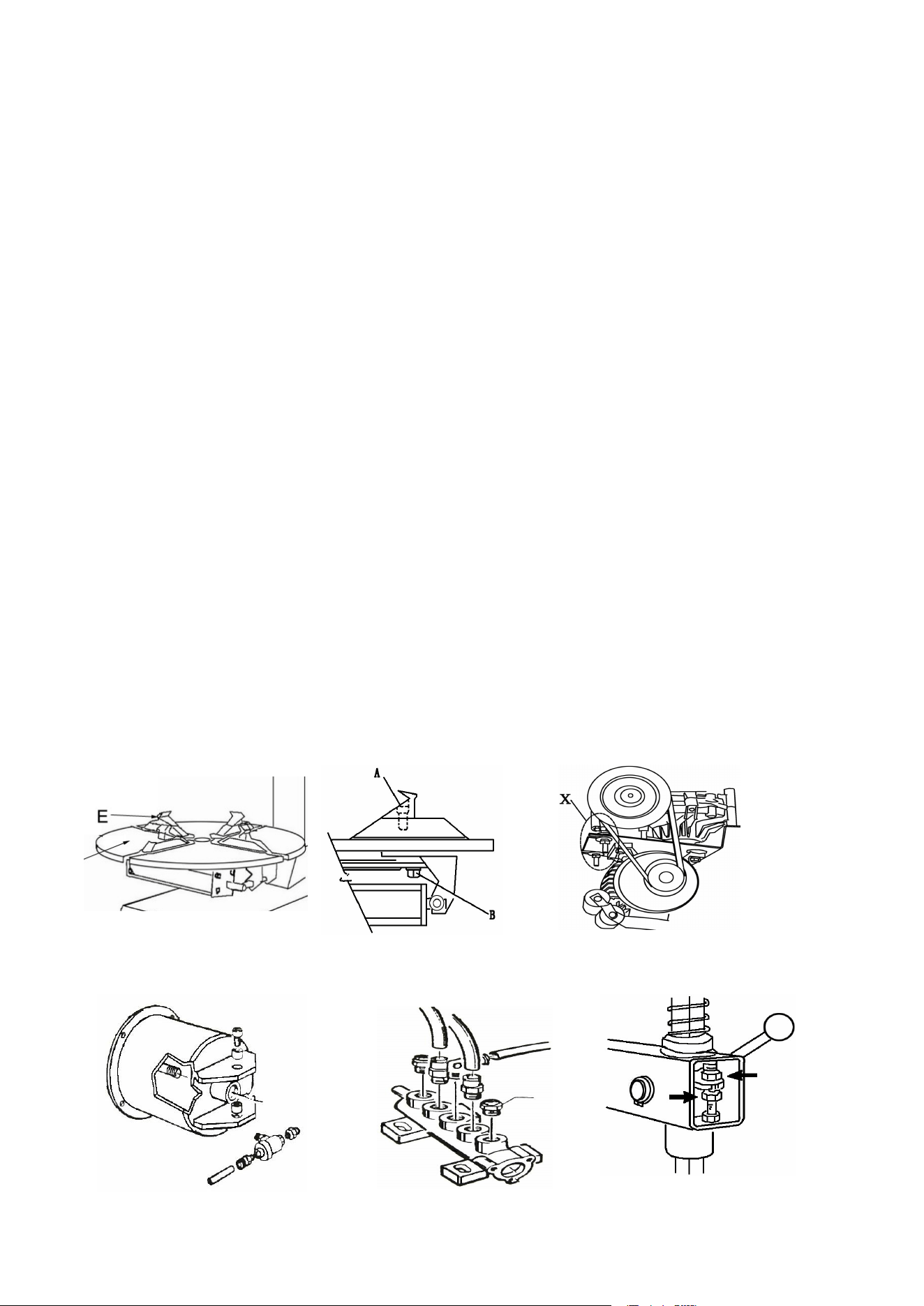
MAINTENANCE OPERATIONS
a. Clean the turntable once a week with diesel fuel so as to prevent the formation of dirt, and grease the clamp sliding guides.
(Fig 7.)
b. After the first 20days of work, retighten the clamp tightening screws and screws on the turntable slides (Fig 8.)
c. In the event of a loss of power, check that the drive belt is tight as follow:
Remove the left side body panel of the tire-changer by, unscrewing the four fixing screws.
Tighten the drive belt by means of the special adjusting screw X on the motor support (fig 9.)
e. If it is necessary to adjust the vertical arm locking plat because the tool doesn’t lock or it doesn’t rise from
the rim of 2mm necessary for working, adjust nuts as shown in figure 10.
f. For opening/closing clamps (see fig 11.) and proceed as follows:
1) Remove the left side panel of the machine body by unscrewing the four fixing screws.
2) Unscrew the silencer put on the pedal system, on the clamp opening /closing pedal
3) Clean by a jet of compressed air or, if damaged, replace by referring to the spare parts catalogue.
g. For cleaning or replacing the silencer of bead breaker , see fig.12 and proceed as shown on previous point 1 and 3.
Fig 7. Fig 8. Fig 9.
Fig 12. Fig 11 Fig 10.

11
TROUBLE SHOOTING
Turntable rotates only in one direction
Reverse broken Replace reverse
Turntable does not rotate
Belt broken Replace belt
Reverse broken Replace reverse
Check for loose wires in motor plug or the
socket replace motor
Turntable locks while removing /mounting tires
Belt loose Adjust belt tension
Clamps slow to open/close
Silencer clogged Clean or replace silencer
Turntable does not lock the wheel rim correctly
Clamps worn Replace clamps
Turntable cylinder(s)defective Replace cylinder gaskets
The tool touches the rim during the tire removing/mounting operations
Locking plate incorrectly adjusted or
defective
Adjust or replace locking plate
Turntable locking screw losses Tighten screw
Bead breaker pedal and clamp opening/closing pedal lock out of position
Return spring broken Replace spring
Bead breaking operation difficult
Silencer clogged Clean or replace silencer
Bead breaker cylinder gaskets
broaden
Replace gaskets
12
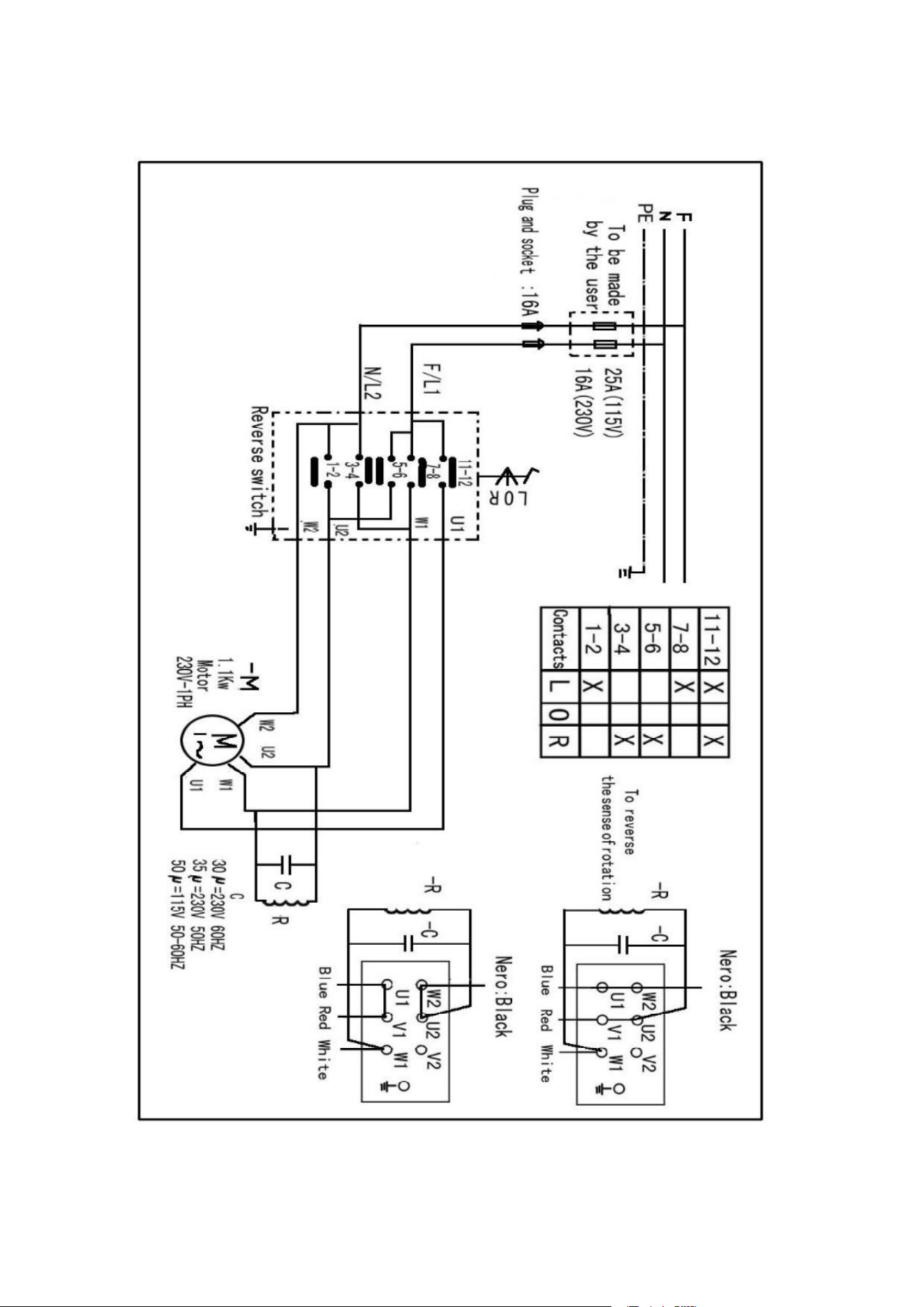
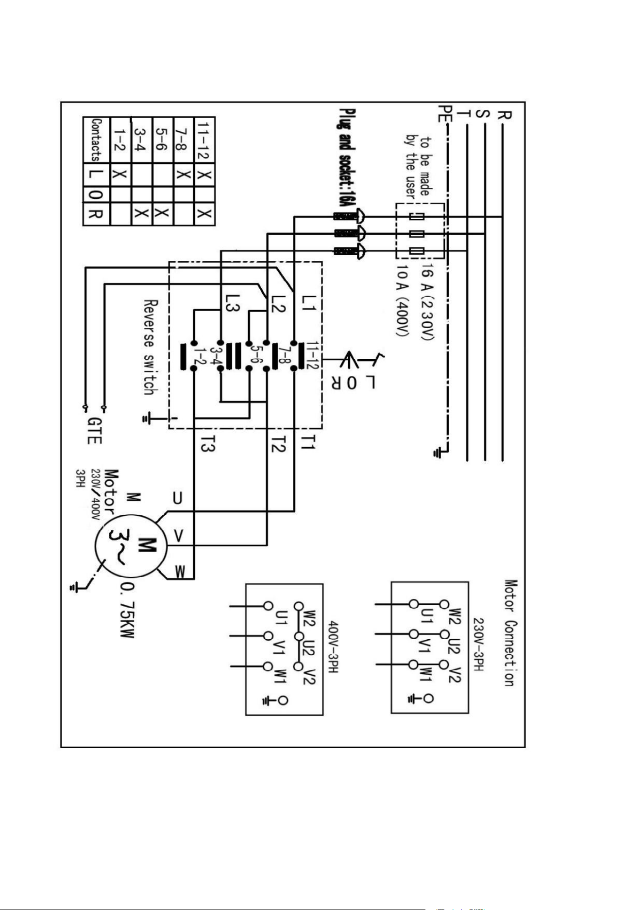
ELECTRIC AND PNEUM. DIAGRAMS
115/230V-1PH
13
230V/400V-3PH