Operator’s Manual
www.mechmaxx.com
WARRANTY
Model: TC964/TC966/TC9661/TC9662


TABLE OF CONTENTS
TABLE OF CONTENTS
SPECIFICATIONS
SAFETY SIGNS
GENERAL DESCRIPTION
1
2
DEMOUNT TIRE
12
TIRE MOUNTING
14
MAINTENANCE
17
WARNING
17
INFLATING TIRE WITH NOZZLE
15
OPERATION INSTRUCTION
6
SAFETY OPERATION RULE
6
TRANSPORT
6
OPEN PACKAGE OPERATION
6
SPACE REQUIRED
7
RECOMMENDED FOOTPRINT
7
INSTALLATION OF COMPONENTS
8
COMMISSIONING
10
DEBUGGING MACHINE
10
ADJUST THE JAW POSITION OF TURNTABLE
10
15
3
6
INSTALLATION INSTRUCTION
7
4
BREAKING THE BEAD
12
OPERATION
12
INFLATING
16
RELOCATE
16
STORAGE
16
SCRAP
17
MAINTENANCE
19
TROUBLE SHOOTING
20
CIRCUIT DIAGRAM AND PNEUMATIC SYSTEM
DIAGRAM
21STANDARD PNEUMATIC SYSTEM DIAGRAM
1
www.mechmaxx.com
TABLE OF CONTENTS
DESCRIPTION OF EQUIPMENT
Thank you for buying our semi-automatic tire changer. It is the best quality. In order to proper operation and extended the
lifetime, pls read the instruction for each operation section carefully.
PREFACE:
Provide the “complete product code” and the” model of semi-automatic tire changer”, so that we can provide you the
technical services and required parts better. At the same time, easy to operate the machine as technical parameters. If
the data in the specification is inconsistent with the label, please refer to the label.
THE DATA OF SEMI- AUTOMATIC TIRE CHANGER:
SPECIFICATIONS
2
www.mechmaxx.com
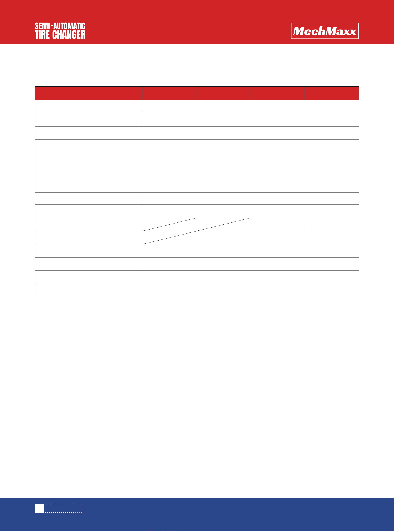
SPECIFICATIONS
Voltage
Motor Power
Inside Rim Clamp Range
Outside Rim Clamp Range
Max Wheel Diameter
Wheel Width
Working Pressure
Bead Breaking Force
Type
Help Arm
Bead Blaster
Hex Shaft Locked Type
Mount Head
Inflator
Motorcycle Rim Adapter
110v / 60hz / 1 phase
1.5 HP
12-24 in
10-22 in
117-145 psi (8-10 bar)
5510 lbs
Swing Arm
Stainless Steel & Plastic
Handheld
Sold Seperately, SKU: 200020
40 in
3-12 in
Pneumatic
Hand Held Bead Blaster
Manual
41 in
3-15 in
Left-side Assist Arm Double Assist Arms
Model TC964 TC966 TC9661 TC9662
3
www.mechmaxx.com
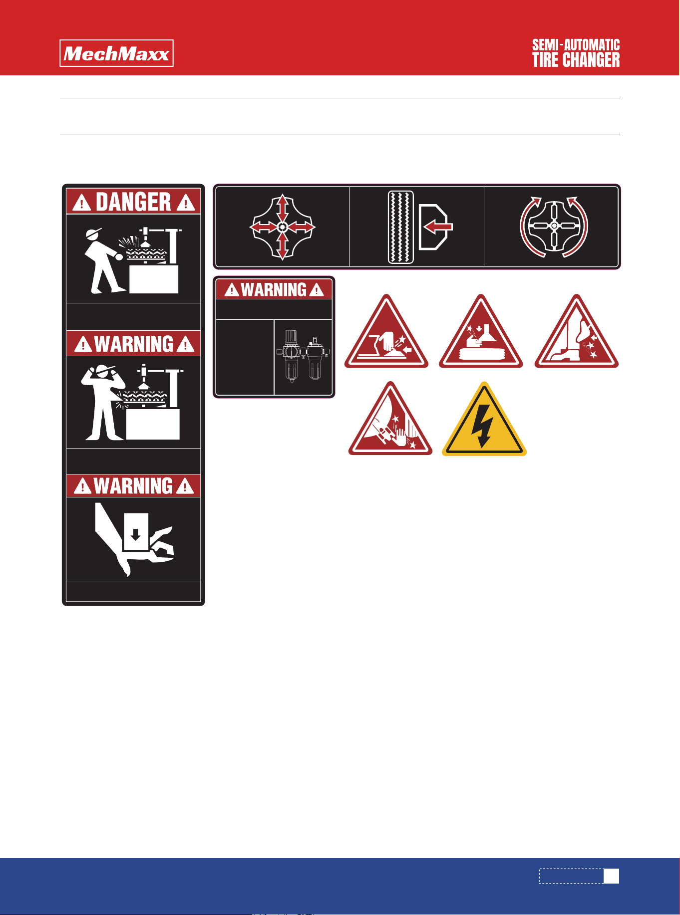
SAFETY SIGNS
SAFETY SIGNS
The rating plate on your machine may show symbols. These represent important information about the product or instruc-
tions on its use.
Please periodically check the
oil level and drain the water
Max pressure
is 1.0MPa (10
bar) Do not
exceed the
required max
air pressure
STAND CLEAR WHILE INFLATING TIRE. TIRE
OR WHEEL FAILURE UNDER PRESSURE
MAY CAUSE SERIOUS INJURY OR DEATH.
DO NOT WEAR LOOSE CLOTHING,LONG
HAIR OR JEWELRY.MOVING PARTS CAN
SNAG AND PULL
KEEP HANDS CLEAR OF ALL PINCH POINTS
M
K
N
I
P
L
Q
R
S
T
V
U
Z
Y
G
4
www.mechmaxx.com
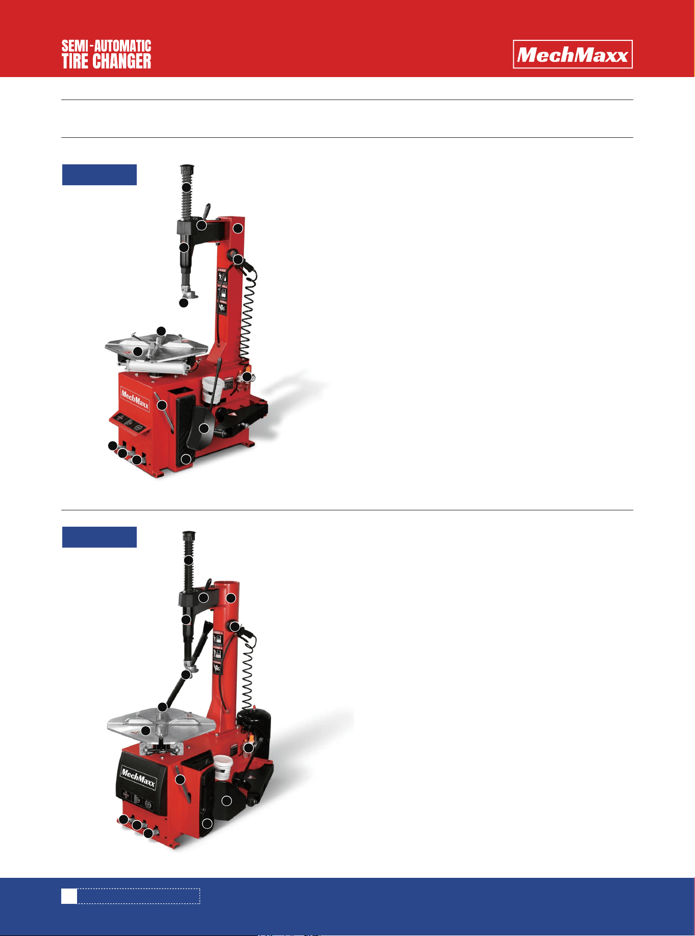
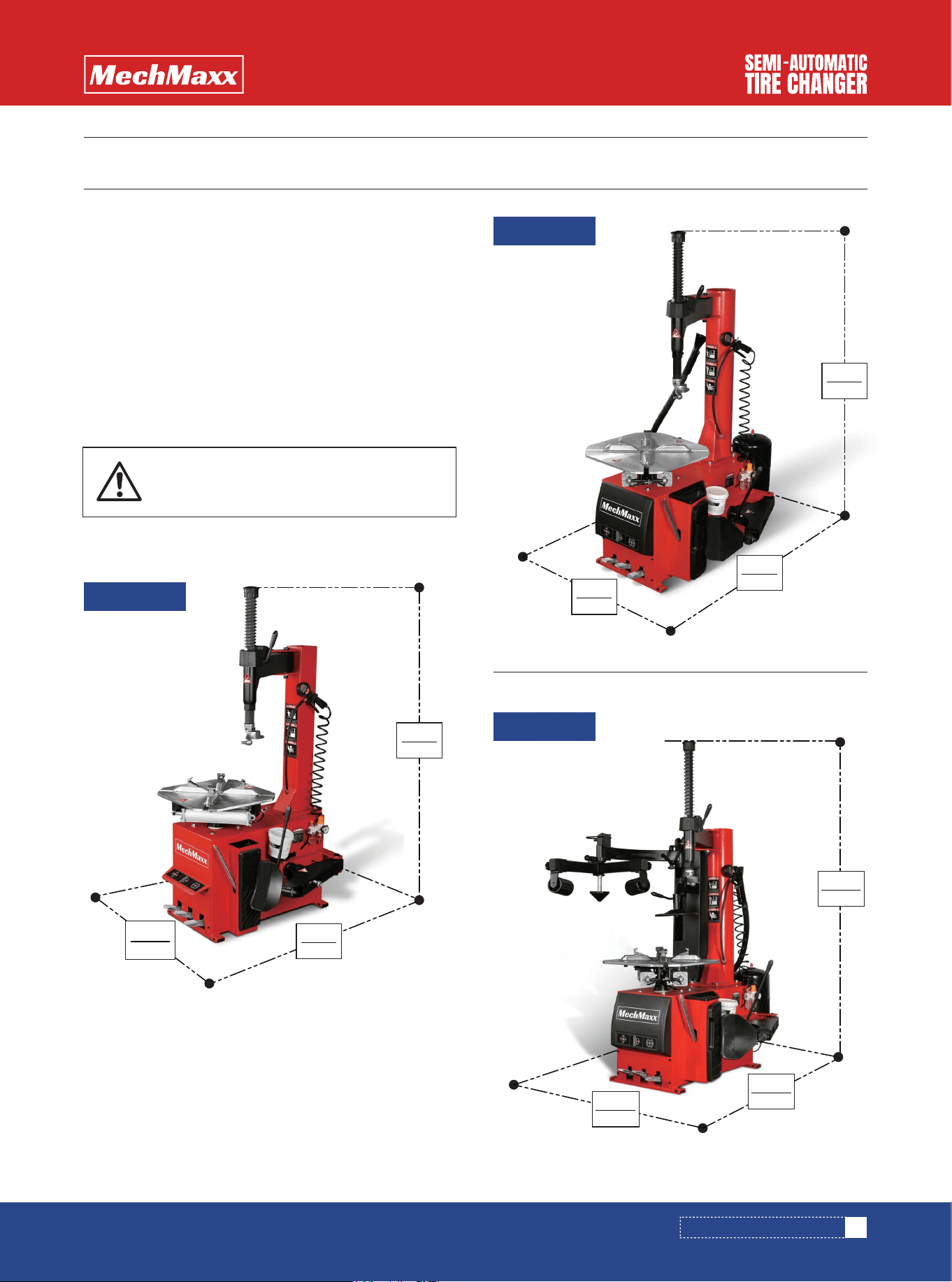
M. Hexagon Arm
K. Locking Handle
N. Horizontal Swing arm
L. Inflation Inlet
P. Column
I. Demount Head
G. Clamps
Y. Turntable
Q. Filter, Regular Lubricator
T. Leverer
R. Bead Breaker
S. Rubber Pad
V. Pedal Control Turntable
U. Pedal Control Bead Breaker
Z. Pedal Control Clamp Jaw
M
K
N
I
P
L
Q
R
S
T
V
U
Z
Y
G
M. Hexagon Arm
K. Locking Handle
N. Horizontal Swing arm
L. Inflation Inlet
P. Column
I. Demount Head
G. Clamps
Y. Turntable
Q. Filter, Regular Lubricator
T. Leverer
R. Bead Breaker
S. Rubber Pad
V. Pedal Control Turntable
U. Pedal Control Bead Breaker
Z. Pedal Control Clamp Jaw
DESCRIPTION OF EQUIPMENT
DESCRIPTION OF EQUIPMENT
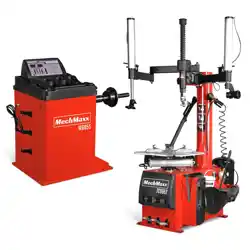
TC964
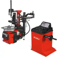
TC966
5
www.mechmaxx.com
M
K
N
I
P
L
Q
R
S
T
V
U
Z
Y
G
B
A
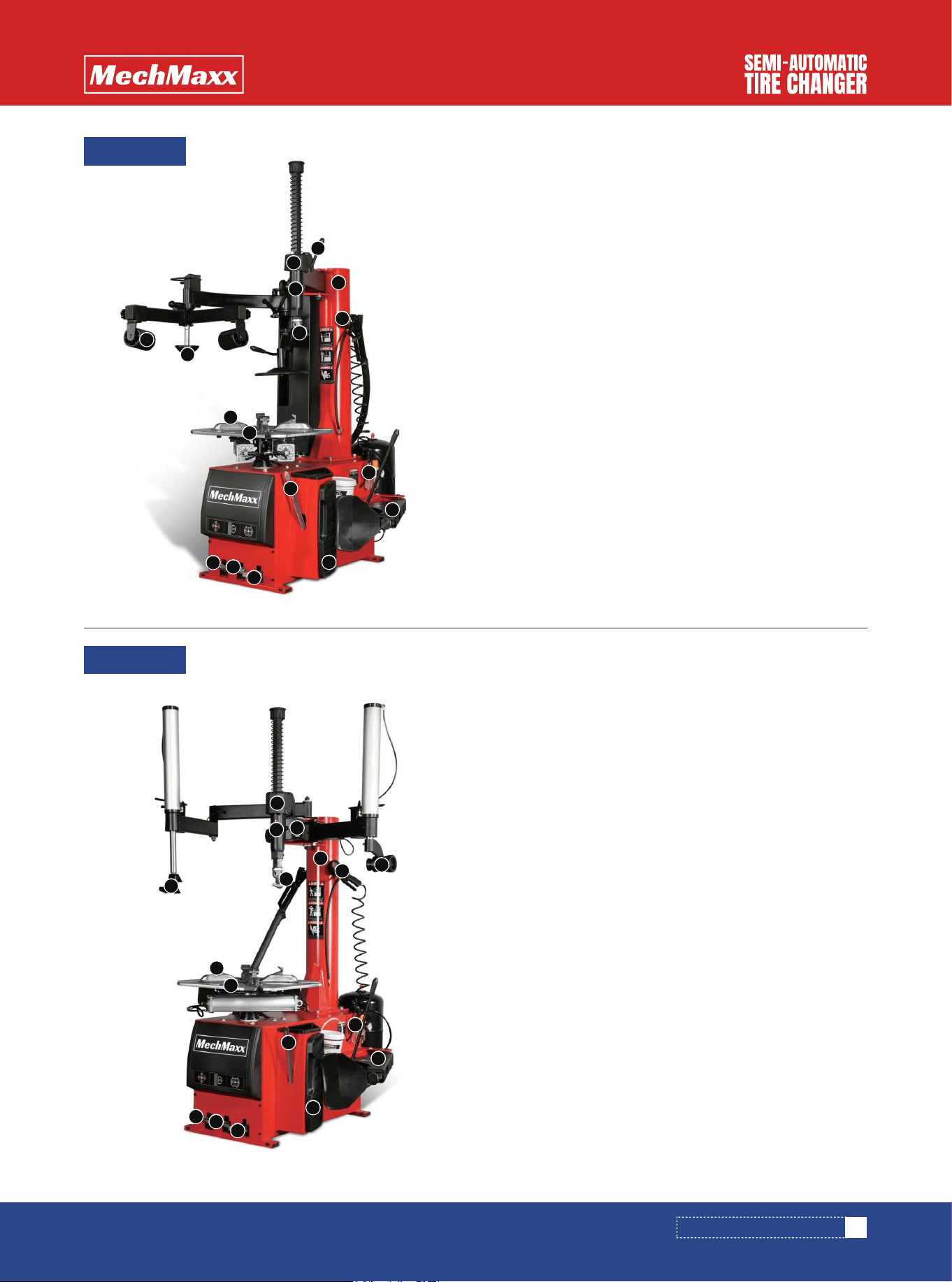
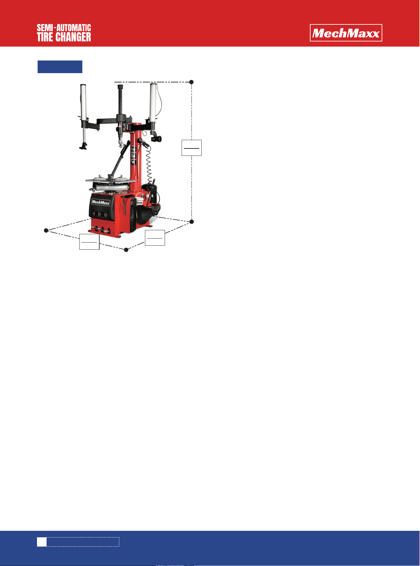
M. Hexagon Arm
K. Locking Handle
N. Horizontal Swing arm
L. Inflation Inlet
P. Column
I. Demount Head
G. Clamps
Y. Turntable
Q. Filter, Regular Lubricator
T. Leverer
R. Bead Breaker
S. Rubber Pad
V. Pedal Control Turntable
U. Pedal Control Bead Breaker
Z. Pedal Control Clamp Jaw
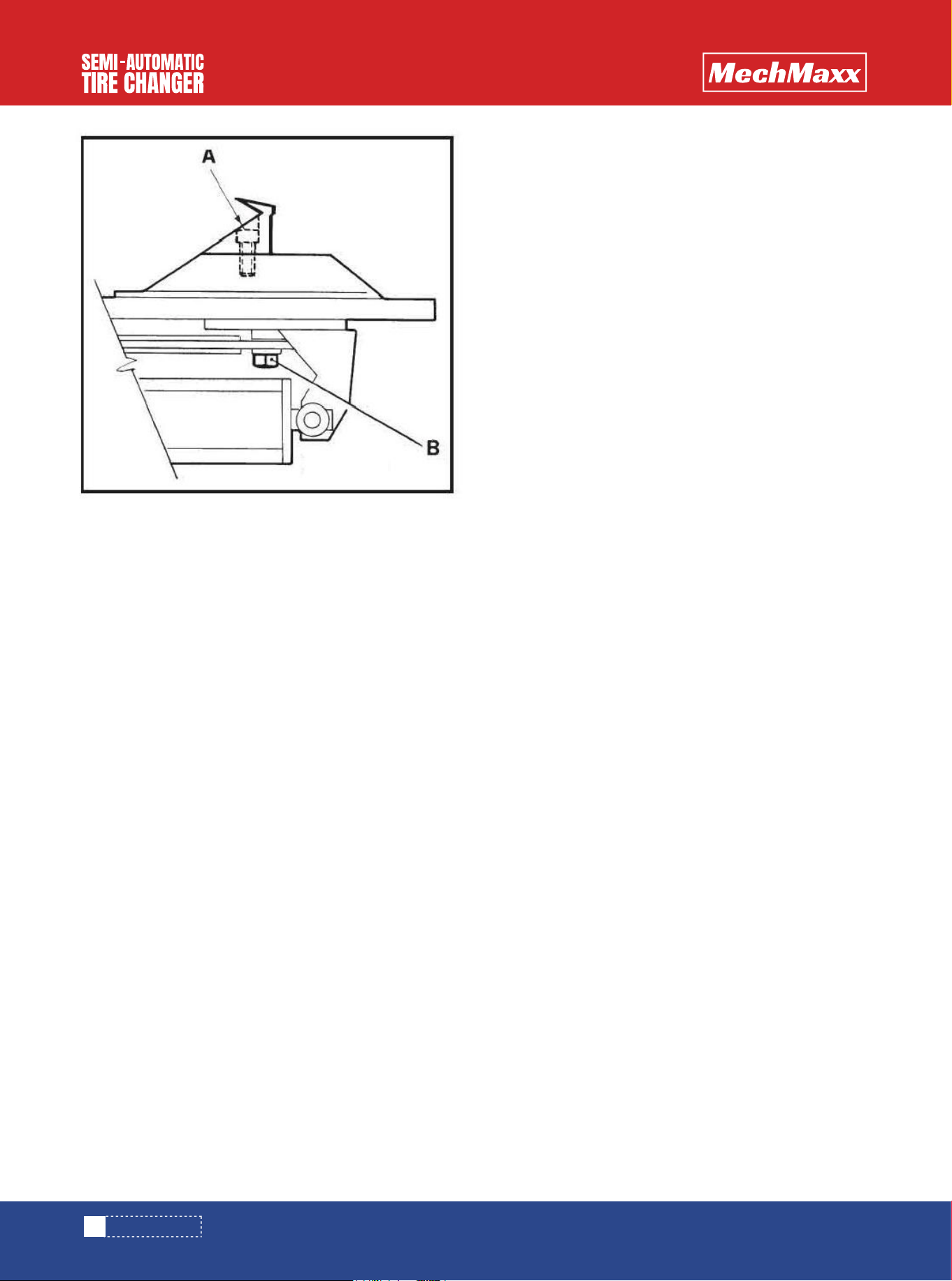
A. Press tire block
B. Press tire roller
M
K
N
I
P
L
Q
R
S
T
V
U
Z
Y
G
B
A
M. Hexagon Arm
K. Locking Handle
N. Horizontal Swing arm
L. Inflation Inlet
P. Column
I. Demount Head
G. Clamps
Y. Turntable
Q. Filter, Regular Lubricator
T. Leverer
R. Bead Breaker
S. Rubber Pad
V. Pedal Control Turntable
U. Pedal Control Bead Breaker
Z. Pedal Control Clamp Jaw
A. Press tire block
B. Press tire roller
DESCRIPTION OF EQUIPMENT
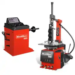
TC9661
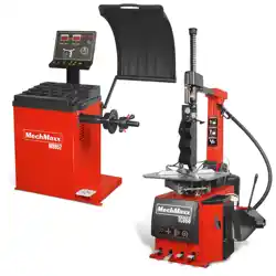
TC9662
6
www.mechmaxx.com
GENERAL DESCRIPTION
GENERAL DESCRIPTION
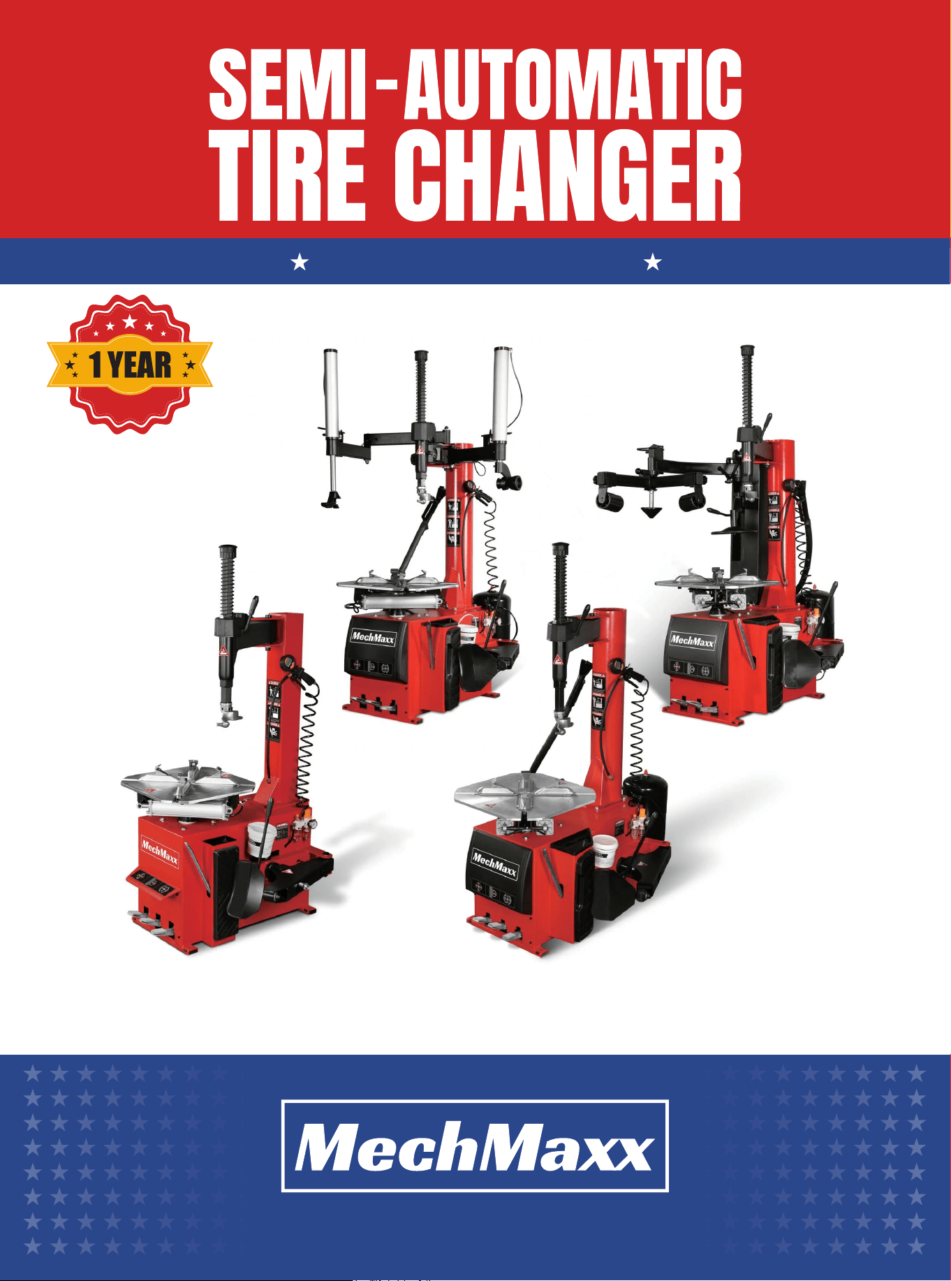
• The semi-automatic tire changer is designed to facili-
tate to mount and demount the tires which the rim
sizes is from 10"to 24" .
• Open protective boxes and plastic bags.
• Check whether the machine surface is intact and the
parts are missing and damaging.
• If any problem is found, please do not use the machine
and contact the supplier immediately.
• The manufacturer shall not be liable for any damage
caused by modification of the machine without the
manufacturer's approval.
• Manufacturers will immediately discontinue their safety
commitments if the user breaches safety rules and
causes damage of the machine's safety devices.
• If there is any damage to the safety warning sign during
the whole process, the customer can contact the
manufacturer according to the icon on page 3 to replace
the damaging icon as soon as possible.
• The semi-automatic tire changer must be transported
with the original packaging. Place as indicated on the
packing box.
• Move the packed machine by a forklift truck with corre-
sponding lifting capacity.
• The manufacturer shall not be liable for damage result-
ing from non-compliance with the instructions.
OPERATION INSTRUCTION
SAFETY OPERATION RULE
TRANSPORT
OPEN PACKAGE OPERATION
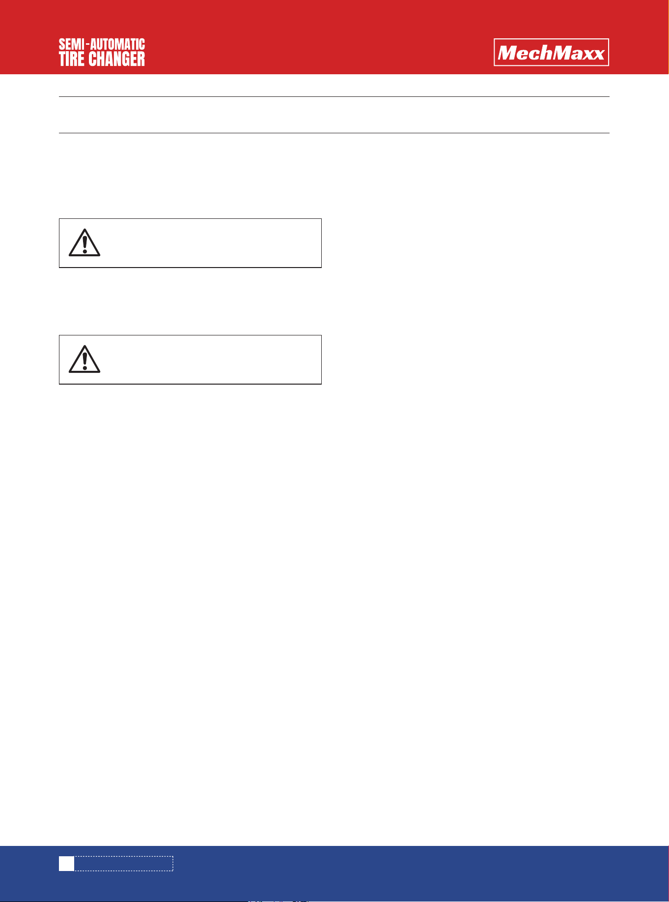
Operation against instruction is prohibit-
ed.
The semi-automatic tire changer must be
operated by trained personnel.
1780mm
70”
35.4”
900mm
43.3”
1100mm
Pic. 4
7
www.mechmaxx.com
INSTALLATION INSTRUCTION
INSTALLATION INSTRUCTION
• The installation position of the machine must meet the
standard of safe working.
• The semi-automatic tire changer should be placed near
the main power supply and compressed air system.
• The minimum space of the installation position shall
not be lower than the space that be shown in figure 4 to
ensure normal operation without any restriction.
• If the machine is installed outdoors, a protective
shelter must be built.
SPACE REQUIRED
RECOMMENDED FOOTPRINT
The semi-automatic tire changer is
prohibited to use in explosive gas
TC964
1900mm
74.8”
Pic. 4
53.1”
1350mm
43.3”
1100mm
TC966
1900mm
74.8”
Pic. 4
1350mm
53.1”
2050mm
80.7”
TC9661
8
www.mechmaxx.com
INSTALLATION INSTRUCTION
• Connect the machine to the compressed air system.
(as shown in figure 5/c)
• Step on the pedal to control the bead breaker and the
piston rod of cylinder can be extended. (as shown in
figure 5/d)
• Install the tire pressure device as shown in figure 5/e.
- Insert tire pressure device to bearing, insert the screw
hole, not to tighten with the nut or the wrench.
- The piston rod of cylinder through the rotation hole in
the pressure device.
• Screw on the nut, but don't tighten it.
- place the spring at the specified point
• Tighten the screws on the tire pressure device as
shown in figure 5/f.
• Tighten the nut on the piston rod of the cylinder as
shown in figure 5/g.
• Unscrew the fixed screws on the packing wooden pallet
and place the semi-automatic tire changer on the
ground.
• As shown in figure 5/a, unscrew 6 screws from the box
body and install the vertical column at the designated
position. Tighten the screws.
Note: for semi-automatic tire changer, the following three
operations are not required:
• Remove pin shaft, nut, washer and adjusting spacer
from horizontal swing arm.
• Apply lube to the support on horizontal swing arm.
Insert adjustment spacer to prevent friction of horizon-
tal swing arm.
• Place the horizontal swing arm on the vertical column,
insert the pin shaft and tighten it with the nut and
washer.
Note: before connecting all power, check that the instal-
lation status of the machine is consistent with the instal-
lation requirements of the machine.
INSTALLATION OF COMPONENTS
Pic. 4
1350mm
53.1”
1100mm
43.3”
1950mm
76.8”
TC9662
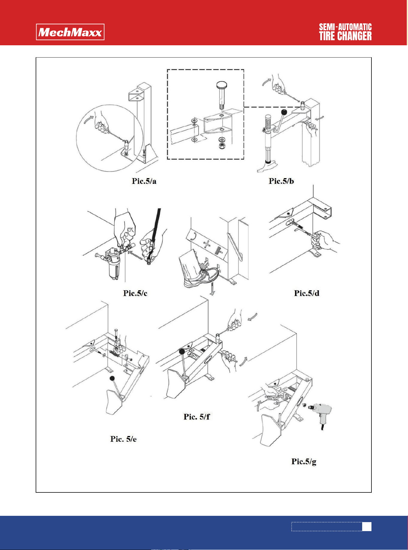
Pic.5
9
www.mechmaxx.com
INSTALLATION INSTRUCTION
Pic.6
• The compressed air system is connected to the
machine by a pipe joint (Q) on the oil-water separator
beside of the box.
• When connecting the circuit of the machine, the circuit
must be equipped with safety fuse, grounding wire and
must be installed with 30mA automatic circuit breaker.
• When the pedal (V) is stepped on, the turntable (Y)
should turn clockwise.
• When the pedal is raised, the turntable should turn
counterclockwise.
• When the pedal (U) is stepped on, the pressure tire
device (R) will start; When the pedal is released, the
tire pressure device returns to its original position.
• When the pedal (Z) is stepped on, four clamp jaws will
open (G); step on the pedal again and the clamp jaws
are closed.
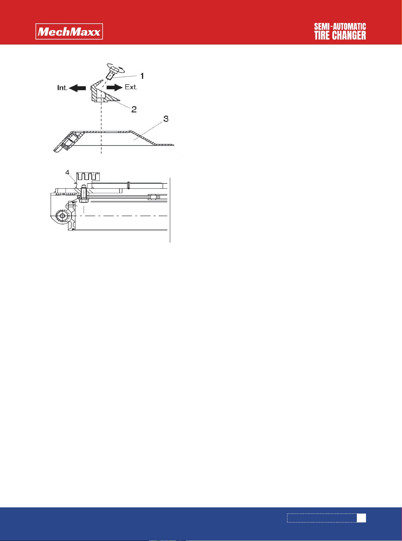
• The clamps of tire changer have been adjusted to the
central position before leave factory, the clamp rim
from outside size is from 10 "to 22". inside size is from
12 "to 24".
• If you want to demount the larger or smaller rim, you can
adjust the position of the four clamps, as shown in
figure 6/b.
The operation is as follows:
- use universal wrench unscrew the screw (1)
- mobile clamp jaw (2) and slider (3), the position corre-
sponding to one of the screw hole of the lock size
- tighten screw, universal wrench torque must be 72 N.m.
Note: the corresponding positions of the four clamps
should be ensured when the above adjustment is carried
out.
COMMISSIONING
DEBUGGING MACHINE
ADJUST THE JAW POSITION OF TURNTABLE
10
www. mechmaxx.com
Before the machine is turned on, make
sure the user's voltage and air pressure
are consistent with the machine's require-
ments.
The electrical system must be operated by
a professional.
Rim clamp from outside 10”-20”/
Rim clamp from inside 12”-22”
Rim clamp from outside 11”-21”/
Rim clamp from inside 13”-23”
Rim clamp from outside 12”-22”/
Rim clamp from inside 14”-24”
INSTALLATION INSTRUCTION
11
www. mechmaxx.com
Pic.6/b
INSTALLATION INSTRUCTION
OPERATION
The operation of semi-automatic tire changer is divided
into the following three parts:
breaking the bead /demount tire /mount tire
Mattersneedattention:
• More and more motorcycle rims are made from special
materials such as aluminum magnesium alloys and
carbon fiber, In order to lock into this kind of rim, must
use special repair tool of the motorcycle tire.
• To avoid damage, The turntable clamp jaw is fitted with
a plastic protective sleeve.
• Check the tire to see if it has emptied the gas. If not,
empty the gas
• Please close the clamp jaws of the turntable.
• Lean against the tire on the rubber pad (S) on the right
side of the automatic tire changer.
• Press the bead breaker closer to the edge of the rim
1cm (figure 8). It should be noted that the bead breaker
should be placed on the tire instead of the rim.
Apply special lubrication to the rim.
• Step on the pedal (U) and the pressure device is start-
ed. Release the pedal when the bead breaker completes
the operation or the rim is off.
• Gently rotate the tire and repeat in the rest of the tire
until the flange is completely off the rim. Repeat on the
other side of the tire.
BREAKING THE BEAD
DEMOUNT TIRE
12
www. mechmaxx.com
OPERATION
Please read the instruction manual care-
fully and note before operating the
machine.
You have to be very careful when you are
operating bead breaker. When the pedal is
operated, the breaker arm will swing
rapidly and forcefully, and any object
within the movable range of the breaker
arm is at risk of being crushed.
Discharge all air from the tire and remove
the balance lead from the tire.
Before any operation, check to see if the
tire is out of air. And ensure that the
balance lead has been removed from the
rim..
Do not place your hand on the side wall of
the tire during operation of the turntable.
The clamp may be pressed to your hand
when it is open
Pic.7
Pic.8
Clamp the rim
• Step the pedal (Z) to the central position and locate the
clamp (G) according to the reference scale of the
turntable.
• Place the tire on the clamp so that the rim is near the
lowest part of the clamp and step on the pedal (Z) to
the bottom.
• Make the clamp (G) closed completely.
• Place the tire on the clamps and step the pedal Z to
clamp the rim.
• Lower the operating arm (M) until the dismounting head
is supported on the rim edge and locked with the
locking handle (K).In the process, the operating arm is
locked in a fixed position in the vertical direction, and
the working head is moved to 2mm above the rim.
Note:Once the operating arm is locked in the vertical
direction, the working head must be manually removed
from the rim (approximately 2mm) with the manual wheel
on the left side of the horizontal swing arm.
• With the crowbar T interested between the bead and
the front section of mounting head I, move the tire bead
over the mounting head I with crowbar T(see pic.10).
Note:In order to avoid damaging the inner tube, if there
is one, it should be 10cm to the right of the mounting
head I about the above operation.
• While the crowbar in this position, rotate the turntable
Y clockwise by pressing down on pedal V until the tire is
completely separated from the wheel rim.
• Remove the inner tube if there is one. Repeat the same
operation for the other bead.
13
www. mechmaxx.com
Failure to apply lubricant may result in
wheel rim damage.
Necklaces, bracelets, loose-fitting cloth-
ing, or external items can cause personal
injury to the operator if they are close to
the rotating parts.
Make sure that the rim is firmly fixed to
the clamps.
Don’t put your hands on the wheel: if you
put your hands between rim and mounting
head, it may getting hurt when column
return to its original position.
Do not put your hand under the tire when
you lock the rim.
To properly lock the tires, place tire in the
center of the turntable.
Pic.9
Pic.10
Keep your hands and body as far away as
possible from the moving parts when
operating the machine, to avoid getting
hurt.
OPERATION
• Lubricate the tire beads with special grease in order to
avoid damaging them and to facilitate the mounting
operations.
• Insert the inner tube, if there is one. Repeat the above
operation for the other side of bead.
Note: When working with the rims of the same size, it is
not necessary always to lock and unlock the mounting
bar, just move away and return to its original position
about horizontal operating arm.
• Move the tire so that the bead passes below the front
section of the mounting head is brought up against the
edge of the rear section of the mounting head itself.
• Keep the tire bead pursed down into the wheel rim
channel with your hands. Step pedal V to rotate the
turntable clockwise. Continue until you have covered
the entire circumference of the wheel rim.
TIRE MOUNTING
14
www.mechmaxx.com
Don’t put your hands between tire and
clamps in operating clamps, avoiding
hands injury
Note:Turntable is always rotating clock-
wise during mounting and demounting
process, unless the machine is something
wrong or operating mistakenly, it may
rotate anticlockwise.
Note:To avoid explossion in inflating, it
is important to check the tire and rim.
Before mounting the tire, pay attention to
the following points:
• Don’t mount the tire if the outside of tire
is damaged.
• Check whether the rim is dented or
deformed. In particular, there will be
small cracks in the rims of alloy wheels,
which cannot be seen with naked eyes,
that will damage the durability of wheel,
so there will also be risks in inflating
process.
• Make sure that the wheel rim and tire
are of the same size. If you can’t make
sure of it, don’t mount the tire.
Don’t put your hands on the wheel: if you
put your hands between rim and mounting
head, it may getting hurt when operating
arm return to its original position.
Keep your hands and body as far as away
from the operating arm when rotating the
turntable, avoiding body injury.
Pic.11
Pic.12
OPERATION
INFLATING
Standard semi-automatic tire changer is equipped with
pressure nozzle to inflate a tire.
Follow below instructions to inflate a tire:
• Connect the nozzle fitting to the tire valve.
• Check the wheel rim and the tire are of the same size.
• Check the wheel flange and rim are with enough lubrica-
tion.
• Press the nozzle trigger, in this stage, control the inflat-
ing pressure, until the tire fits to the rim completely.
• Continue to inflate the tire and check the inflating
pressure frequently, never to exceed the pressure
indicated by the manufacturer.
INFLATING TIRE WITH NOZZLE
15
www.mechmaxx.com
You have to inflate the tire carefully,
following below instructions strictly. Pls
note there is no protection device on
designing of the tire changer for the
safety of the operator on the machine or
surrounded machine if the tire explode
suddenly..
• A burst of tire can cause serious injury
or even death of the operator.
• Check carefully that the wheel rim and
the tire are of the same size.
• Check the state of wear of the tire and
there is no defects before beginning the
inflation stage.
• Inflate the tire with brief jets of air,
checking the pressure frequently.
• keep your hands and body as far as
possible from the tire in inflation stage.
Danger of burst:
• Remove the tire from the turntable, if
you need more inflating pressure, place
the tire in special protection cage to
continue the inflation operation.
• Never to exceed the maximum inflation
pressure.
• Keep your hands and body as far as
away from the tire.
• Only professionals are allowed to use
the machine. Other people are not
allowed to use or approach the machine
during the inflation stage.
Pic.13
INFLATING

Forklifts are needed to move semi-automatic tire changer.
• Disconnect the electric power supply and compressed air system.
• Insert the crowbar on one side bottom of the tire changer, get the machine off the ground, and then insert the fork,
lifting it up.
• Place the tire changer in new position.
Note: Location of the new place must comply with national safety regulations.
If the tire changer need to be stored for some time, pls follow below instructions:
Disconnect all energy supplies and lubricate the slide of the clamps on the turntable to prevent oxidation.
RELOCATE
STORAGE
Make sure all energy supplies are disconnected when deciding to scrap the equipment.
• All nonferrous metals and nonmetals shall be disposed of as scrap in accordance with relevant laws and regulations.
• Process the oil inside the machine at the place specified by applicable law.
• Discard the remaining steel.
SCRAP
16
www.mechmaxx.com
RELOCATE
17
www.mechmaxx.com
Untrained people is not allowed to carry out maintenance
work.
• Regular maintenance as described in the instructions
for correct operation and long lifetime of the tire chang-
er.
• If maintenance is not carried out regularly, the opera-
tion and reliability of the machine may be compromised,
thus placing the operator and anyone else in the vicinity
at risk.
• Damaged parts must be replaced exclusively by expert
personnel use the manufacturer’s spare parts.
• It is forbidden by national safety regulation to disas-
semble and replace safety devices(safety valves and
regulating valves).
• Clean the turntable once a week with WD-40 so as to
prevent the formation of dirt, and grease the clamp
sliding guides.
• Perform the following maintenance work once a month
:
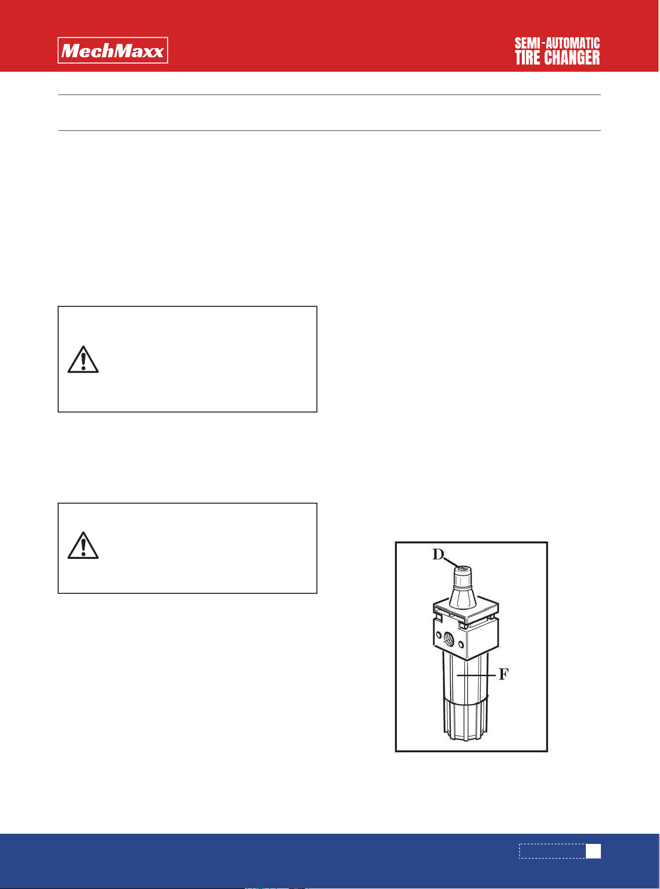
- Control the oil level of oil-water separator. If the level is
low, screw off the oil cup F before adding. Use only oils
specified by ISO HG with viscosity ISO VG32. Such as:
ESSO Febis K32,MOBIL Vacouline 1405,KLU-
BER32(Pic.15)
- Step pedal bead breaker 3-4 times, checking if some oil
filled in oil cup F. If not, adjusting screw D.(Pic.15)
Note: After the first 20 days of work, retighten the clamp
tightening screws and screws on turntable slides.(
Pic.16)
Note:In the event of a loss of power, check that the
drive belt is tight or not as follow:
Disconnect power supply before operation.
• Remove the left side body panel of tire changer,
unscrewing the four fixing screws.
• Tighten the drive belt by means of the special adjusting
screw X on the motor support.(Pic.17)
Note:If the working head is not locked or cannot be
stopped 2mm above the rim, the locking plate of the
operating arm shall be adjusted as shown.(Pic. 18).
Note:For cleaning or replacing the silencer of opening/-
closing clamps(G),proceed as follows(see Pic.19):
1)Remove the left side panel of the machine body by
unscrewing the four fixing screws.
2)Unscrew the silencer put on pedal system V, on the
clamp G opening/closing pedal.
3)Clean by a jet of compressed air, or if damaged,
replace by the same spare parts.
Note:For cleaning or replacing the silencer of bead
breaker R, see pic. 20,and proceed as shown on previous
point 1&3.
WARNING
MAINTENANCE
MAINTENANCE
Before carrying out any maintenance
work, disconnect the electric and pneu-
matic supplies.
Moreover, if it is necessary to break the
bead load less 3-4 times in order to let the
air in pressure go out the circuit.
In particular, the manufacturer shall not
be liable for any damage caused by users
using parts of other manufacturers or
damage by disassembly and damage of
safety devices..
Pic.15
MAINTENANCE
18
www.mechmaxx.com
Pic.16
Pic.17
Pic.18
Pic.19
Pic.20
MAINTENANCE

19
www.mechmaxx.com
TROUBLE SHOOTING
TROUBLE SHOOTING
Turntable rotates only in one
direction
Turntable doesn`t rotate
Turntable doesn`t work
Clamp open/close slowly
Turntable doesn`t lock the rim
correctly
The working head touch the rim
when operation
Pedal should not be located in
working position
Bead breaker
operation difficult
Universal switch
1.Replace the belt
2.Replace the universal switch
3.Replace motor
Troubleshooting
Problem
Cause
Universal switch is damaged
Belt loose
1.Locking place position is incorrect
or damaged
2.Turntable locking screw loose
Return spring damage
1.Clamp is damaged
2.Cylinder of turntable is damaged
1.Silencer trouble
2.Cylinder sealing ring of bead
breaker is damaged
1.Clean or replace the silencer
2.Replace the sealing ring
Adjust belt tension
1.Silencer trouble Clean or replace
1.Adjust or replace locking plate
2.Tighten screw
Replace the return spring
1.Replace clamp
2.Replace the sealing ring of cylinder
1.Belt is damage
2.Universal switch is damage
3.Motor trouble
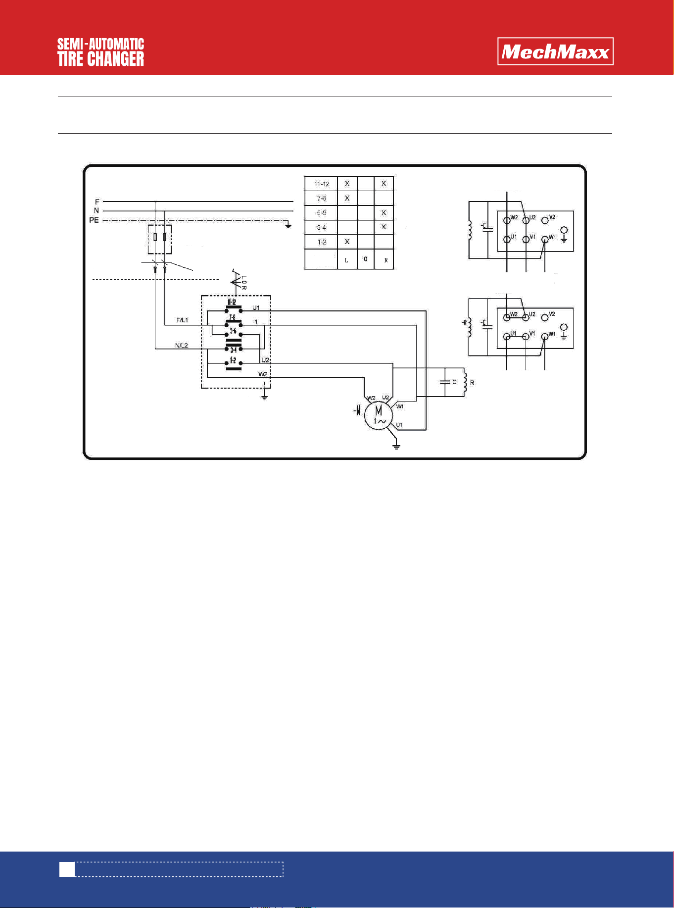
CIRCUIT DIAGRAM AND PNEUMATIC SYSTEM DIAGRAM
20
www.mechmaxx.com
CIRCUIT DIAGRAM AND PNEUMATIC SYSTEM DIAGRAM
STANDARD PNEUMATIC SYSTEM DIAGRAM
21
www.mechmaxx.com
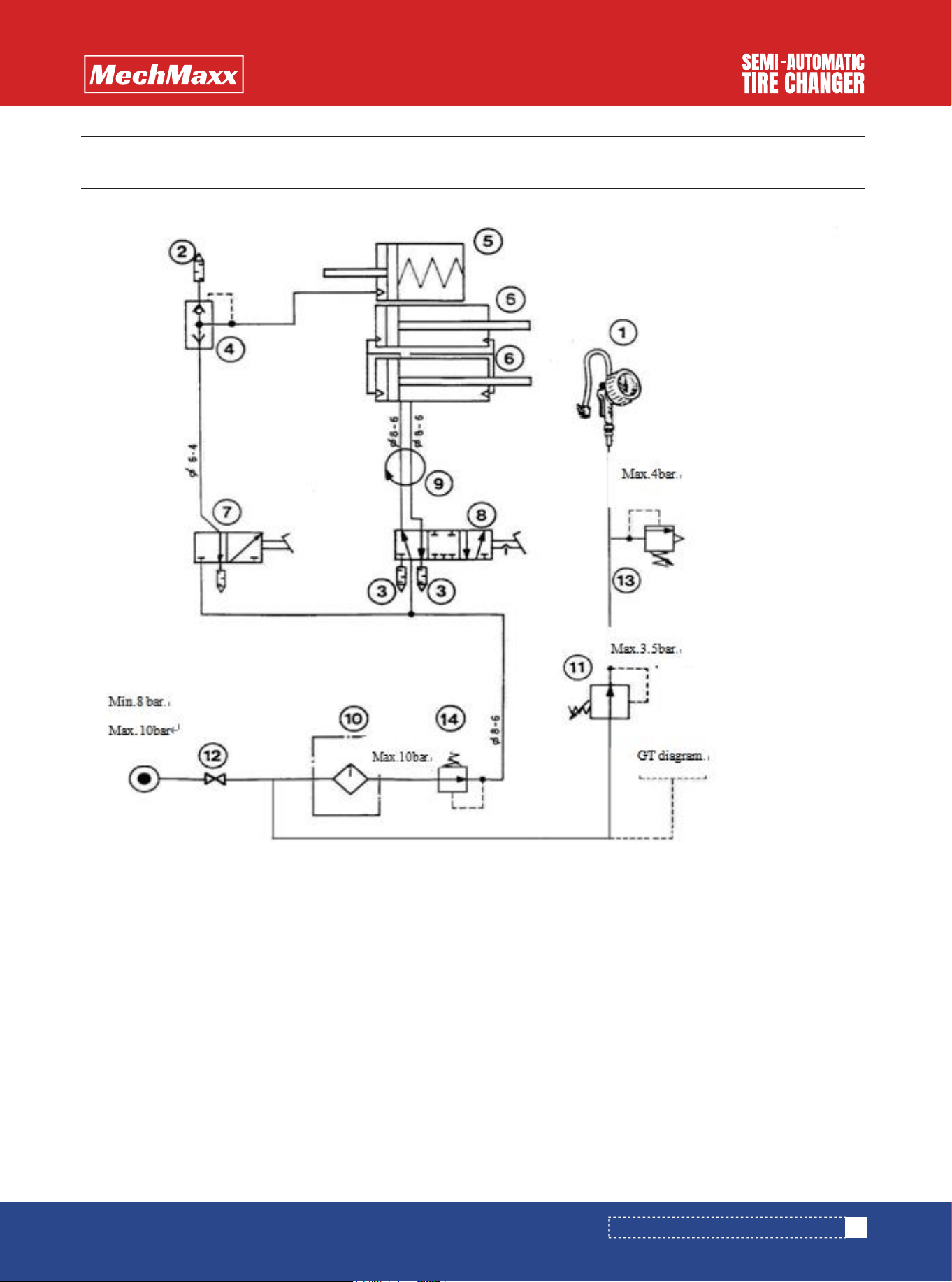
STANDARD PNEUMATIC SYSTEM DIAGRAM
1. air inflation gun 8. control valve of turntable
2.1/4” silencer 9. air guide
3. 1/8” silencer 10.oil-water seperator
4. quickexhaustvalve 11. pressureregulatingvalve
5. cylinder of bead breaker 12.ball valve
6. cylinder of turntable 13. safetyvalve
7. Control valve of bead breaker 14. pressureregulatingvalve