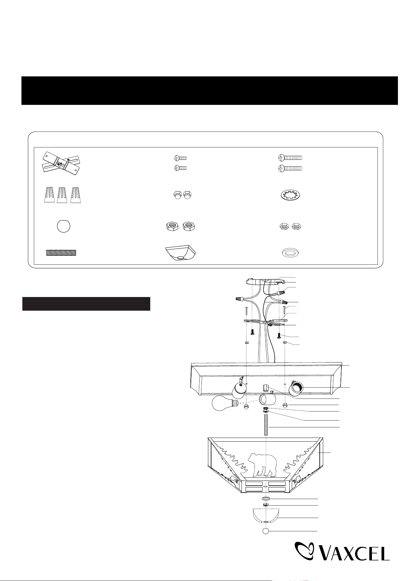
1. Thread two screws (B) through the crossbar (A),
then secure them with two lock nuts (I). Adjust
the length of the screws if necessary.
2. Attach the crossbar (A) to the outlet box with two
mounting screws (C).
3. Pull out the source wires from the outlet box.
Make wire connections using wire connectors (D)
as follows:
• Connect the hot wire (usually black insulation)
from the fixture to the black wire from the power
source.
• Connect the neutral wire (usually white insulation)
from the fixture to the white wire from the power
source.
• Attach the fixture grounding wire (usually green
with the insulation or bare wire) to the crossbar (A)
with green ground screw, then depending on local
code connect it to the house ground wire with the
wire connector (D).
Carefully put all of the wires back into the outlet box.
4. Attach the ceiling pan to the crossbar (A) by inserting the two
screws (B), then secure it with the bolt nuts (E).
ASSEMBLY AND INSTALLATION
INSTRUCTIONS
NOTES: 1. Before installing, consult local electrical codes for wiring and grounding requirements.
2. Read and save these instructions.
CC55714BBZ
Hardware Package (included):
Turn off the power at fuse or circuit box.
Installation Steps
WARNING: Turn off the main power at circuit breaker before installing fixture.
AVERTISSEMENT
Outlet Box
House Ground Wire
Fixture Ground Wire
Wire Connector (D)
Screw (B)
Ceiling Pan
Socket
Coupling
Hex Nut (H)
Threaded Pipe (J)
Frame
Cap (K)
Finial (G)
Crossbar (A)
Green Ground Screw
Mounting Screw (C)
Lock Nut (I)
(not included)
Washer (F)
Bolt Nut (E)
Hex Nut (H)
Metal Pad (L)
WARNING:
TO AVOID RISK OF ELECTRICAL SHOCK, BE SURE TO SHUT OFF
POWER BEFORE INSTALLING OR SERVICING THIS FIXTURE.
Screw (B) Mounting Screw (C)
Washer (F)
Hex Nut (H)
Threaded Pipe (J) Cap (K) Metal Pad (L)
Crossbar (A)
Wire Connector (D)
Finial (G) Lock Nut (I)
Bolt Nut (E)
Max.60W Type A Bulb
230717
Page 1 / 2
5. Install 3 x 60W max. medium base bulbs (not included). See relamping label at socket area or packaging
for maximum wattage allowed.
6. Attach the threaded pipe (J) into the coupling of the ceiling pan and secure the washer (F) and hex nut (H).
7. Attach the frame to the ceiling pan and allow the threaded pipe (J) through the frame, then secure it with metal
pad (L) and hex nut (H). Tighten the cap (K) onto the threaded pipe (J) by finial (G).
Turn on the power at fuse or circuit box.
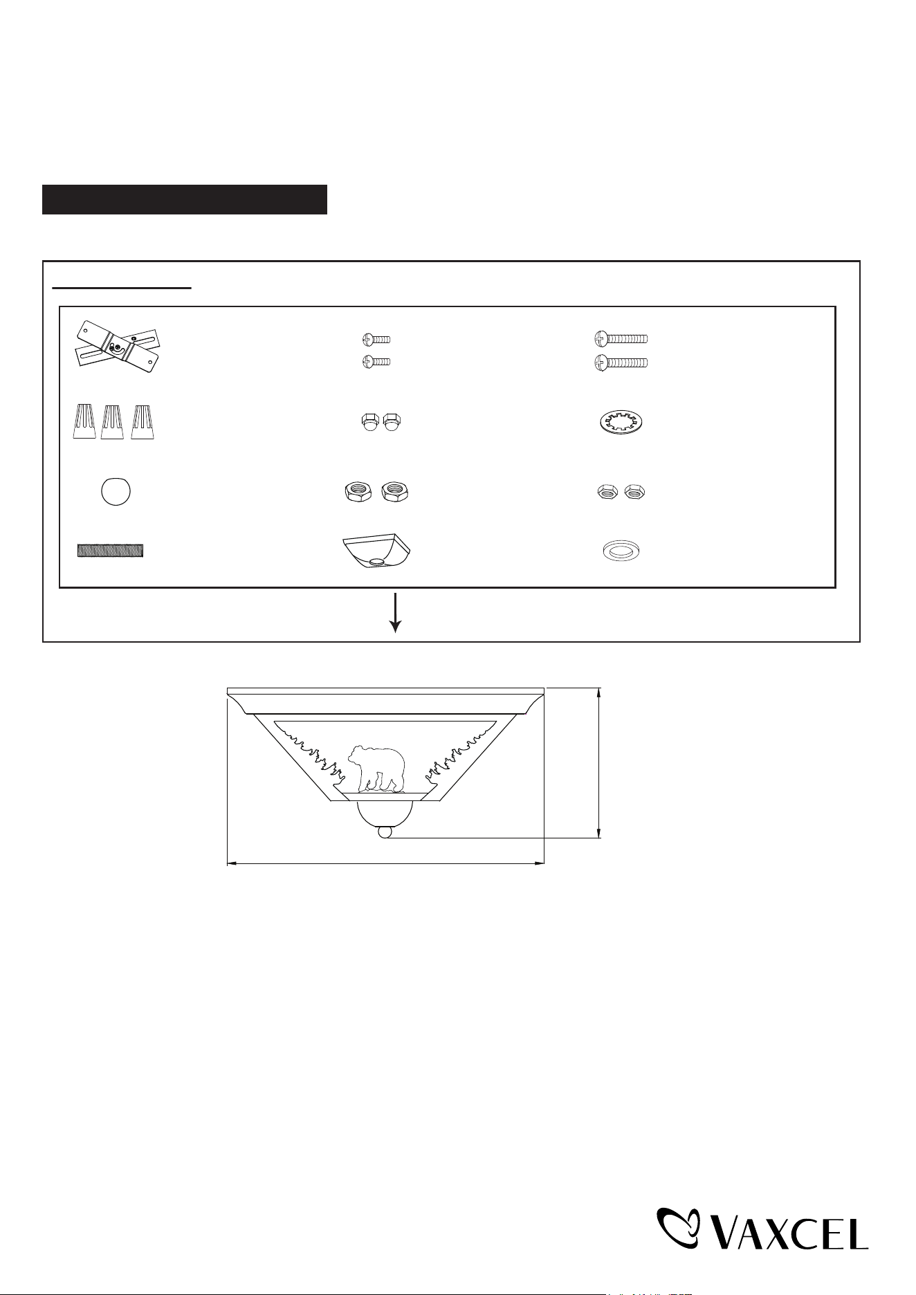
The following parts are available for reorder if damaged or missing.
Spare Parts List:
Assembly Kit
6536MM (1 SET)
Screw (B) Mounting Screw (C)
Washer (F)
Hex Nut (H)
Threaded Pipe (J) Cap (K) Metal Pad (L)
Crossbar (A)
Wire Connector (D)
Finial (G) Lock Nut (I)
Bolt Nut (E)
A: 14"
B: 7"
A
B
230717
Page 2 / 2
1 Year Warranty
How can warranty service be obtained?
1-800-482-9235
Vaxcel warrants all of our products against defects in workmanship and finishes for one year following the date of
shipment.
Exclusions: This warranty does not include the failure of products from extreme acts of nature; environmental conditions
not suited for the products intended use; operation in temperatures outside of the range specified in the instruction
manual; usage with improper power supply, power surges or dips. For coastal locations, some corrosion is considered
normal for the environment.
Vaxcel reserves the right to repair, replace or issue a credit for any properly installed product, provided it is returned per
RMA instruction. This warranty is limited to the cost of the product only and does not extend to transportation, installation
or replacement costs.