User Manual
NEUTRON
Paraphonic Analog and Semi-Modular Synthesizer with Dual 3340 VCOs,
Multi-Mode VCF, 2 ADSRs, BBD Delay and Overdrive Circuit in a Eurorack Format

2 NEUTRON User Manual
Thank you
Thank you very much for expressing your condence in Behringer by purchasing
the Neutron analog synthesizer - with 2 x 3340 VCOs, analog bucket brigade
delay (BBD), soft-clipping overdrive circuit, 5 shape morphing LFO,
12 dB multi-mode 2 pole lter, paraphonic mode, semi-modular
and Eurorack format
Table of Contents
Thank you .......................................................................2
Important Safety Instructions ...................................... 3
Legal Disclaimer ............................................................. 3
Limited warranty ............................................................ 3
About the Neutron ......................................................... 4
1. Introduction ............................................................... 5
2. Features ...................................................................... 5
3. Controls ...................................................................... 6
4. Overview .................................................................. 10
5. User Congurable Options & Features .................. 13
6. Eurorack Installation ............................................... 18
7. Software Update & Calibration .............................. 19
8. Patch Bay .................................................................. 21
9. Neutron Set-up Examples ...................................... 22
10. Preset Patches ....................................................... 24
11. Troubleshooting ....................................................24
12. Specications .........................................................25
13. Appendix A ............................................................. 27
15. Appendix B Neutron App ......................................29
16. Glossary .................................................................. 30
3 NEUTRON User Manual
Important Safety
Instructions
LEGAL DISCLAImEr
LImITED wArrANTy
Terminals marked with this symbol carry
electrical current of sucient magnitude
to constitute risk of electric shock.
Use only high-quality professional speaker cables with
¼" TS or twist-locking plugs pre-installed. Allother
installation or modication should be performed only
by qualiedpersonnel.
This symbol, wherever it appears,
alertsyou to the presence of uninsulated
dangerous voltage inside the
enclosure-voltage that may be sucient to constitute a
risk ofshock.
This symbol, wherever it appears,
alertsyou to important operating and
maintenance instructions in the
accompanying literature. Please read the manual.
Caution
To reduce the risk of electric shock, donot
remove the top cover (or the rear section).
No user serviceable parts inside. Refer servicing to
qualied personnel.
Caution
To reduce the risk of re or electric shock,
do not expose this appliance to rain and
moisture. The apparatus shall not be exposed to dripping
or splashing liquids and no objects lled with liquids,
suchas vases, shall be placed on the apparatus.
Caution
These service instructions are for use
by qualied service personnel only.
Toreduce the risk of electric shock do not perform any
servicing other than that contained in the operation
instructions. Repairs have to be performed by qualied
servicepersonnel.
1. Read these instructions.
2. Keep these instructions.
3. Heed all warnings.
4. Follow all instructions.
5. Do not use this apparatus near water.
6. Clean only with dry cloth.
7. Do not block any ventilation openings. Install in
accordance with the manufacturer’s instructions.
8. Do not install near any heat sources such as
radiators, heat registers, stoves, or other apparatus
(including ampliers) that produce heat.
9. Do not defeat the safety purpose of the polarized
or grounding-type plug. A polarized plug has two blades
with one wider than the other. A grounding-type plug
has two blades and a third grounding prong. The wide
blade or the third prong are provided for your safety. Ifthe
provided plug does not t into your outlet, consult an
electrician for replacement of the obsolete outlet.
10. Protect the power cord from being walked on or
pinched particularly at plugs, convenience receptacles,
and the point where they exit from the apparatus.
11. Use only attachments/accessories specied by
themanufacturer.
12. Use only with the
cart, stand, tripod, bracket,
or table specied by the
manufacturer, orsold with
the apparatus. When a cart
is used, use caution when
moving the cart/apparatus
combination to avoid
injury from tip-over.
13. Unplug this apparatus during lightning storms or
when unused for long periods of time.
14. Refer all servicing to qualied service personnel.
Servicing is required when the apparatus has been
damaged in any way, such as power supply cord or plug
is damaged, liquid has been spilled or objects have fallen
into the apparatus, the apparatus has been exposed
to rain or moisture, does not operate normally, or has
beendropped.
15. The apparatus shall be connected to a MAINS socket
outlet with a protective earthing connection.
16. Where the MAINS plug or an appliance coupler is
used as the disconnect device, the disconnect device shall
remain readily operable.
17. Correct disposal of this
product: This symbol indicates that
this product must not be disposed
of with household waste,
according to the WEEE Directive
(2012/19/EU) and your national
law. This product should be taken
to a collection center licensed for the recycling of waste
electrical and electronic equipment (EEE). The
mishandling of this type of waste could have a possible
negative impact on the environment and human health
due to potentially hazardous substances that are generally
associated with EEE. At the same time, your cooperation
in the correct disposal of this product will contribute to
the ecient use of natural resources. For more
information about where you can take your waste
equipment for recycling, please contact your local city
oce, or your household waste collection service.
18. Do not install in a conned space, such as a book
case or similar unit.
19. Do not place naked ame sources, such as lighted
candles, on the apparatus.
20. Please keep the environmental aspects of battery
disposal in mind. Batteries must be disposed-of at a
battery collection point.
21. Use this apparatus in tropical and/or
moderate climates.
Music Tribe accepts no liability for any loss which
may be suered by any person who relies either
wholly or in part upon any description, photograph,
or statement contained herein. Technical specications,
appearances and other information are subject to
change without notice. All trademarks are the property
of their respective owners. Midas, Klark Teknik,
Lab Gruppen, Lake, Tannoy, Turbosound, TC Electronic,
TC Helicon, Behringer, Bugera and Coolaudio are
trademarks or registered trademarks of Music Tribe
Global Brands Ltd. © Music Tribe Global Brands Ltd.
2018 All rights reserved.
For the applicable warranty terms and conditions
and additional information regarding Music Tribe’s
Limited Warranty, please see complete details online at
musictribe.com/warranty.
Zhongshan Eurotec Electronics Limited
No. 10 Wanmei Road, South China Modern Chinese
Medicine Park, Nanlang Town, 528451, Zhongshan City,
Guangdong Province, China

4 NEUTRON User Manual
About the Neutron
• Paraphonic, dual analog VCO design which allows for ingenious
music creation.
• Semi-modular design requires no patching for immediate performance.
• Dual 3340 VCOs authentically recreate the classic sound creation.
• 32 in/24 out jack patch bay for sound patching experimentation.
• 5 variable oscillator shapes with pulse width modulation for high
quality sounds.
• Blend or switch the OSC & LFO shape. A unique sound creation tool.
• Paraphonic mode allows both oscillators to be independently controlled.
• Audio-rate LFO with 5 waveform shapes, key sync, delay and MIDI sync.
• 2 assignable ADSR generators for modulation of VCF, VCA etc.
• 8192 stage Delay based on legendary BBD (Bucket Brigade Delay) technology.
• Overdrive circuit adds grit and edge to your sound.
• Complete Eurorack solution – main module can be transferred to a standard
Eurorack case.
• 36 knobs and 7 buttons give you direct and real-time access to all
important parameters.
• Powerful 12 dB multi-mode 2 pole lter with three types, Low-pass,
Band-pass and High-pass.
• Assignable Sample and Hold with Glide for added creativity.
• Slew Rate Limiter for amazing glissando sound eects.
• White noise generator dramatically expands soundscape creation.
• Pure analog signal path based on legendary VCO designs.
• External audio input for processing external sound sources.
• Servo balanced mono output for the highest signal integrity.
• 3-Year Warranty Program*.
• Designed and engineered in the U.K.
*Warranty details can be found at www.musictribe.com

5 NEUTRON User Manual
1. Introduction
An ultra-aordable leap into the warm world of analog synthesis, the Behringer
Neutron gives you the power to create virtually any monophonic sound
imaginable with incredible power and ease.
The pure analog signal path is based on the legendary V3340 VCO chip with
variable oscillator and LFO shapes which can be blended or switched for unique
sound creation. For protection and convenience, the Neutron can even be
mounted in a standard Eurorack, making it ideal for the studio and/or the road.
Owning a Neutron gives you all the power of a monster modular synthesis system
in a exible package with the ability to create bewildering, complex sounds.
1.1 Before you get started
The Neutron was carefully packed in the factory to guarantee safe transport.
Nevertheless, we recommend that you carefully examine the packaging and
its contents for any signs of physical damage, which may have occurred during
transit. If the unit is damaged, please do NOT return it to us, but notify your
dealer and the shipping company immediately, otherwise claims for damage or
replacement may not be granted.
1.1.1 Initial operation
Be sure that there is enough space around the unit for cooling purposes and, to
avoid over-heating, please do not place the Neutron on high temperature devices
such as radiators or power amps.
WARNING: The Neutron is supplied with a DC power adapter. It meets the
required safety standards. Do not use any other power adapter.
WARNING: Please make sure that all units have a proper ground connection. For
your own safety, never remove or disable the ground conductor from any units or
AC power cords in your system.
1.2 The product manual
This product manual is designed to give you both an overview of the Neutron, as
well as detailed information on each of the controls and parameters. The manual
is based on the software release, V2.0.0. The Neutron software must be updated
to at least V2.0.0 in order to use the new features and Neutron App. You will nd
an overview of the physical control elements in the next chapter.
1.3 Preparation
CAUTION: Remember to turn your monitors/loudspeakers on last when powering
up your system. Turn your monitors/loudspeakers o rst when powering down
your system.
2. Features
A Past Classic reincarnated
Great care has been taken in designing the Neutron to achieve new possibilities
in sound creation by reviving a legacy VCO chip from classic synths of yesteryear.
By creating a fresh modern take on a semi-modular synth, the Neutron gives you
the power to harness the prodigious sound of the V3340 chip. Colossal bass tones
through to screaming lead sounds can be achieved to take your sound conception
to the next level.
Paraphonic Performance
Paraphonic mode allows the two oscillators to be independently pitched when
more than one MIDI note is played. This gives tremendous tonal qualities by
hearing two pitches which can evolve and interplay with each other.
Innovative multi mode Filter
The very heart of the sound of the Neutron is its highly-exible 12 dB 2-pole
lter, which lets you freely experiment with the cuto frequency and resonance
to create out-of-this-world soundscapes. Neutron’s Filter Mode button toggles
between LFP, BPF and HPF. You can also adjust the attack, decay, release
and sustain controls to aect the cuto frequency with time. A second lter
output allows further audio contortion with its own dedicated output from the
patch bay.
Distorted reality
The VCA passes through the powerful soft clipping overdrive circuit which can
add punch and bite to your creations. This section also features a diverse tone
control to further expand your creative palette.
Oscillator and LFO morphing
The exquisite ability to blend or morph the oscillator and LFO shape lets new
adventures in tone creation begin. By modulating these waveforms, psychedelic
sounds can be cooked up comparable to other synthesizers.
Poly Chain ready
While it is largely a monophonic instrument (one note at a time) the Poly Chain
function lets you combine multiple Neutron synthesizers for polyphonic sounds.
Bucket Brigade Delay
The Neutron has an impressive analog bucket brigade delay section. Gone is
the cold digital delay chip found in most modern synthesizers and replaced
by a warm analog design. Eects from long dub delays to extreme chorusing
can be created.
Semi-modular Design
Designed around an elegantly clean, calculated work stream. The Neutron
benets greatly from its semi-modular design, which requires no patching for
quick operation. Just connect your keyboard or computer via MIDI or USB and
start exploring the versatile world of analog music synthesis.
Eurorack ready
Designed to handle the rigors of life on the road or in the studio, your Neutron
can easily be transferred into a standard Eurorack case for the perfect integration
into your existing system.
Controls and Connectivity
The Neutron has 36 knobs and 7 buttons, all laid out in a highly-intuitive format
that puts the fun back into your music creation. Input and output connections
include: Audio input, MIDI I/O and thru over USB/MIDI DIN plus a full 32 input, 24
output patch bay for countless experiments into the world of modular synthesis.
you Are Covered
We always strive to provide the best possible customer experience. Our products
are made in our own MUSIC Tribe factory using state-of-the-art automation,
enhanced production workows and quality assurance labs with the most
sophisticated test equipment available in the world. As a result, we have one of
the lowest product failure rates in the industry, and we condently back it up
with a generous Warranty program.
6 NEUTRON User Manual
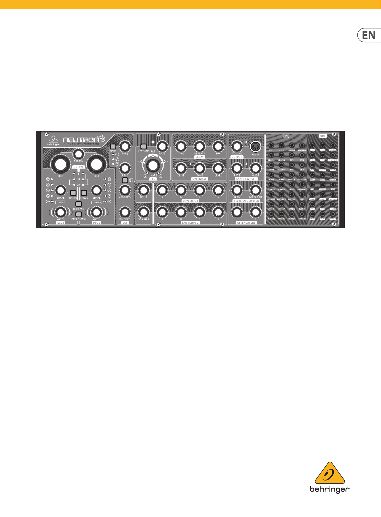
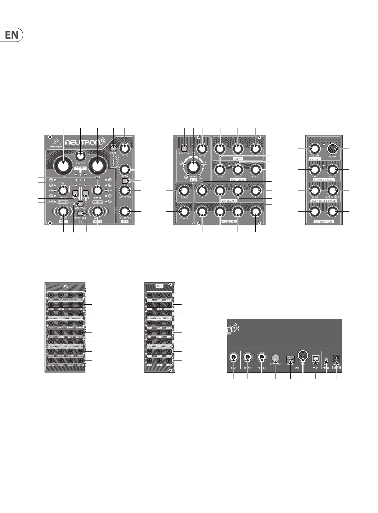
3. Controls
3.1 Top Controls
(1)
(6)
(7)
(8) (9)
(5)
(4)
(2) (3)
(17)
(10) (11)
(12)(13)
(14)
(15)
(16)
(44)
(42)
(43)
(37)
(38)
(39)
(40)
(41)
(36)(35)(34)(33)
(32)
(31)
(30)
(20)
(21)
(22)
(24) (25)(23)(18)
(26)
(27)
(28)
(29)
(19)
(45) (46) (47) (48)
(49) (50) (51) (52)
(53) (54) (55) (56)
(57) (58) (59) (60)
(61) (62) (63) (64)
(65) (66) (67) (68)
(69) (70) (71) (72)
(73) (74) (75) (76)
(77) (78) (79)
(80) (81) (82)
(83) (84) (85)
(86) (87) (88)
(89) (90) (91)
(92) (93) (94)
(95) (96) (97)
(98) (99) (100)
(101) (102) (103) (104) (105) (106) (107) (108)(109)
7 NEUTRON User Manual
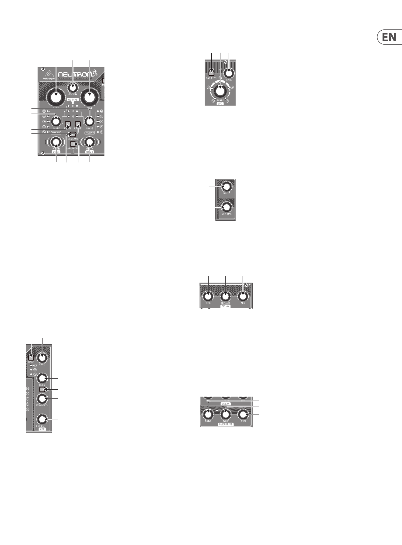
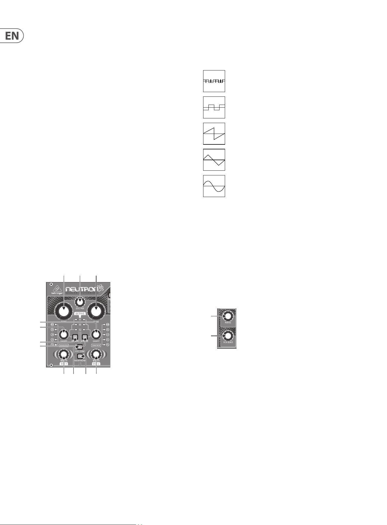
3.1.1 Oscillator Section VCO (Voltage Controlled
Oscillator)
(1) and (3) OSC TUNE - Adjusts the frequency of the oscillators.
(2) OSC MIX - Adjusts the blend between oscillator 1 and 2.
(4) and (5) OSC SHAPE - Adjusts the shape of the oscillator. Can be congured
to switch between xed waveforms or to blend continuously between
adjacent waveforms.
(6) and (7) OSC RANGE - Adjusts the pipe length of oscillators between
32/16/8. +/-10 octave mode enabled when all 3 LEDs are on.
(8) OSC SYNC - OSC 1 will restart the period of OSC 2, so that they will have the
same base frequency.
(9) PARAPHONIC - Allows the two oscillators to be independently pitched
when more than one MIDI note is played. If only one note is received, both
oscillators will play the same pitch.
(10) and (11) PULSE WIDTH (PW)- Sets the pulse width of oscillator pulse/tone
mod waveforms.
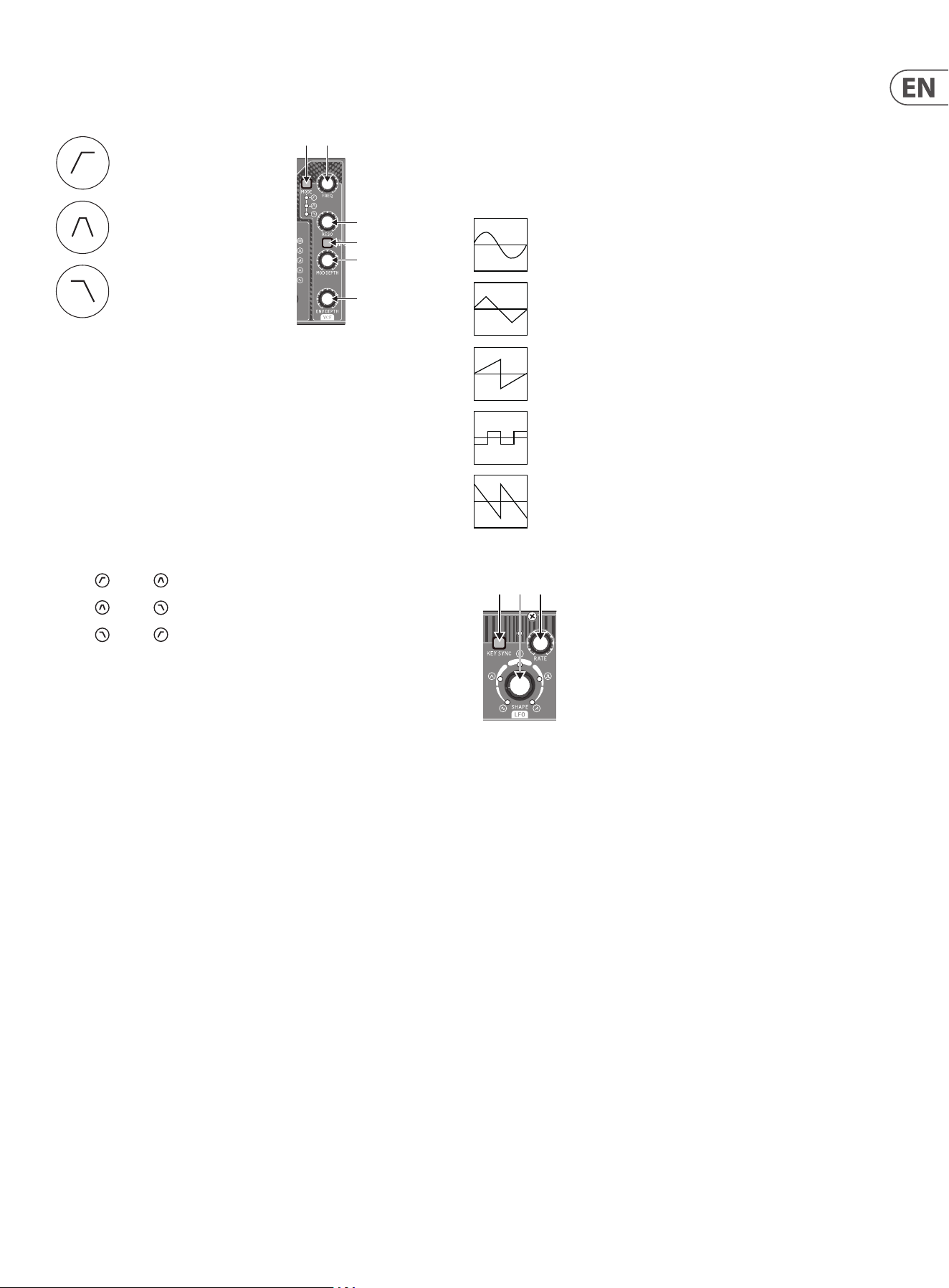
3.1.2 VCF Section (Voltage Controlled Filter)
(12) FREQ - Adjusts the cuto frequency of the VCF.
(13) MODE - Selects the lter type. Choose between High Pass Filter (HPF), Band
Pass Filter (BPF) and Low Pass Filter (LPF).
(14) RESO - Adjusts the resonance of the lter.
(15) KEY TRK - Applies keyboard tracking to the VCF.
(16) MOD DEPTH - Sets the depth of lter modulation from the FREQ MOD input.
(17) ENV DEPTH - Sets the depth of lter modulation from ENVELOPE 2.
(1)
(6)
(7)
(8) (9)
(5)
(4)
(2) (3)
(10) (11)
(17)
(12)(13)
(14)
(15)
(16)
3.1.3 LFO Section (Low Frequency Oscillator)
(18) SHAPE - Adjusts the shape of the LFO with the ability to blend between
waveforms.
(19) RATE - Adjusts the speed of the selected LFO waveform.
(20) KEY SYNC - Re-trigger the LFO phase with each new MIDI note.
3.1.4 Noise & VCA Bias
(21) NOISE LEVEL - Adjusts the amount of white noise injected into the lter.
(22) VCA BIAS - Opens or closes the VCA.
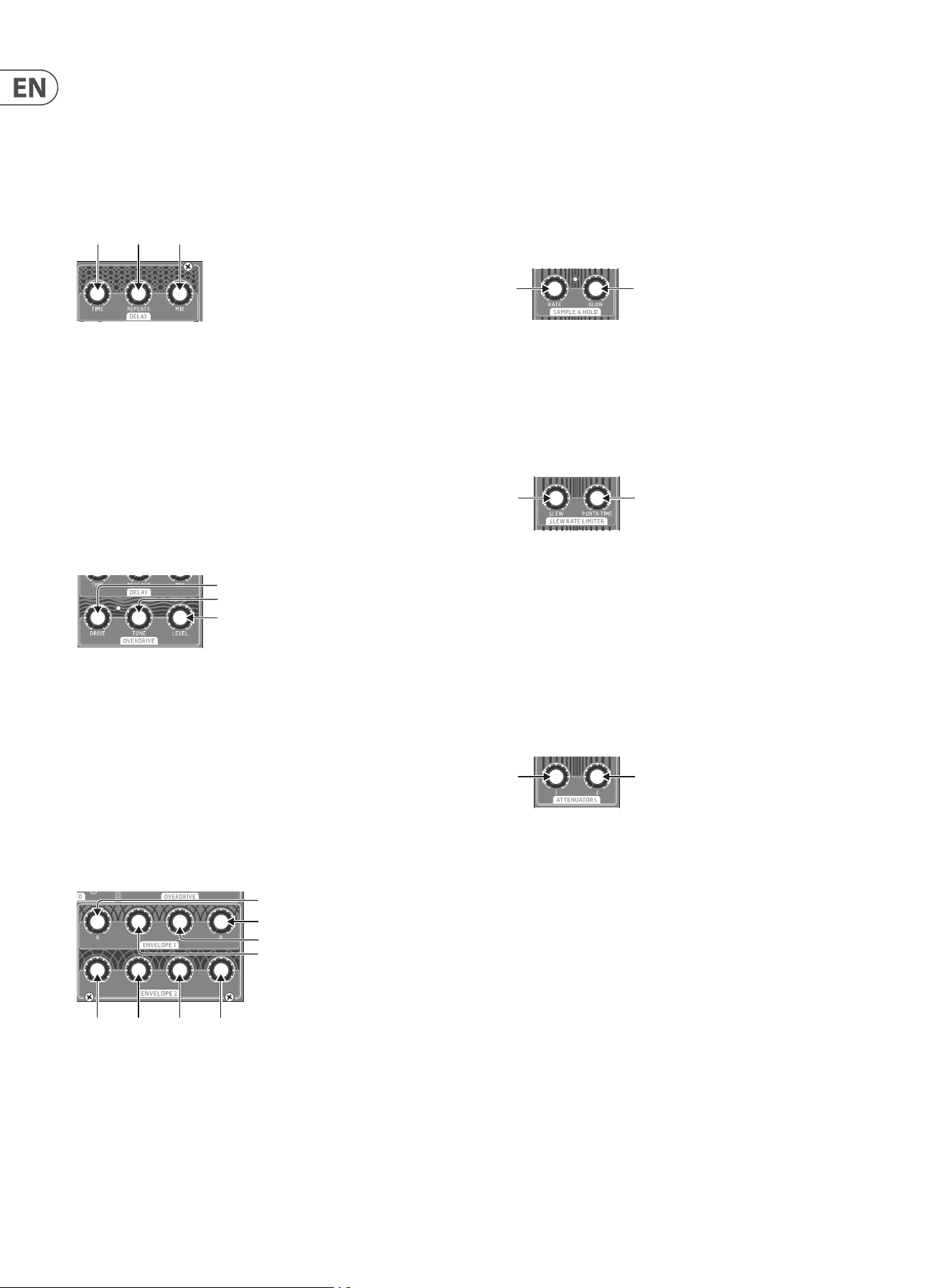
3.1.5 Delay Section
(23) TIME - Controls the rate of the delay. When the time control is fully to the
right, the longest delay time is set.
(24) REPEATS - Controls the number of repeats or echoes.
(25) MIX - Adjusts the wet/dry mix. When the mix control is turned fully to the
left, no eect will be heard. Turning the mix control fully to the right will
give you the delayed wet signal only. With the repeat control fully to the
right, repeats will be innite and keep building.
3.1.6 Overdrive Section
(26) DRIVE - Sets the amount of overdrive. The drive control can be used to add
subtle overdrive through to wild all-out distortion. Turn to the left for gentle
warming or turn to the right for more aggression and bite.
(27) TONE - Changes the timbre of the overdriven sound. Turning the tone to
the left boosts the lows to create rich warm sounds. Turning to the right
gradually thins out the low end and starts to boost the highs to create sharp
cutting sounds.
(28) LEVEL - Controls the volume of the overdrive output. When fully o you may
hear no audio at the output.
(20)(18) (19)
(21)
(22)
(24) (25)(23)
(26)
(27)
(28)
8 NEUTRON User Manual
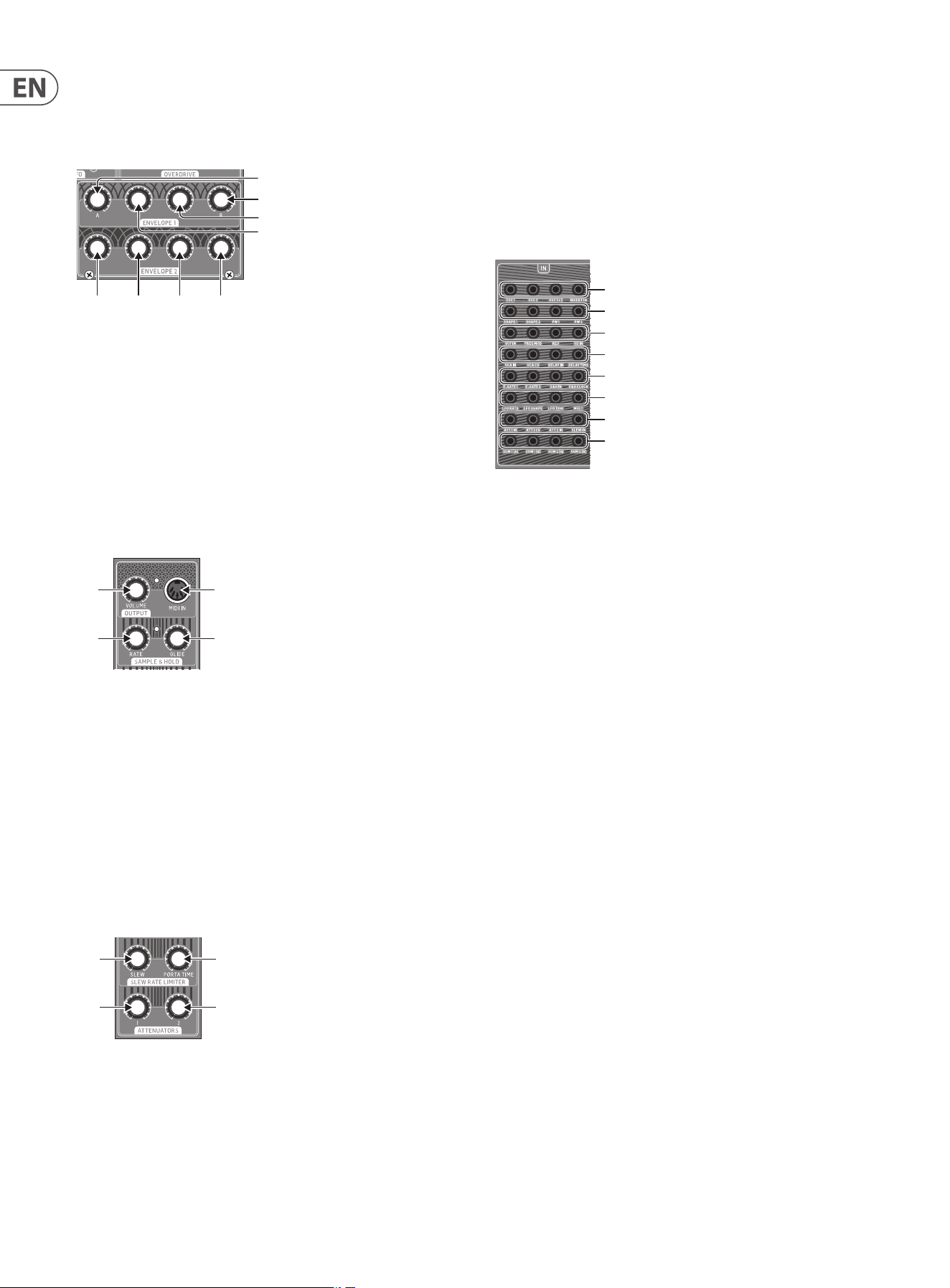
3.1.7 Envelope Section
Envelope 1
Envelope 1 is routed to the VCA CV by default.
(29) A [Attack] - Controls the attack time of the envelope.
(30) D [Decay] - Controls the decay time of the envelope.
(31) S [Sustain] - Controls the sustain level of the envelope.
(32) R [Release] - Controls the release time of the envelope.
Envelope 2
Envelope 2 is routed to the VCF lter cuto via ENV DEPTH control by default. See
17. ADSR knobs 33-36 function the same as 29-32.
3.1.8 Output Section
(37) VOLUME - Controls the output level of the synthesizer. The headphone
output is independent of the volume control and has its own control on the
back of the synthesizer.
(38) MIDI IN - Accepts incoming MIDI data from the selected MIDI channel.
3.1.9 Sample & Hold
Generates a random pattern based on the sample and hold clock.
(39) RATE - Controls the rate of the sample and hold clock.
(40) GLIDE - Sets the rate of change between sample values.
3.2 Slew rate Limiter & Attenuator Section
(41) SLEW - The Slew Limiter is used to limit the rate of change in a signal. This
function is sometimes referred to as 'Glide', 'Glissando', 'Lag Processing', or
'Portamento'. The amount of limitation is set by this control.
(42) PORTA TIME - Controls the rate of change between MIDI notes. The eect is
o when turned fully left and increases when turned to the right.
(36)(35)(34)(33)
(32)
(31)
(30)
(29)
(37)
(38)
(39)
(40)
(44)
(42)
(43)
(41)
(43) ATTENUATOR 1 - Used to reduce the amplitude of the input signal. ATT1 can
be controlled by a control voltage. See 58.
(44) ATTENUATOR 2 - Passive attenuator, reduces the amplitude of a signal.
Normalized patching routes the LFO to the oscillator Pulse Width inputs to
provide a Pulse Width Modulation (PWM).
3.2.1 Patch Bay
Input Patch Bay Section
(45) OSC 1 – OSC 1 pitch CV.
(46) OSC 2 – OSC 2 pitch CV.
(47) OSC1+2 – OSC 1 and 2 pitch CV.
(48) INVERT IN – The input signal is inverted at INVERT OUT. See 88.
(49) SHAPE 1 – OSC 1 Shape CV.
(50) SHAPE 2 – OSC 2 Shape CV.
(51) PW1 – OSC 1 PW CV.
(52) PW2 – OSC 2 PW CV.
(53) VCF – VCF signal input.
(54) FREQ MOD – VCF cuto frequency CV.
(55) RES – VCF resonance CV.
(56) OD IN – Overdrive signal input.
(57) VCA IN – VCA signal input.
(58) VCA CV – VCA CV.
(59) DELAY IN – Delay signal input.
(60) DELAY TIME – Delay time CV.
(61) E. GATE1 – Envelope 1 gate.
(62) E. GATE2 – Envelope 2 gate.
(63) S&H IN – Sample and Hold signal input.
(64) S&H CLOCK – Sample and Hold clock input.
(65) LFO RATE – LFO Rate CV.
(66) LFO SHAPE – LFO Shape CV.
(67) LFO TRIG – LFO Trigger input.
(68) MULT – MULT signal input. See 92/93.
(69) ATT1 IN – Attenuator 1 signal input.
(70) ATT1 CV – Attenuator 1 CV.
(45) (46) (47) (48)
(49) (50) (51) (52)
(53) (54) (55) (56)
(57) (58) (59) (60)
(61) (62) (63) (64)
(65) (66) (67) (68)
(69) (70) (71) (72)
(73) (74) (75) (76)
(77) (78) (79)
(80) (81) (82)
(83) (84) (85)
(86) (87) (88)
(89) (90) (91)
(92) (93) (94)
(95) (96) (97)
(98) (99) (100)
9 NEUTRON User Manual
(71) ATT2 IN – Attenuator 2 signal input.
(72) SLEW IN – Slew signal input.
(73) SUM1(A) – SUM 1 rst signal input. See 98.
(74) SUM1(B) – SUM1 second signal input. See 98.
(75) SUM2(A) – SUM 2 rst signal input. See 99.
(76) SUM2(B) – SUM 2 second signal input. See 99.
Output Patch Bay Section
(77) OSC 1 – Output of Oscillator 1.
(78) OSC 2 – Output of Oscillator 2.
(79) OSC Mix – Output of OSC 1/2 mix.
(80) VCF 1 – Main output of the lter.
(81) VCF 2 – Alternate output of the lter.
(82) OVERDRIVE – Overdrive output signal.
(83) VCA – Voltage Controlled Amplier output signal.
(84) OUTPUT – Main output signal, post delay.
(85) NOISE – Output of the white noise generator.
(86) ENV1 – Envelope 1 output.
(87) ENV2 – Envelope 2 output.
(88) INVERT – Inverted version of signal applied to INVERT IN. See 48.
(89) LFO – Output of the Bipolar LFO (-5 V to +5 V).
(90) LFO UNI – Output of the Unipolar LFO (0V to +5 V).
(91) S&H – Sample and Hold output signal.
(92) MULT 1 – Duplicate of signal applied to MULT IN. See 68.
(93) MULT 2 – Duplicate of signal applied to MULT IN. See 68.
(94) MIDI GATE – MIDI gate output.
(95) ATT1 – Output of Attenuator 1.
(96) ATT2 – Output of Attenuator 2.
(97) SLEW – Output of Slew.
(98) SUM1 – Summation of SUM 1(A+B).
(99) SUM2 – Summation of SUM 2(A+B).
(100) ASSIGN – Assignable output. See User Congurable Options & Features.
(45) (46) (47) (48)
(49) (50) (51) (52)
(53) (54) (55) (56)
(57) (58) (59) (60)
(61) (62) (63) (64)
(65) (66) (67) (68)
(69) (70) (71) (72)
(73) (74) (75) (76)
(77) (78) (79)
(80) (81) (82)
(83) (84) (85)
(86) (87) (88)
(89) (90) (91)
(92) (93) (94)
(95) (96) (97)
(98) (99) (100)
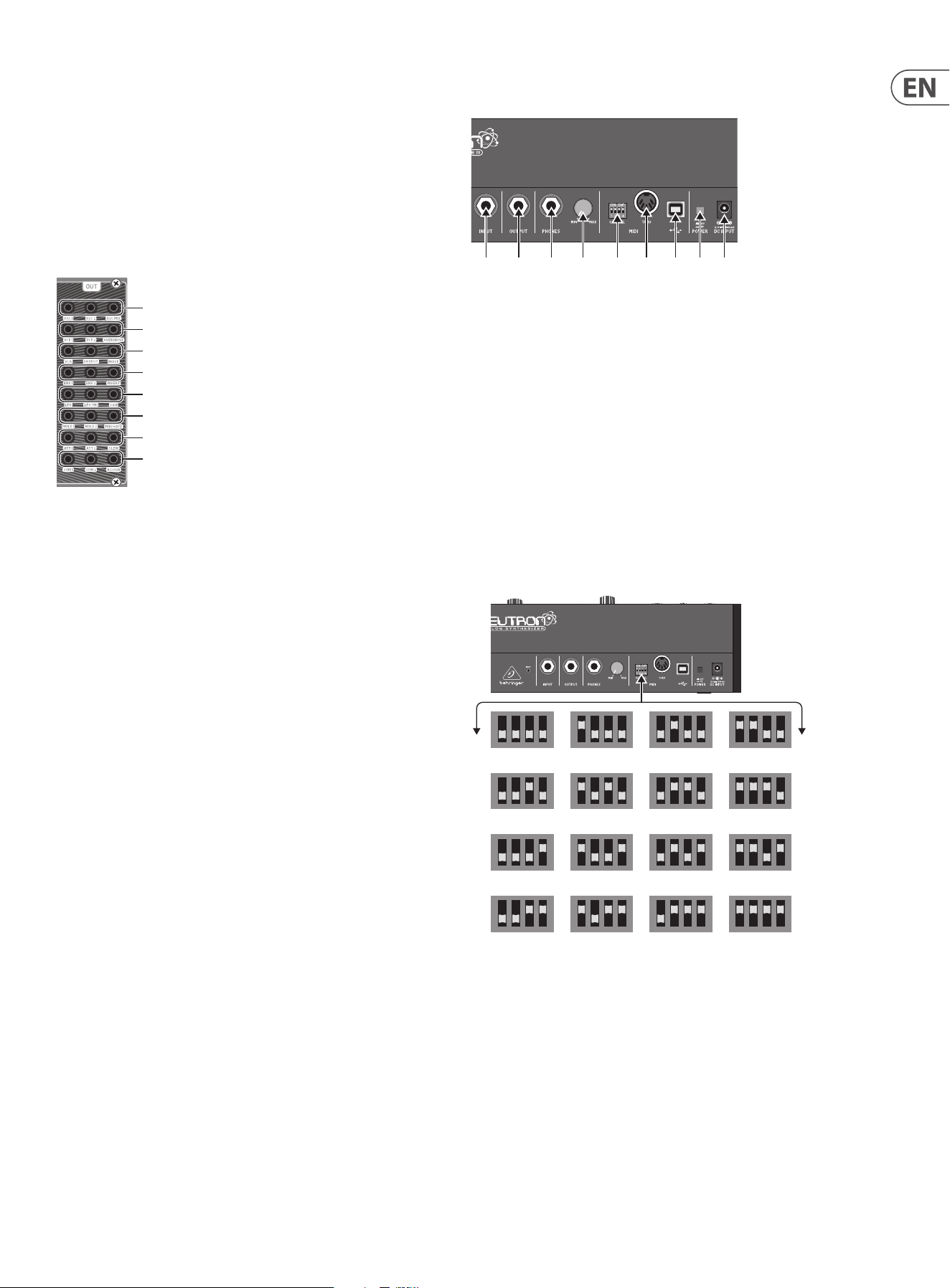
3.2.2 rear Panel
(101) INPUT – Mono unbalanced audio input using a ¼" (6.35 mm) jack cable for
processing external sound sources.
(102) OUTPUT – Connect to a mixer or audio interface using a ¼" (6.35 mm) mono
jack cable. Remember to turn your monitors/loudspeakers on last when
turning on your system and turn your monitors/loudspeakers o rst when
turning your system o.
(103) PHONES – ¼" (6.35 mm) jack connection to plug headphones in.
(104) PHONES LEVEL – Ensure the volume control is at minimum when putting
on headphones or when turning the synthesizer on or o.
(105) MIDI CHANNEL SELECTION.
Move the four dip switches to select the incoming MIDI channel for
the synthesizer.
(106) MIDI THRU – The 5-pin MIDI DIN connector is used to pass through MIDI
data received at the MIDI INPUT.
(107) USB PORT – Connects to a computer via standard USB cable. The Neutron
will display in your DAW as a class-compliant USB MIDI device, capable of
sending and receiving MIDI information.
(108) POWER SWITCH – Turns the synthesizer on and o. Make all audio
connections before powering on.
(109) POWER INPUT – Connect the supplied power supply only.
(101) (102) (103) (104) (105) (106) (107) (108)(109)
MIDI CHANNEL DIP SWITCH SETTINGS
1 2 3 4
5 6 7 8
9 10 11 12
13 14 15 16
10 NEUTRON User Manual
4. Overview
This overview will help you set up the Neutron analog synthesizer and briey
introduce its capabilities.
4.1 Connection
The Neutron has a ¼" (6.35 mm) mono jack output on the rear of the unit which
is also duplicated on the patch bay via a 3.5 mm output. Audio input is via a ¼"
(6.35 mm) mono jack on the rear panel. Please consult the connection set-up
guide for examples (8.1).
Caution: Do not overload the 3.5 mm inputs. They can only accept the correct
level of voltages as shown in the specication tables later in this manual. The
3.5 mm outputs should only be connected to inputs capable of receiving the
output voltages. Failure to follow these instructions may damage the Neutron or
external units.
4.2 Software Setup
The Neutron is a USB Class Compliant MIDI device, and so no driver installation
is required. The Neutron does not require any additional drivers to work with
Windows and MacOS.
4.3 Hardware Setup
Make all the connections in your system. Use the rear panel MIDI switches to
set the Neutron to a unique MIDI channel in your system. Connect an external
keyboard with MIDI output directly to the Neutron MIDI IN 5-pin DIN type input
or via MIDI over USB. Apply power to the Neutron using the supplied power
adapter only. Ensure your sound system is turned down. Turn on the Neutron rear
panel power switch.
4.4 Oscillator Section
Each oscillator has a tune control which gives approximately +/-1 octave range
in 8/16/32 modes or a range from 0.7 Hz to over 50 kHz when all range LEDs are
illuminated which is around +/-10 octaves.
The OSC MIX control is used to blend between the two oscillators to create rich
harmonic sounds.
(1)
(6)
(7)
(8) (9)
(5)
(4)
(2) (3)
(10) (11)
You can adjust the SHAPE control for each oscillator to select dierent
waveforms, if in blend mode, the waveforms will morph into one another in a
smooth transition.
The ve oscillator shapes are:
The P. WIDTH aects the rst two wave shapes, TONE MOD and SQUARE WAVE.
When OSC SYNC is engaged, oscillator 1 tracks the MIDI note and provides a
reference to reset the period of oscillator 2.
When the PARAPHONIC switch is engaged, it allows the two oscillators to be
independently pitched when more than one MIDI note is played simultaneously.
If only one note is played, both oscillators will be driven at the same pitch.
The NOISE control injects white noise into the lter, which can be used to add
another texture to the sound. Noise can be used to create percussive sounds
when used with short VCA envelope settings.
VCA Bias is used to control the VCA. It allows the user to 'open' the VCA without
triggering the envelope (e.g. with a MIDI note), allowing audio to
sound continuously.
Tone Mod
Square/Pulse
Sawtooth
Triangle
Sine
(21)
(22)
11 NEUTRON User Manual
4.5 Filter Section
The Neutron has a powerful 12 dB lter with three modes available:
The mode button steps through each lter mode.
The FREQ control sets the lter cuto frequency. The RESO control adjusts the
resonance of the lter. When the resonance control is set to at, or close to,
maximum the VCF will become self-resonant and produce a sine wave tuned to
the cuto frequency of the lter. This tone can be used in sound creation and
played in tune with the oscillators by activating KEY TRACK and tuning the VCF
using the FREQ control.
By default, the LFO is patched through the FILTER DEPTH control. This enables
modulation of the lter frequency using the LFO. The VCF has a second output
which is accessible from the patch bay (VCF 2). VCF 2 mode is determined by the
select VCF mode. The relationship is:
Mode =
, VCF2 =
Mode =
, VCF2 =
Mode =
, VCF2 =
This allows for additional lter modes. For example, a notch lter can be created
when the lter mode is set to by summing VCF 1 and VCF 2, then patching the
summed output into OD IN.
KEY TRACK applies keyboard tracking to the VCF.
This sets the lter cuto frequency based on the latest MIDI note received. The
base cuto frequency is set using the FREQ control with MIDI notes increasing the
cuto frequency relative to the note being played. Additionally, this allows the
lter to be played like an oscillator when the resonance control is turned up.
High Pass Filter (HPF)
Band Pass Filter (BPF)
Low Pass Filter (LPF)
(17)
(12)(13)
(14)
(15)
(16)
4.6 LFO Section
The Neutron LFO has a frequency range of 0.01 Hz to 10 kHz. This allows low
frequency modulation up to audio rate modulation using the LFO.
The Shape control sets the type of LFO waveform. When selecting the LFO
waveform, the control can be set to select between xed types or to blend
between wave shapes. The ve LFO shapes are:
With KEY SYNC engaged, the LFO is re-triggered when a MIDI note is received.
Sine
Triangle
Sawtooth
Square
Reverse Sawtooth
(20)(18) (19)
12 NEUTRON User Manual
4.7 Delay Section
The Neutron has an impressive analog bucket brigade delay section. Delay times
of 24 ms to 640 ms can be set. Eects from long dub delays to extreme chorusing
can be created. Set the MIX control at 12 o’clock. Then try turning the RATE
control fully left with the REPEAT control to the right a little for a long dub style
sound. Chorus eects can be created by modulating short delay times with an
LFO applied to the DELAY TIME input via one of the ATTENUATORS.
4.8 Overdrive Section
The overdrive section can be used to add subtle warmth through to extreme
distortion by using an analog soft clipping circuit. Turning the DRIVE control to
the right increases the amount of distortion, adding rich harmonics. The TONE
control shapes the sound of the overdrive. To the left, high-end ltering is applied
to take away the harsh edge. When the TONE control is turned to the right the
low end is ltered out to give a brighter sound. As DRIVE level is increased, the
LEVEL control can be utilized to turn down the volume of the synthesizer, without
aecting the drive or tone of the sound.
NOTE: If the level control is all the way down it is possible that no sound
will be heard.
4.9 Envelope Section
The Neutron contains two ADSR (Attack, Decay, Sustain, Release) envelopes. Both
envelopes are triggered when a MIDI note is received unless the E.GATE 1/2 inputs
are used.
ENVELOPE 1 is routed to the VCA CV by default. This allows the signal to pass
through the unit when a MIDI note is being played and closes the VCA when no
note is being played.
ENVELOPE 2 is routed to the VCF, via the ENV DEPTH control, by default. This can
be used to create lter sweeps when a MIDI note is being played. Try dierent
combinations of slow and fast settings to create dierent sounds and textures.
(24) (25)(23)
(26)
(27)
(28)
(36)(35)(34)(33)
(32)
(31)
(30)
(29)
4.10 Sample And Hold
The sample and hold function generates a random, stepped waveform by taking
a sample of the input signal. The sample rate is governed by the RATE control or
the SH CLOCK input. This generates a distinctive, bubbling random waveform that
can be used to modulate other synth parameters. Its random nature makes it well
suited to sci- eects. Try patching S&H to OSC 1&2 to modulate the oscillator's
pitch. The distinctive gurgling eect can be heard throughout sci- movies.
The GLIDE control limits the rate of change between samples, allowing smooth
transitions between sample values.
4.11 Slew rate Limiter
PORTA TIME is the amount of time taken to transition between two MIDI notes.
This feature can be used to add a pleasing musical slide into your sounds.
The SLEW Limiter is used to limit the rate of change of a signal. For example, Slew
can be used to add Portamento to pitch CVs generated from an
external sequencer.
4.12 Attenuators
ATTENUATOR 1 is an additional VCA which can be used to reduce the amplitude
of the input signal based on the Att1 CV control or the attenuator 1 front panel
control (43).
ATTENUATOR 2 - Reduces the amplitude of a signal based on the attenuator
2 control (44). The BIPOLAR LFO output is routed to the attenuator 2 input
by default.
Note: The attenuator 2 output is also routed to P.WIDTH 1 and P.WIDTH 2 controls
by default.
4.13 Pitch Bend messages
The Neutron responds to pitch bend messages via USB MIDI or the MIDI IN and
is set to +/-2 semitones as a default. It is possible to change this with SysEx
Messages or via the Neutron App.
(37)
(38)
(39)
(40)
(44)
(42)
(43)
(41)
(44)
(42)
(43)
(41)
13 NEUTRON User Manual
5. User Congurable
Options & Features
All features in this manual require software version V2.0.X or higher in
order to function correctly. Please visit the www.behringer.com to nd
the latest software version.
5.1 Software Version
Press and hold OSC SYNC and PARAPHONIC until all 3 OSC1 octave LEDs light up.
The LEDs will then ash out the software version, just count the ashes. The
version is of the form <Major>. <Minor>. <Build number>. Major is ashed on
the 8' LED, minor on the 16' LED & build number on the 32' LED. All 3 OSC1 octave
LEDs will light up again to indicate the end of the output.
5.2 Assignable Output
It is possible to select the source of the ASSIGN output jack. To change the source
press & hold the OSC SYNC button until both the RANGE buttons are ashing.
The currently selected assignable output is indicated by the ashing LFO shape
LED - the available options are (clockwise from the sine shape):
OSC 1 CV
OSC 2 CV
“Note On” velocity
Modwheel
Aftertouch
Use the two range buttons to change the selected output. When you're done,
press and hold the OSC SYNC button until the RANGE buttons stop ashing.
The currently selected assignable output value will be stored and will persist
across power cycles.
5.3 Envelope retriggering
Enter the Assignable Output mode (see above). The KEY TRK button toggles
the retriggering mode. When the KEY TRK LED is on, retriggering is enabled
and vice versa.
5.4 OSC & LFO Shape mix Blended or Switched
It is possible to either blend or switch the OSC and LFO shape. This feature is an
incredibly powerful, unique sound creation tool. For OSC1, press and hold the
OSC1 RANGE button (this will enter the tuning feature). The PARAPHONIC button
will ash if shape mixing is disabled, or it will throb if shape mixing is enabled.
Press the PARAPHONIC button to toggle the shape mix state. Press and hold the
OSC1 RANGE to leave this mode. Similarly, for OSC2 shape mixing press and hold
OSC2 RANGE; for LFO shape mixing press and hold LFO KEY SYNC.
5.5 Tuning
The Neutron will self-calibrate at start up. An additional "tune" feature is
designed to allow the user to manually tune the oscillators to the last played
MIDI note. To tune OSC1 or OSC2 to the nearest ‘C’ note, press and hold the
appropriate RANGE button until the octave LED starts to ash. Play a MIDI note.
The LFO shape LEDs will display the tuning; turn the TUNE control until only the
descending saw LED is lit. That oscillator will now be playing a 'C'. This enables
the accurate tuning of intervals. For example, play an 'F' note, then tune as
above. That oscillator is now playing a fth above the root note. To exit tuning
mode, press and hold the RANGE button until the octave LED stops ashing.
This is available in +/-10 octave mode (note that the long period of very low
notes means that the tuning feature appears to be unresponsive).
5.6 Tune Pot Bypass
Press and hold OSC (1 or 2) RANGE and PARAPHONIC buttons until the selected
OSC octave LED starts to ash. This indicates that the tune pot for that OSC is
now inactive and all notes played are in tune. Press and hold OSC RANGE and
PARAPHONIC buttons again to leave this mode. The LED will return to solid to
indicate that the tune pots are in circuit.
5.7 LFO mIDI Clock Sync
The LFO will sync to the beat when receiving MIDI clock (it does nothing with
MIDI time code). The LFO rate position determines the clock multiplier-divider.
The LFO divider values are, from counter clock wise to clockwise:
4/1, 3/1, 2/1, 3/2, 1/1, 1/2, 3/8, 1/3, 1/4, 1/5, 3/16, 1/6, 1/7, 1/8,
3/32, 1/12, 1/16, 1/24, 1/32, 1/48, 1/64.
5.8 mIDI Note range
The supported MIDI note range is 24 (C1) to 96 (C7) inclusive. Notes outside of this
range will still trigger the Neutron. MIDI notes 0-23 will trigger note 24 (C1) note.
MIDI notes 97-127 will trigger note 96 (C7).
5.9 LFO Depth
The depth of the LFO can be changed by long pressing the KEY SYNC button.
Now the LFO shape LED wheel will indicate the current LFO depth: 1% to 100%
(64 steps). Use the range buttons as + and - buttons. Pressing and holding
the range buttons will continually adjust the depth rather than having to step
through each value. Changing the LFO depth allows you to add subtle movement
to a sound. For example, applying the LFO to lter depth.
5.10 LFO One-shot mode
It is possible for the LFO to be triggered once. First ensure KEY SYNC is active. One
shot mode will only work if LFO KEY SYNC is on. Then press and long hold KEY
SYNC and use the VCF mode buttons to select the mode.
The VCF mode LEDs will indicate the LFO one-shot mode:
HPF
= Disabled
BPF
= Enabled
You can enable/disable the LFO one shot staccato or legato mode, with a press of
the KEY TRACK button. Enabling the re-trigger LFO on overlapping notes is Legato
mode. Disabling the re-trigger LFO is staccato mode. This gives you two dierent
ways to play the Neutron musically.
5.11 LFO Key rate
Long press KEY SYNC to enter the LFO Sub Menu, then press and hold the KEY TRK
button whilst playing a note. This will set the selected note as the LFO Base note.
Now when you play up and down the keyboard the LFO speed will either speed
up (double the base LFO rate for each octave above the base key) or slow down
(halving the LFO rate for each octave below the base key). This function is great
for creating unusual modulations and textures.
5.12 LFO mIDI Clock Sync
Long press LFO KEY SYNC. The OSC SYNC button LED will now indicate the MIDI
clock sync mode. On - LFO rate sync'd to MIDI clock. O - LFO rate free-running.
Use this function to sync the LFO to your DAWs MIDI Clock so the Neutron’s LFO
plays in time with your song depending on the chosen settings.

14 NEUTRON User Manual
5.13 VCF mod Source
Long Press VCF Mode then the LFO shape LED wheel will indicate the current mod
source selection:
Not used
Disabled
Note-On velocity
Mod-wheel (CC1)
Aftertouch
Press RANGE +/- to select the output.
Press VCF MODE to toggle between setting the mod source & depth.
This gives you the power to play the lter via velocity changes or use Aftertouch
to open up the lter after a note is played.
5.14 VCF mod Depth
Long Hold lter (VCF) MODE, Press VCF MODE to toggle between setting the
mod source & depth. When in VCF mod depth mod the LFO shape LED wheel will
indicate the current VCF mod depth: 1%−100% (64 steps)
Press RANGE +/- to select the output of depth. Adjusting the VCF Mod depth
allows a sound to have a more restricted lter sweep which may be used to
create interesting eects.
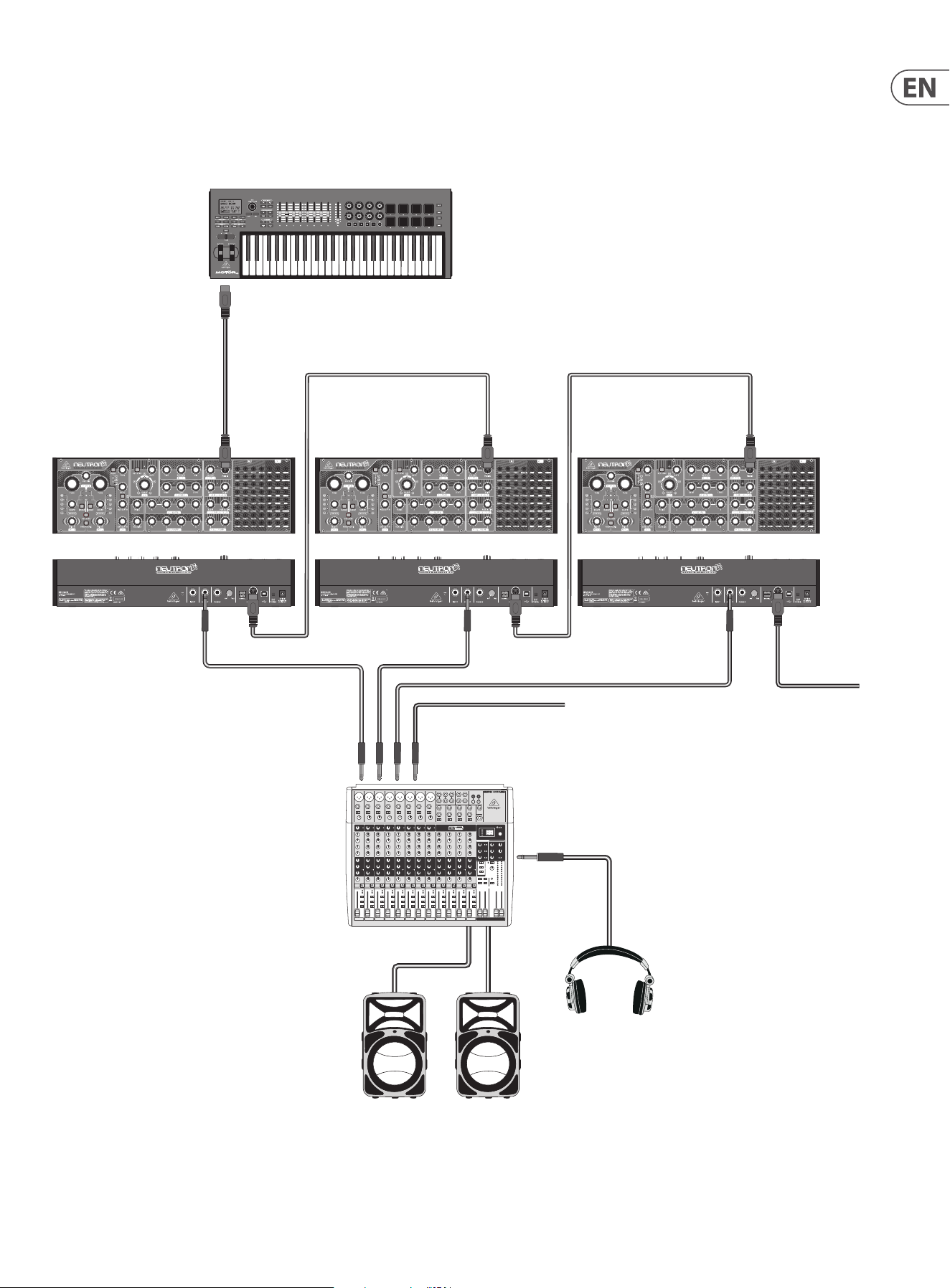
5.15 Poly-Chaining
If you have multiple Neutron units, you can connect them in a ‘Poly Chain’ to
produce polyphonic sounds. The Neutron works by sending unhandled notes
to the next in the chain. When the chain runs out, the notes are dropped
(i.e. not played). The rst Neutron plays the rst played note, the second plays
the second, the third plays the third etc. Note that a Neutron in Paraphonic mode
will handle 2 notes. Each Neutron must have the same MIDI channel number
set using the rear panel switches. The Poly Chain connections are shown in the
diagram. Set the Poly Chain ON for all Neutrons. The last Neutron in the chain can
either be set to Poly Chain on or o depending on how you would like the MIDI
information to be handled. If Poly Chain is on, the last Neutron will act as if it is
sending the next played note over the maximum number of notes played to the
next device in the chain, and the note will not be heard or dropped. If Poly chain
is o for the last Neutron, the next played note over the maximum number of
notes will steal the last played note from the last Neutron.
To toggle Poly Chain mode, press and hold the PARAPHONIC button for 2 seconds.
The LED will repeatedly ash (once when in mono mode - twice when in duo
mode). A short press on the PARAPHONIC button will still toggle the PARA/DUO
mode. Hold PARAPHONIC to exit. If you are only using one Neutron, make sure the
Poly Chain is OFF.
5.16 Note Priority
Note priority can be set by long pressing the OSC SYNC button. The VCF mode
LEDs will now indicate the note priority. Note priority allows dierent playing
styles and eects to be used creatively.
HPF = high note priority
BPF
= last note priority (default)
LPF
= low note priority
5.17 Pedal mode
Press & hold OSC2, then pressing KEYTRK will toggle the state of of the mode.
When the KEYTRK LED is lit - OSC 2 will play the last note played before Pedal
Mode was enabled with each new note played. This starts when any
key is pressed.
When KEYTRK LED is not lit - OSC2 will behave normally.
5.18 Features via Sysex and Neutron app only
Autoglide
Autoglide sets the number of semitones that the start of the note 'glides through'
for the selected note. This can be a + value (so the note glides down), or a - value
(so the note glides up). It is played as a smooth and linear increase or decrease
in pitch rather than a semitone step-change. The speed of the glide is set by the
Porta control.
When activated the Neutron will now glide up/down +/-12 semitones. If notes
overlap (played legato) this will allow easy programming of 303 style patterns
using a typical piano roll editor in a DAW.
Set pitch bend range
Select the pitch bend range from 0 to +/-24 semitones (two octaves).
Key split
Create a key split at the desired note. Notes played below the split point will
trigger oscillator 1 and notes above will trigger oscillator 2.
LFO shape order
Populate the 5 LFO locations with any of the 5 available wave shapes. The order
will directly match the order of the LFO control on the unit going clockwise.
LFO phase
Select the start position of the waveform each time the LFO is triggered. This can
be set for each of the 5 LFO positions independently. This can be used to create
unusual modulations and textures.
Setting midi channel (auto disable dip switches)
Set the MIDI channel without the need to access the MIDI DIP switches on the
back of the unit. Setting the channel this way automatically disables the DIP
switches. This function is useful when using the Neutron in a separate Eurorack
set up rather than its factory supplied case.
15 NEUTRON User Manual
MIDI IN MIDI IN
MIDI THRU
MIDI IN
MIDI THRU
MIDI THRU
From next Neutron
To next Neutron
MIDI Keyboard
Mixing console
Active Loudspeakers
Headphones
Poly chain system
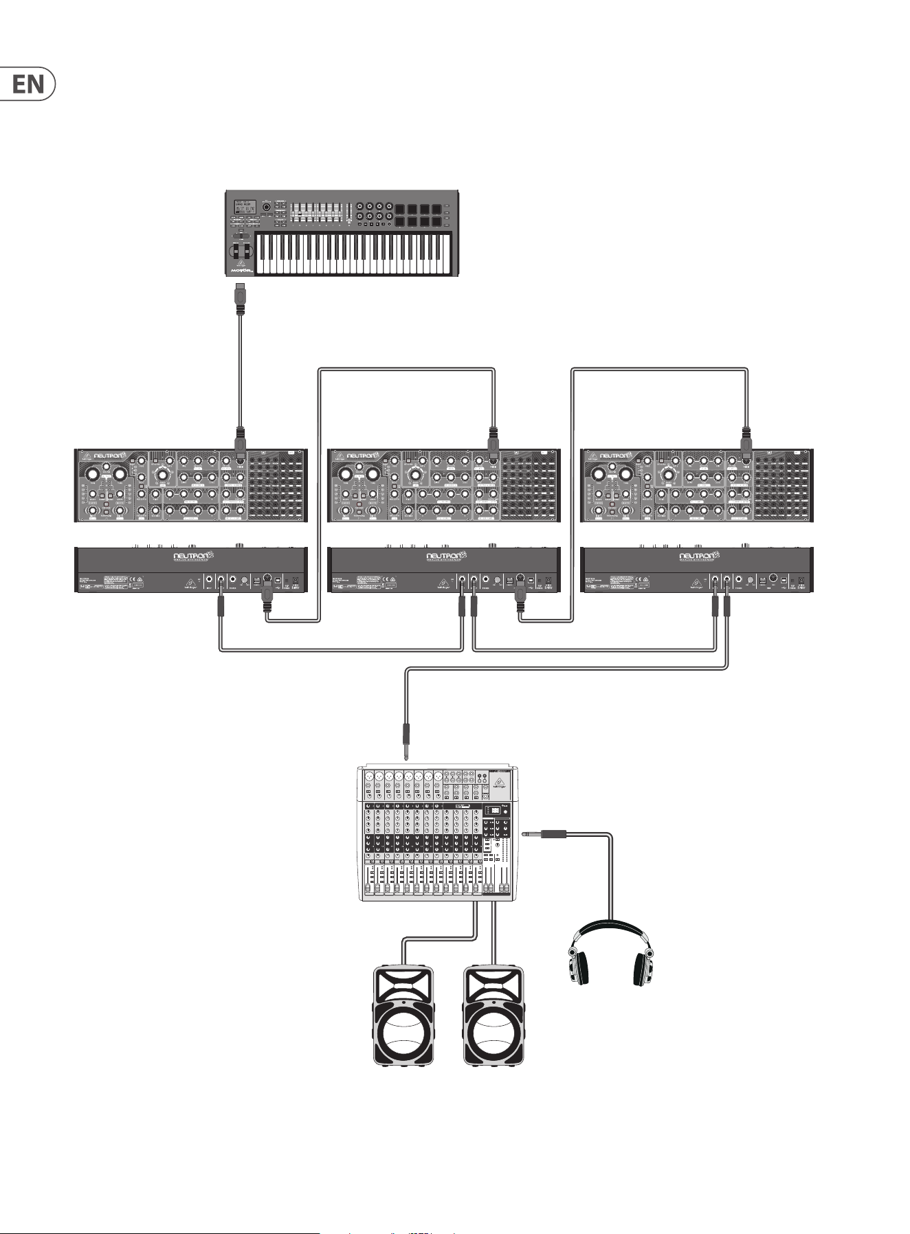
16 NEUTRON User Manual
MIDI IN MIDI IN
MIDI THRU
OUTPUT INPUT
MIDI IN
MIDI THRU
MIDI THRU
MIDI Keyboard
Poly chain system using Neutron’s audio input
Mixing console
Active Loudspeakers
Headphones
OUTPUT
INPUT
OUTPUT
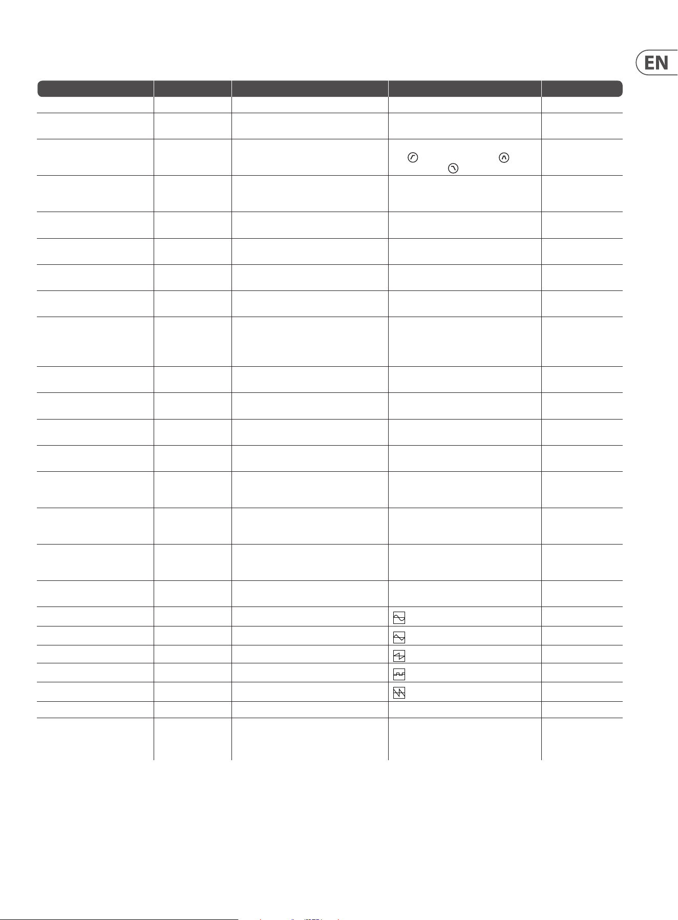
17 NEUTRON User Manual
Advanced Features Access Action Result Exit
Change Assignable Output (ASSIGN) Hold OSC SYNC Use RANGE buttons to change Output function LFO shape displays selected option. Hold OSC SYNC
Envelope Retriggering Hold OSC SYNC The KEY TRK button toggles the retriggering mode When the KEY TRK LED is on - retriggering
is enabled
Hold OSC SYNC
Note Priority Hold OSC SYNC Press theVCF modebutton to cycle through the
options
TheVCF modeLEDs will indicate the note priority.
(HPF
) = high note priority - (BPF ) = last
note priority - (LPF ) = low note priority.
Hold OSC SYNC
Restore Defaults Hold PARAPHONIC,
KEY TRK and OSC SYNC
on power on.
The process only takes a moment. When you see
the LED sweep you can let go of the buttons
Defaults restored None
OSC 1 Shape (Blend or Switched) Hold OSC1 RANGE PARAPHONIC will either throb or ash. Push to
toggle mode
OSC 1 Shape mode will toggle. Blend or switch Hold OSC 1 RANGE
OSC 2 Shape (Blend or Switched) Hold OSC2 RANGE PARAPHONIC will either throb or ash. Push to
toggle mode
OSC 2 Shape mode will toggle. Blend or switch Hold OSC 2 RANGE
OSC 1 Tuning Hold OSC1 RANGE LFO shape LEDs shows tuning with respect to the
last played MIDI note
Top center LFO Shape LED indicates that the
oscillator is in tune
Hold RANGE 1
OSC 2 Tuning Hold OSC2 RANGE LFO shape LEDs shows tuning with respect to the
last played MIDI note
Top center LFO Shape LED indicates that the
oscillator is in tune
Hold RANGE 2
Pedal Mode Hold OSC2 KEYTRK will toggle the state of of the mode When the KEYTRK LED is lit - OSC 2 will play the
last note played before being enabled.
When KEYTRK LED is not lit - OSC2 will
behave normally
Hold OSC2
Poly Chain mode Hold PARAPHONIC The LED will ash once in mono mode - twice
quickly in duo mode
Poly-Chain mode toggled on/o Hold PARAPHONIC
LFO (Blend or Switched) Hold LFO KEY SYNC PARAPHONIC will either throb or ash. Push to
toggle mode
LFO Shape mode will toggle. Blend or switch Hold LFO KEY SYNC
LFO Depth Hold LFO KEY SYNC Press RANGE+/- to select the output depth. LFO shape LED wheel will indicate the current LFO
depth: 1% to 100% (64 steps)
Hold LFO KEY SYNC
LFO one-shot mode Enable KEY SYNC,
then Hold LFO KEY SYNC
Enable KEY SYNC. Press the VCFMODEbutton to
cycle through the options.
The VCF mode LEDs will indicate the LFO one-shot
mode: HPF = Disabled - BPF = Enabled -
Hold LFO KEY SYNC
LFO envelope retrigger Hold LFO KEY SYNC theKEY TRKbutton LED will indicate the LFO
retrigger mode
On - LFO will retrigger for overlapping notes
(staccato), O - LFO will not retrigger for
overlapping notes (legato).
Hold LFO KEY SYNC
LFO key rate track Hold LFO KEY SYNC Long pressKEY TRKwhilst playing a note to set
that note as the LFO base note. Long pressKEY
TRKwhen no note is played to disable
Sets that note as the LFO base note Hold LFO KEY SYNC
LFO MIDI Clock Sync Hold LFO KEY SYNC PressOSC SYNCto toggle the state TheOSC SYNC button LED will indicate the MIDI
clock sync mode. On - LFO rate sync'ed to MIDI
clock. O - LFO rate free-running
Hold LFO SYNC
VCF mod source Hold lter (VCF) MODE Press VCF MODE to toggle between setting the mod
source & depth
LFO shape LED wheel will indicate the current
mod source selection:
Hold lter (VCF) MODE
Not used
Disabled
Note-On velocity
Mod-wheel (CC1)
Aftertouch
Press RANGE+/- to select the output
VCF mod depth Hold lter (VCF) MODE PressVCF MODEto toggle between setting the mod
source & depth
LFO shape LED wheel will indicate the current VCF
mod depth: 1%−100% (64 steps)
Hold lter (VCF) MODE Press RANGE +/- to select the amount of depth
18 NEUTRON User Manual
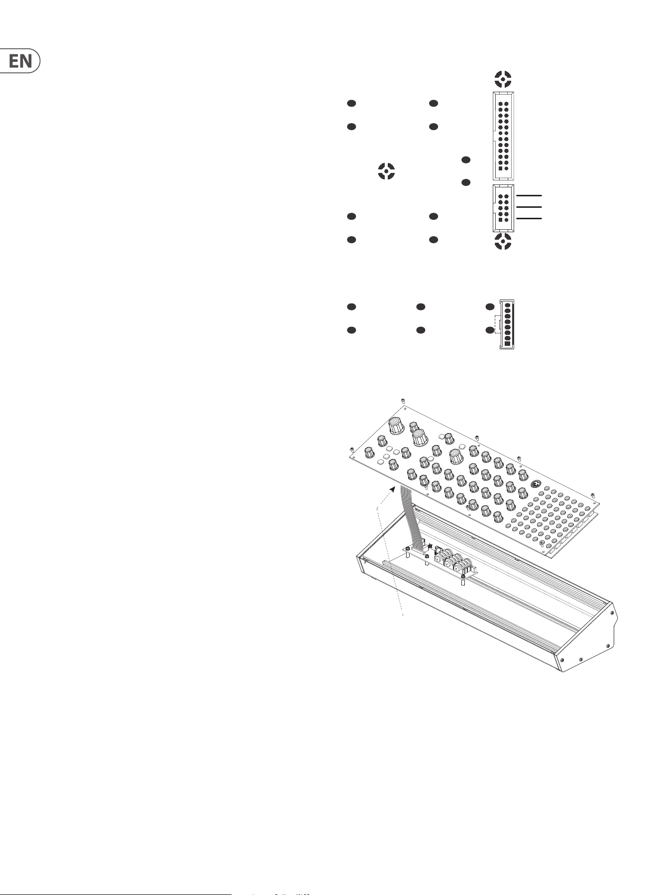
6. Eurorack Installation
The Neutron synthesizer can be taken out of its factory chassis and tted into a
standard Eurorack case (not supplied).
We recommend that this procedure is undertaken only by an experienced service
technician, to prevent personal injury, or damage to the unit. The Eurorack case
will need its own suitable power supply unit to power the Neutron synthesizer.
A 10-pin connector on the rear of the main PCB of the Neutron allows the
+12 VDC power supply connection to be made. A 10-pin to 16-pin adapter ribbon
cable is supplied to connect to your power supply.
Before proceeding, make sure that your power supply is capable of supplying
+12 VDC, 1 Amp.
Make sure that the connections using the supplied adapter cable will supply the
ground and power to the correct pins.
6.1 Procedure
Follow all steps in the order in which they are presented.
1. Disconnect the power cord and all other connections to the Neutron.
2. Undo the 8 screws on the top panel as shown. There is no need to undo any
other screws.
3. Carefully lift the top panel assembly and turn it over so the PCB is facing
upwards. Be careful not to pull on the cable from the lower side of the main PCB.
4.Disconnect the 24-pin cable from the side of the main PCB of the Neutron, X58
and remove the assembly from the chassis.
5. Store the chassis assembly and the power supply adaptor in a dry safe place.
6. Securely connect the 10-pin end P1 of the supplied adapter cable to connector
X59 on the Main PCB of the Neutron.
7. Make sure your power supply is turned o and disconnected from the AC mains.
8. Make sure that your power supply will supply a 12 V voltage to the pins of the
connector, as shown in the diagram.
9. Securely connect the 10-pin end P2 of the supplied adapter cable to your power
supply, and double check all connections are correct.
10. Securely install the Neutron Synthesizer into your Eurorack, using 8 screws in
the front panel.
11. Perform a full system test and safety test before using the Neutron.
12. The 3.5 mm OUTPUT connector on the top panel is used instead of the rear
output which is no longer present.
+12 VDC
No Connection
Pins 3 to 8 Ground
X58
X59
X60
Disconnect from
Main PCB
19 NEUTRON User Manual
7. Software Update & Calibration
7.1 Software Update
The Neutron DFU (Device Firmware Upgrade) updater can be downloaded by
going to www.musictribe.com
Please follow the steps documented in the release notes accompanying
the update.
7. 2 Assign Out Calibration
This calibration has been carried out by the factory at the manufacturing stage
but instructions are described here if needed.
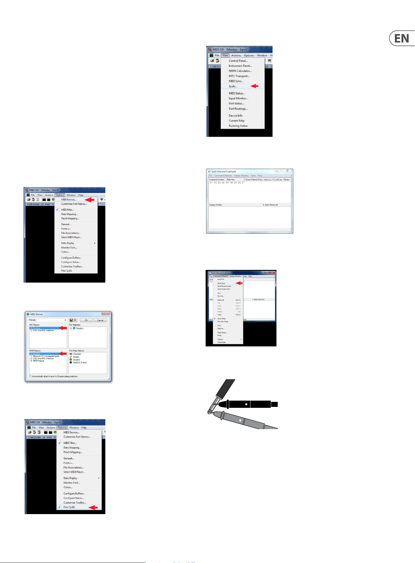
For this, you'll need a 3.5 mm mono patch cable, a digital voltmeter, and MIDI-OX
installed on your PC.
1. Insert the patch cable into the ASSIGN output on the Neutron front panel.
2. Run MIDI-OX on your computer. Go to OPTIONS > MIDI DEVICES.
3. Select Neutron as the MIDI IN and MIDI OUT
4. Make sure "Pass SysEx" at the bottom of the Options drop-down menu
is ticked.
5. In the VIEW menu, select SysEx...
6. In the Command Window, enter the SysEx command to be sent to the Neutron.
For ASSIGN out calibration at 1 V, the command is: F0 00 20 32 28 7F 10 20 F7
7. In the Command Window drop-down menu, select Send SysEx. The Sysex
command will be sent to the Neutron. Both 8' octave range LEDs will be ashing
to indicate the Neutron is in ASSIGN out 1 V calibration mode.
8. Measure the voltage on the patch cable attached to the ASSIGN out and adjust
until it reads 1 V +/- 0.001 V.
9. To increase the voltage send the Sysex command F0 00 20 32 28 F7 10 23 F7.
To decrease the voltage, send the Sysex command F0 00 20 32 28 F7 10 22 F7.
Repeat until the voltage reads 1 V +/- 0.001 V. Then move on to step 10.
10. Send the Sysex command for ASSIGN out calibration to the Neutron at 4 V.
The command is F0 00 20 32 28 7F 10 21 F7.
Both 32' octave range LEDs will be ashing to indicate the Neutron is in ASSIGN
out 4 V calibration mode.
11. Repeat step 9 until the voltage reads 4 V +/- 0.001 V. Then move onto step 12.
12. Save the calibration data and exit calibration mode by sending the Sysex
command F0 00 20 32 28 7F 10 24 F7.
The Neutron will return to its normal operating mode.
20 NEUTRON User Manual
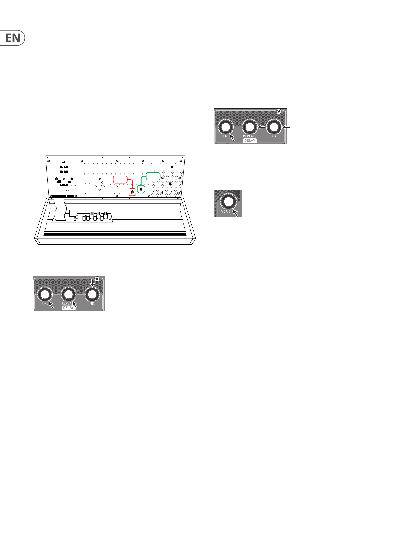
7. 3 Bucket Brigade Delay Calibration
The Neutron Delay stage is designed to give as much control and variety as
possible to the user. With that in mind, it may be necessary to tweak your
Neutron to sound the way you want it to.
First, decide how much feedback you want. Adding more feedback gives
the option of having the delay stage feedback on itself creating screaming
eects. This results in higher distortion through the circuit, which may be a
desirable eect.
Warning! When completing this procedure please keep the level down low as it
may get loud.
Open the Neutron by removing the top 8 screws. Lift the top panel carefully from
the lower edge to give access to trim pots VR37 and VR38. Take care not to put
strain on the ribbon connector.
1. Set the Delay Time and Repeats controls fully clockwise (turning to the right)
and set the Mix control to 12 o’clock.
2. Turn VR37 fully CW.
3. Turn the Time control fully counter clockwise to the left (faster repeats), the
circuit should feedback and scream at you.
4. With the delay feeding back on itself turn VR37 CCW until the repeats soften
but do not die o.
5. To test the setup:
- Turn the repeats fully CCW so that there are no repeats and the Time fully
clockwise for long repeats.
- Next, turn the repeats up full again.
- When the Time control is turned fully CCW the delay should start to
feedback again, if not dial VR37 CW a little further. Or alternatively, if it feeds
back too easily or if you don’t want this behavior at all, turn VR37 a little
more CCW to reduce the eect of the feedback.
If you would like clean repeats lower the amount of feedback so the delay does
not feedback on itself easily, or at all, and keep the level through the delay circuit
low. This can be achieved by using the Overdrive level to control the amount of
signal sent to the delay. This exibility lets you achieve clean and crisp repeats or
a delay that screams at you as you let it feedback on itself.
VR37
VR38
Clock Noise Calibration
Once the repeats calibration has been completed you may need to dial out some
clock noise from the delay output. This procedure has knock on eects to the
repeats calibration so once complete, you may need to repeat the previous stage
until you nd the right balance. The output level may need to be increased so
that clock noise can be heard; this will sound like a high frequency drone in the
background of any signals played through the delay.
1. Turn Time fully CW and both Repeats and Mix to 3 o’clock.
2. Set VCA Bias fully CW so a signal is fed through the system and heard at the
output. If you have no audio check that the VCF is not cutting o any audio
and that the Overdrive level is up. A low frequency sound may be best, one
so that you can easily distinguish the clock noise.
3. With a constant drone on the output turn VR38 until you can hear clock
noise, then move VR38 until the clock noise is at a minimum. Note, with long
repeats there will always be a bit of clock noise present.
21 NEUTRON User Manual
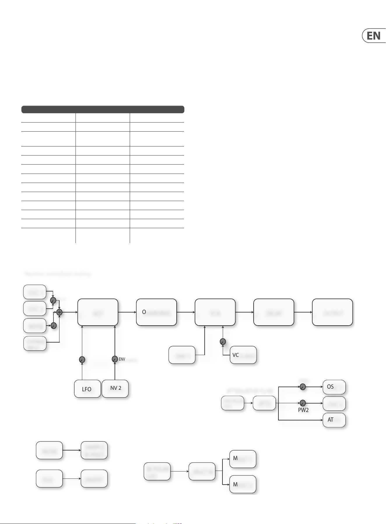
8. Patch Bay
In a patchable semi-modular synthesizer such as the Neutron, inputs and outputs
are independent from one another. It is up to the user to patch the modules
together as they wish. This is dierent from a normalized synthesizer where the
functions are hard-wired together and the user just changes parameters.
Patchable modular synthesizers are more complex to operate but give innite
options. Below is a table of default or normalized routings. Please refer to the
numbering diagram earlier in this document. There follows a block diagram of
the normalized signal ow to show how audio travels through the Neutron.
DEFAULT ROUTINGS
OUTPUT FROM GOES TO THEN INTO
OSC MIX + EXT INPUT +
NOISE
VCF>OD>VCA>DELAY LINE OUT + Headphones
ENV 1 VCA CV
LFO (BIPOLAR) ATT 2 ATT 1
ATTENUATOR 2 PULSE WIDTH 1&2
NOISE SAMPLE AND HOLD
LFO (BIPOLAR) FILTER DEPTH VCF FREQUENCY CV
ENV 2 ENV DEPTH VCF FREQUENCY CV
ASSIGN ATT1 CV
LFO (BIPOLAR) MULT INPUT
ENV 2 INVERT
E. GATE1 E. GATE2 UNLESS OVERRIDDEN
USING E. GATE 2 INPUT
ATTENUATOR FLOW
PW1
PW2
OSC 2
NOISE
OVERDRIVE
VCA DELAY
OSC 2
OUTPUT
LFO
ENV 2
ENV DEPTH
MOD DEPTH
OSC MIX
NOISE
SAMPLE
& HOLD
OSC 1
UNI-POLAR
LFO
ENV 1
ATT2
ATT1
VCF
EG2
INVERT
BI-POLAR
LFO
MULT IN
MULT 1
MULT 2
VCA BIAS
OSC 1
EXTRNAL
INPUT
Neutron normalised routing.
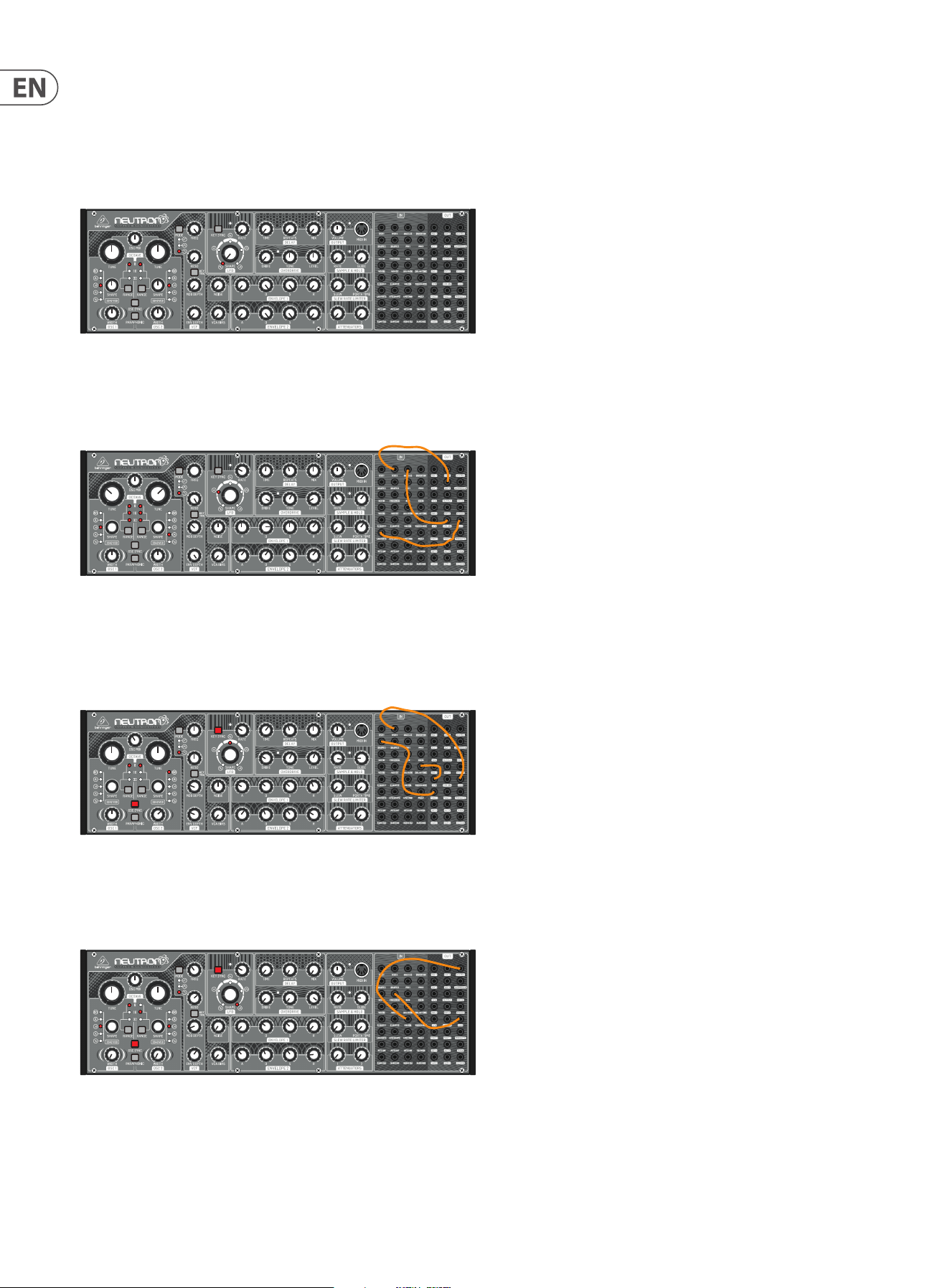
8.1 Tips and Tricks of the Patch Bay
1. Patch Sample and Hold out into FREQ MOD in. Turn MOD DEPTH to 12 o’clock.
Then Turn the S&H rate to 3 o’clock and the GLIDE to 12 0’clock. This will give you
a random lter position which glides between lter cuto points.
2. Patch LFO to PW1 and MULT 1 into INVERT IN, then INVERT OUT to PW2 for
opposite direction pulse width modulation. This is a is a variation that sounds
slightly dierent to turning ATTENUATOR 2 (see normalized routings for details).
3. With OSC 1&2 in blend mode, patch LFO to SHAPE 1. Patch MULT 1 into INVERT
IN then INVERT OUT into Shape 2 for opposite direction oscillator shape shifting, a
very powerful sound creation tool.
4. Set both OSC to Tone Mod Shape and ENV 2 to PW1&2 via the Mult with slow
ADSR settings. This gives a rich Pulse Width Modulation (PWM) eect.
5. Patch LFO into ATT 1 IN, then patch ATT1 OUT to DELAY TIME IN. Set a short
delay with the delay mix around 50% and adjust the LFO speed and shape to
create a chorus eect.
6. Patch VCF 1&2 into Sum 1 A&B. Patch the output of SUM 1 into OD In. Set the
lter shape to LPF to create a notch lter.
7. Patch a square wave shape LFO out to the delay time in. Then try ENV2 out
patched to LFO Rate. This sounds like and 80’s computer game.
8. Patch OSC 1 into OSC 2 with OSC SYNC active for frequency
modulation synthesis.
9. Patch LFO into ATT 1 IN, Then ATT 1 into OSC2 with OSC SYNC active. This gives
another style of FM synthesis to experiment with while using both oscillators. Try
changing the position of ATT 1 to hear subtle changes.
10. Patch ASSIGN to ATT1 CV, set ASSIGN to MOD WHEEL, patch ATT1 OUT into OSC
1&2 pitch CV, this way the mod wheel sets the depth of vibrato, with LFO rate/
shape setting the characteristics and ATT2 setting the maximum depth.
22 NEUTRON User Manual
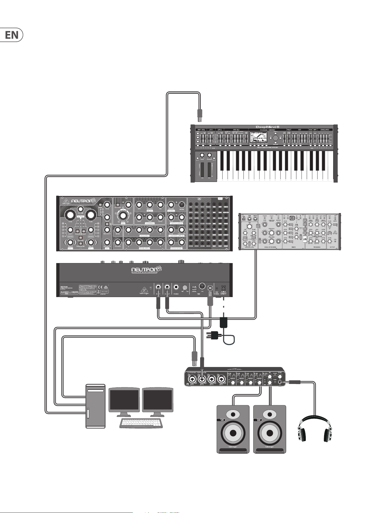
9. Neutron Set-up Examples
Studio System
Desktop Computer
MIDI KEYBOARD USB B
(MIDI OUTPUT OVER USB)
Headphones
Studio Monitors
Audio Interface
USB B
Audio Input Audio Output
MIDI Input
Over USB
MIDI Input
Over USB
USB A
Power
Adaptor
Audio Output
(to be proccessed by Neutron)
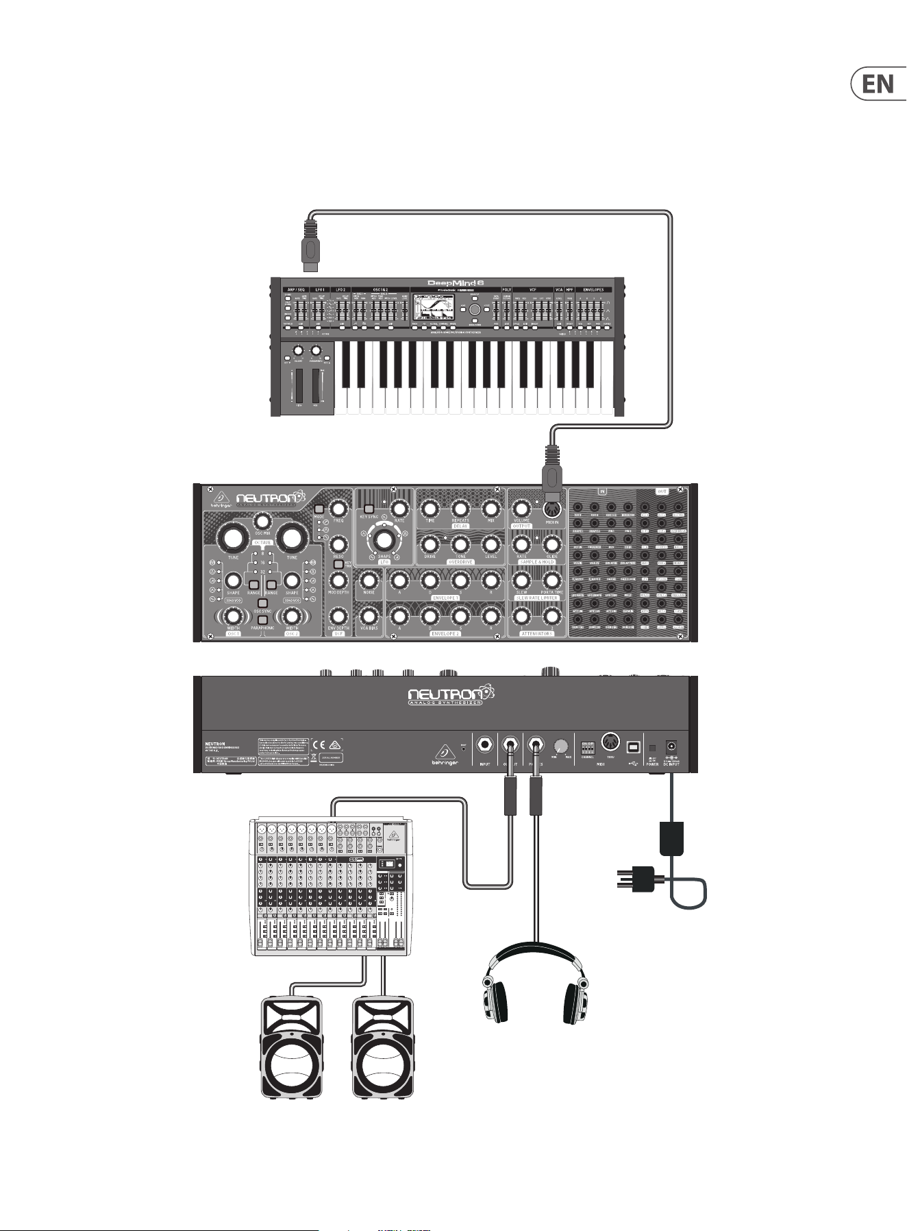
23 NEUTRON User Manual
Live Set-up
Power
Adaptor
MIDI KEYBOARD
MIDI OUTPUT
Headphones
MIDI Keyboard
MIDI OUT
Mixing console
Active Loudspeakers
MIDI IN
24 NEUTRON User Manual
11. Troubleshooting
Before turning on the Neutron power, please check that:
Your speakers or headphones are correctly connected.
The external devices are powered-o.
Turn the VOLUME knob on the Neutron to the o position.
Turn on the POWER switch located on the rear panel.
The Neutron will run its startup routine.
Once the Neutron has stopped the LED calibration sequence, you can then turn on
power to the connected devices and raise the volume to an appropriate level.
Before turning o the Neutron, please check that:
The output level is down on all connected audio devices.
The power is then turned o for all connected audio devices.
11.1 There is no sound coming from the
synthesizer.
Check if the audio connections are correct.
Check if the volume control is turned up.
Check if the overdrive volume is up as this can cut audio if fully turned to the left.
If using headphones, check that the volume on the rear of the Neutron is
turned up.
Check the position of the FREQ cuto point. Depending on the lter type selected,
it determines where the FREQ control will let audio pass through the lter stage.
Check that any patch cables that are in use are not cutting the sound.
For example, if a 3.5 mm cable is patched into VCA IN and the other end of the
cable is not plugged in, no sound will be audible.
11. 2 There is no mIDI data coming from an
external source.
Check if the MIDI connections are made to the USB or the MIDI IN on the
front panel.
Check if the Neutron MIDI channel is set to the same one as the transmitting
device using the DIP switches on the rear.
Check that you are using either USB or MIDI. The Neutron may not respond if two
sets of MIDI data are being transmitted to it via USB and the MIDI IN port at the
same time.
11. 3 The synthesizer is behaving erratically.
Check that any connected devices/applications are not creating a MIDI loop which
is feeding back MIDI data.
11.4 The synthesizer sounds out of tune.
The Neutron calibrates its tuning on start up. If it sounds out of tune, please look
at section 5.4 to tune the oscillators to your choice of MIDI note.
10. Preset Patches
The following examples give you a glimpse into the wonderful world of modular
synthesis. Try these patches to show the versatile power of the Neutron.
Default Patch - This is a great starting point for sound creation. No patching
required. A standard sawtooth sound will be audible using these settings.
Out Of This World – A Sci- style sound showing o the S&H function of the
Neutron. Here, the VCF self-resonates and drops into wonderfully deep sub tones.
Play with the VCF FREQ control to sweep through various textures. Patch VCF 2
into OSC 2, LFO UNI into OSC 1&2 and S&H into LFO RATE.
Edge Synth – A slow evolving sound using frequency modulation and wave
shape blending to create either a screaming when the lter is set to HPF or a dark
bubbling bass with the lter set to LPF.
Patch S&H OUT to OSC 2 IN, LFO to DELAY TIME and MULT 1 (LFO BY DEFAULT) to
SHAPE 1.
Quantum Loop - A Sub Sawtooth sound with VCF squelch. A sample & hold noise
loop is added to give some movement to the sound. Try dierent amounts of
resonance to hear the variations.
Patch OSC MIX to S&H IN then S&H OUT to FREQ MOD.
25 NEUTRON User Manual
11. 5 Buzzing or humming sounds can be heard
from the audio outputs.
USB and or audio connections made between dierent devices using dierent
power supplies, sources or sockets can sometimes create ground loops. You can
attempt to resolve these grounding issues between computers and the Neutron
by following good grounding practice and ensuring all devices use the same
ground point. Unplugging one cable at time can make the background noises
better or worse, depending on how this aects the remaining ground loops.
By removing every audio cable and working through your studio item by item,
you can potentially eradicate ground-loop problems. Other possible solutions
include the use of a DI box to connect the Neutron to your audio mixer or sound
card where the transformer will isolate the audio connections.
11.6 There is no sound when using the external
audio input.
The Neutron needs the VCA envelope to be triggered and open. This can be
achieved via MIDI or an external E.GATE 1 input, adjust the ADSR settings in order
to hear the input signal.
Another way to use the external audio input is turning up the VCA BIAS in order
to hear audio.
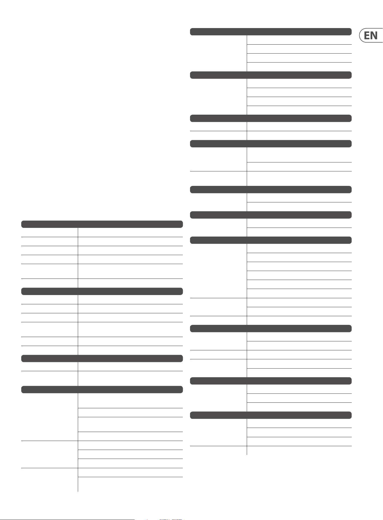
12. Specications
Synthesizer Architecture
Number of oscillators 2 x V3340
Type Analog
Oscillators 2 (0.7 Hz to 55 kHz across 4 ranges)
LFO 1 (0.01 Hz to 10 kHz)
VCF
1 (switchable low pass, band pass or high pass
(12 dB/octave slope), dual output
Envelopes 2 analog envelope generators
Connectivity
External input ¼" TS, unbalanced, 100 kΩ impedance
Output ¼" TRS, balanced, max. 12dBu
Headphones ¼" TRS, balanced
Headphones output
impedance
8 Ω
MIDI In/Out (soft Thru) 5-pin DIN/ 16 channels
USB (MIDI) USB 2.0, type B
USB
Type Class compliant USB 2.0, type B
Supported operating
systems
Windows 7 or higher/ Mac OS X 10.6.8 or higher
Oscillator Section
Controls
Tune (OSC 1&2): +1/-1 octave (8', 16' or 32') or +10/-10
(full range)
OSC mix: (linear blend control between OSC 1&2)
Shape (OSC 1&2): Tone Mod, Square, Sawtooth, Triangular
or Sine
Pulse width: 0 to 100% (OSC 1&2)
Switches
Range (OSC 1&2): 8', 16' or 32' or full range (all 3 LEDs)
OSC sync: on/o
Paraphonic: on/o
LED
Octave (OSC 1&2) 8', 16' or 32' or +/-10 (all 3 LEDs)
Shape (OSC 1&2): Tone Mod, Square, Sawtooth, Triangular
or Sine
Envelope 1
Controls
Attack: 300 µs to 5 s (linear attack)
Decay: 2.4 ms to 10 s (exponential decay)
Sustain: 0 V to 9 V
Release: 1.5 ms to 6 s (exponential release)
Envelope 2
Controls
Attack: 300 µs to 5 s (linear attack)
Decay: 2.4 ms to 10 s (exponential decay)
Sustain: 0 V to 9 V
Release: 1.5 ms to 6 s (exponential release)
Output Section
Controls Volume: 0 to 100%
LED MIDI: Gate signal
Sample & Hold Section
Controls
Rate: 0.26 Hz to 28 Hz (can be clocked from extrenal
source)
Glide: 500 µs to 1 s
LED Rate: 0.26 Hz to 28 Hz (can be clocked from extrenal
source)
Slew Rate Limiter Section
Controls
Slew rate: 1 ms to 3 s
Portamento time: 0 to 10 s
Attenuator Section
Controls
Attenuator 1: +4 dB to -∞
Attenuator 2: 0 dB to -∞
Filter Section
Controls
Cuto frequency: 10 Hz to 15 kHz
Resonance: 0 to 10 (capable of self oscillation)
Modualtion depth: 0 to 100%
Envelope depth: 0 to 100%
Noise: 0 to 100%
VCA bias: 0 to 100%
Switches
Filter mode, high pass, band pass and low pass
Filter key track: on/o
LED Filter mode, high pass, band pass and low pass
LFO Section
Controls
Shape: Sine, Triangle, Sawtooth, Square and Ramp
Rate: 0 to 10 (0.01Hz to 10kHz)
Switches Key sync: on/o
LED
Rate/Level indicator
Shape: Sine, Triangle, Sawtooth, Square and Ramp.
Delay Section
Controls
Time: 25 ms to 640 ms
Repeats: 0 to 100%
Mix: 0 to 100%
Overdrive Section
Controls
Drive: 0 to 11
Tone: 0 to 10
Level: 0 dB to -∞
LED Drive amount indicator
26 NEUTRON User Manual
Inputs (TS 3.5 mm)
OSC 1 Control voltage: 1 V per octave
OSC 2 Control voltage: 1 V per octave
OSC 1&2 Control voltage: 1 V per octave
INVERT IN inverts voltage
SHAPE 1 Control voltage: -5 V to +5 V
SHAPE 2 Control voltage: -5 V to +5 V
PULSE WIDTH 1 Control voltage: -5 V to +5 V
PULSE WIDTH 2 Control voltage: -5 V to +5 V
VCF IN Signal input
FREQ MOD Control voltage: -5 V to +5 V
RESONANCE Control voltage: -5 V to +5 V
OVERDRIVE IN Signal input
VCA IN Signal input
VCA CV Control voltage: -9 V to +9 V
DELAY IN Signal input
DELAY TIME Control voltage: -5 V to +5 V
E GATE 1 Control voltage: -5 V to +5 V (envelope triggers @ 1.5 V)
E GATE 2 Control voltage: -5 V to +5 V (envelope triggers @ 1.5 V)
SAMPLE & HOLD IN Signal input
SAMPLE & HOLD CLOCK Control voltage: -5 V to +5 V (S&H triggers @ 3 V)
LFO RATE Control voltage: -5 V to +5 V
LFO SHAPE Control voltage: -5 V to +5 V
LFO TRIG Control voltage: -5 V to +5 V (S&H triggers @ 1.6 V)
MULT (Multiple) Input Signal is duplicated on Mult 1 and Mult 2 outputs
ATT 1 IN Signal input
ATT 1 CV Control voltage: -5 V to +5 V
ATT 2 IN Signal input
SLEW IN Signal or CV input
SUM1(A) Signal input or CV input
SUM1(B) Signal input or CV input
SUM2(A) Signal input or CV input
SUM2(B) Signal input or CV input
Outputs (TS 3.5 mm)
OSC 1 Max. +14 dBu
OSC 2 Max. +14 dBu
OSC Mix Max. +14 dBu
VCF 1 Max. +12 dBu
VCF 2 Max. +12 dBu
OVERDRIVE Max. +18 dBu
VCA Max. +18 dBu
OUTPUT Max. +15 dBu
NOISE Max. +18 dBu
ENV 1 Control voltage: 0 V to +9 V
ENV 2 Control voltage: 0 V to +9 V
INVERT inverts signals up to +/-9.5 V
LFO Control voltage: -5 V to +5 V
LFO UNI Control voltage: 0 V to +5 V
SAMPLE & HOLD Tracks input voltage upto a maxiumum of 9.5 V
MULT 1 Tracks input voltage upto a maxiumum of 9.5 V
MULT 2 Tracks input voltage upto a maxiumum of 9.5 V
MIDI GATE Control voltage: 0 V to +3.3 V
ATT 1 Control voltage -9.5 V to +9.5 V (dependant on input
signal)
ATT 2 Max output voltage dependant on input signal
SLEW Control Voltage -9.5 V to +9.5 V (dependant on input
signal)
SUM 1 Control Voltage -9.5 V to +9.5 V (dependant on input
signals)
SUM 2 Control Voltage -9.5 V to +9.5 V (dependant on input
signals)
ASSIGN Control voltage: 0 V to +5 V
Power Requirements
External power adaptor 12 V DC, 1000 mA (12 W)
Power consumption 7.5-9 W typical
Enviormental
Operating temperature
range
5 °C to 40 °C (41 °F to 104 °F)
Physical
Dimensions (H x W x D) 94 x 424 x 136 mm (3.7 x 16.7 x 5.4")
Weight 2.0 kg (4.4 lbs)
Shipping weight 3.0 kg (6.6 lbs)
Eurorack HP 80 HP
27 NEUTRON User Manual
13. Appendix A
mIDI Control Change (CC) functions
There are 2 MIDI CC functions that the Neutron supports:
• Modulation wheel or lever- MIDI CC 0x01 (MSB) & MIDI CC 0x21 (LSB).
This is routed to the assign out when selected as the assign out option
• Damper Pedal on/o (Sustain)- MIDI CC 0x40.
System Exclusive Commands
Various parameters in the Neutron synthesizer can be changed using MIDI system
exclusive (SysEx) commands. A MIDI utility such as the popular MIDI OX can be
used to send the SysEx command data string to the Neutron by using the USB
MIDI connection between a host computer and the Neutron.
Section 7.2 shows a typical procedure for sending a SysEx message to the
Neutron, and it can be used to send any of the following SysEx messages.
Below is a table of SysEx commands.
This table lists the SysEx commands supported by the Neutron.
Note that the general format of a Neutron SysEx message is:
*note: the device ID is not the same as MIDI channel. The valid range is
0-15 (default 0) or 7F (multicast to all Neutrons)
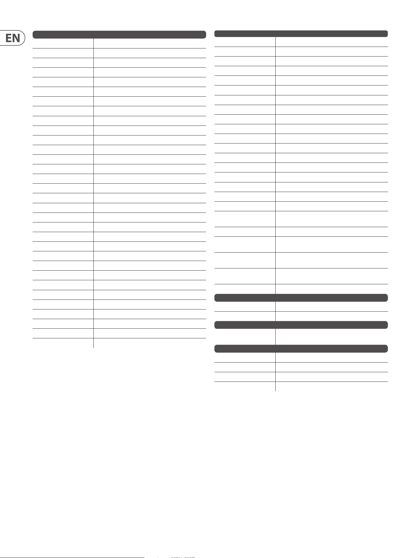
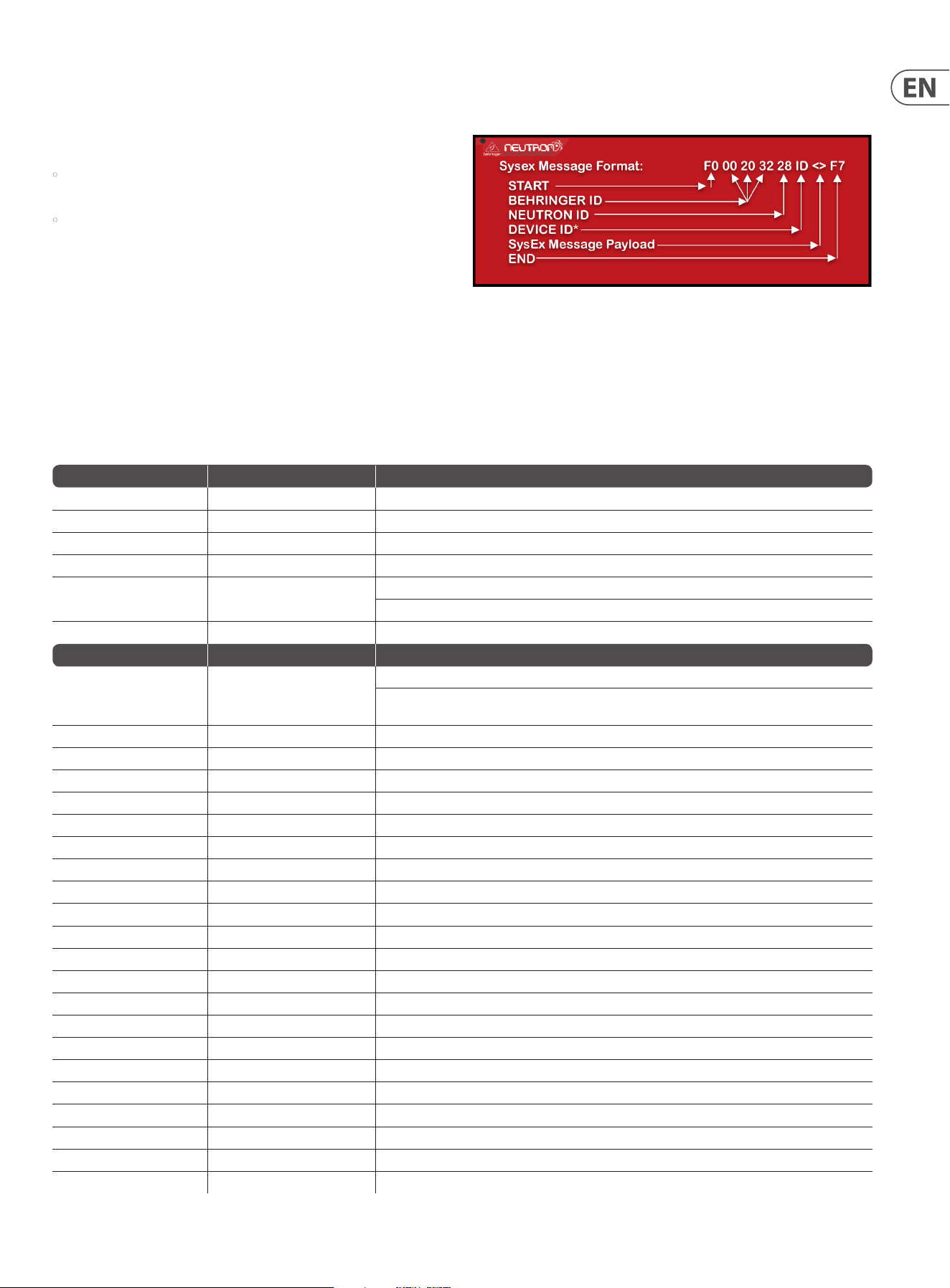
Sysex
SysEx Command Sysex Notes
Set Global Setting F0 00 20 32 28 ID 0A <> F7 See "Global Setting Command" table below
Restore Global Settings F0 00 20 32 28 ID 0B F7 Restores defaults - does not erase calibration data
Calibration mode command F0 00 20 32 28 ID 10 <> F7 See "Calibration Command" table below
Software Version request F0 00 20 32 28 ID 73 F7 No notes
Software Version response F0 00 20 32 28 ID 74 MM NN F7 MM - Comms protocol version
NN - variable length ASCII string detailing the software version
Global Setting Update F0 00 20 32 28 ID 5A MM <> F7 MM - Comms protocol version
Global Setting Command Sysex Notes
Set MIDI channel (*) F0 00 20 32 28 ID 0A 00 MM F7 MM = 0-F --> MIDI channel 1-16
Note: using this command to set the MIDI channel will automatically disable the DIP switches on the back panel
(which will persist across power cycles)
Set Key Priority F0 00 20 32 28 ID 0A 01 MM F7 MM = 0-LO, 1-HI, 2-Last. Default:2-Last
Set Pitch Bend Range (*) F0 00 20 32 28 ID 0A 03 MM F7 MM = 0-24 (semitones). Default:2
Set ASSIGN out F0 00 20 32 28 ID 0A 04 MM F7 MM = 0-OSC 1 CV, 1-OSC 2 CV, 2-"Note On" velocity, 3-Modwheel, 4-Aftertouch. Default:0
Set Envelope retriggering F0 00 20 32 28 ID 0A 05 MM F7 MM = 1-Enabled, 0-Disabled. Default:0-Disabled
Reset Min/Max MIDI notes F0 00 20 32 28 ID 0A 06 MM F7 MM = not used
Set Polychain Mode F0 00 20 32 28 ID 0A 08 MM F7 MM = 0-Disabled, 1-Enabled. Default:0
Set Device ID F0 00 20 32 28 ID 0A 09 MM F7 MM = 0-F --> MIDI ID 1-16. Default:0
Disable MIDI DIP switches F0 00 20 32 28 ID 0A 0A MM F7 MM = 0-Enabled, 1-Disabled. Default:0-Enabled
Set Mute Out-Of-Range notes F0 00 20 32 28 ID 0A 0B MM F7 MM = 1-nute, 0-not mute. Default:0-not mute
SetMin MIDI note F0 00 20 32 28 ID 0A 0C MM F7 MM = MIDI note number. Default:24
Set Max MIDI note F0 00 20 32 28 ID 0A 0D MM F7 MM = MIDI note number. Default:96
Set OSC Sync F0 00 20 32 28 ID 0A 0E MM F7 MM = 0-Enabled, 1-Disabled. Default:0-Enabled
Set Paraphonic Mode F0 00 20 32 28 ID 0A 0F MM F7 MM = 0-Monophonic, 1-Paraphonic. Default:0-Monophonic
Set VCF mode F0 00 20 32 28 ID 0A 10 MM F7 MM = 0-HP,1-BP,2-LP
Set VCF keytrack F0 00 20 32 28 ID 0A 11 MM F7 MM = 0-Disabled, 1-Enabled. Default:0
Set VCF mod src F0 00 20 32 28 ID 0A 12 MM F7 MM = 0-Disabled, 1-aftertouch, 2-modwheel, 3-velocity
SetVCF mod depth F0 00 20 32 28 ID 0A 14 MM F7 MM = 0-3F where 0 is the minimum & 3F(63dec) is the maximum (100%)
Set OSC 1 shape blend F0 00 20 32 28 ID 0A 20 MM F7 MM = 1-No blend, 0-Blend. Default:0-Blend
Set OSC 2 shape blend F0 00 20 32 28 ID 0A 21 MM F7 MM = 1-No blend, 0-Blend. Default:0-Blend
Set OSC 1 tune pot bypass F0 00 20 32 28 ID 0A 22 MM F7 MM = 0-Not bypassed, 1-Bypassed. Default:0-Not bypassed
Set OSC 2 tune pot bypass F0 00 20 32 28 ID 0A 23 MM F7 MM = 0-Not bypassed, 1-Bypassed. Default:0-Not bypassed
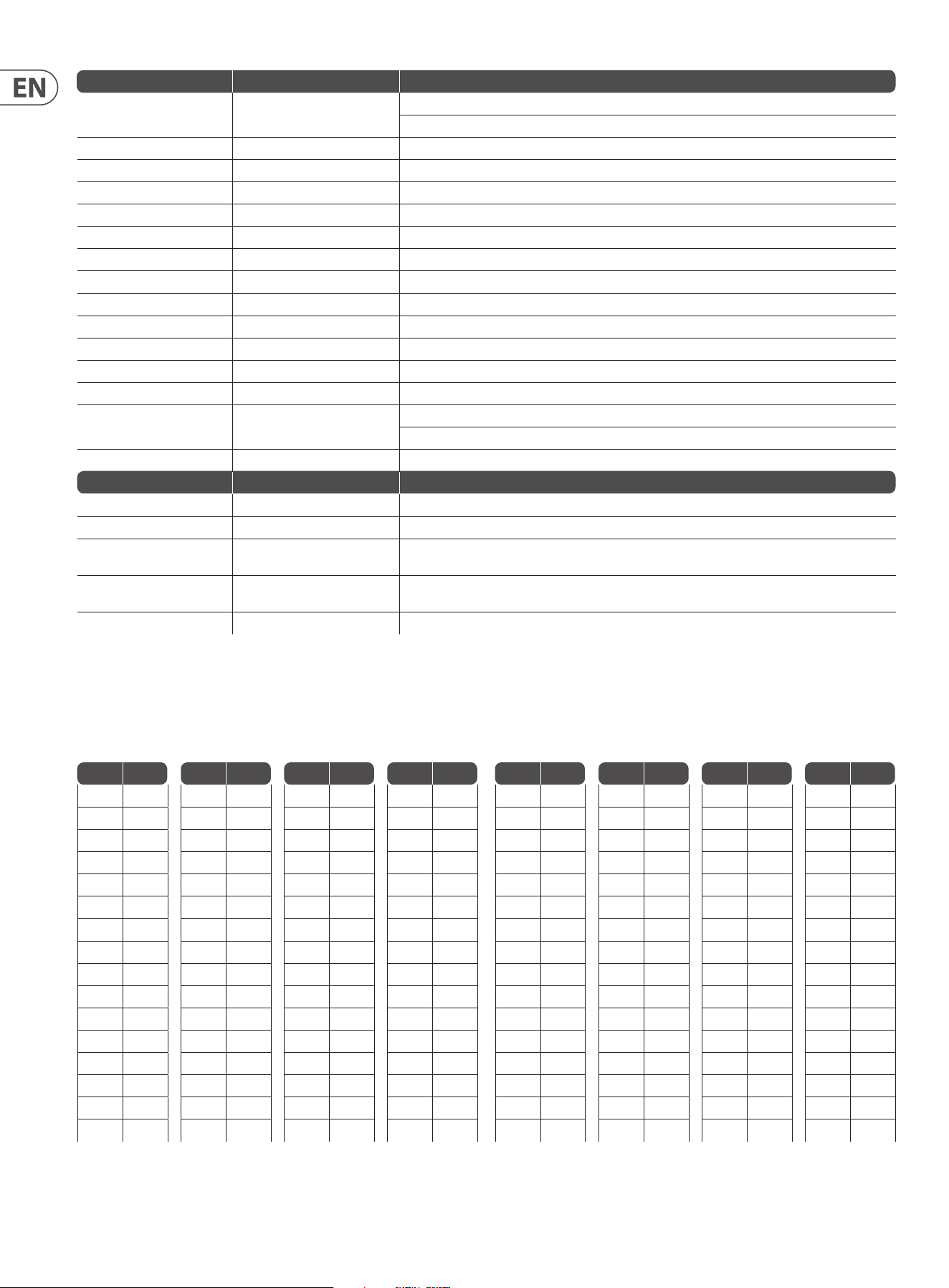
28 NEUTRON User Manual
Global Setting Command Sysex Notes
Set OSC 1 autoglide F0 00 20 32 28 ID 0A 24 MM F7 MM = 0-24 Range is -12->+12 so 12 is no autoglide.
Default:12-No autoglide
Set OSC 2 autoglide F0 00 20 32 28 ID 0A 25 MM F7 Default:12-No autoglide
Set OSC 1 range F0 00 20 32 28 ID 0A 26 MM F7 MM = 0[32'], 1[16'], 2[8'] & 3[+/- 10 oct mode]
Set OSC 2 range F0 00 20 32 28 ID 0A 27 MM F7 MM = 0[32'], 1[16'], 2[8'] & 3[+/- 10 oct mode]
Set OSC key split (*) F0 00 20 32 28 ID 0A 28 MM F7 MM = 0, 24-88. Key split note#, 0-o. Default:0-o. NB key split note# is the start of OSC2 range
Set LFO shape blend F0 00 20 32 28 ID 0A 30 MM F7 MM = 1-No blend, 0-Blend. Default:0-Blend
Set LFO One shot mode F0 00 20 32 28 ID 0A 31 MM F7 MM = 1-Enabled, 0-Disabled. Default:0-Disabled
Set LFO rate key track key (*) F0 00 20 32 28 ID 0A 32 MM F7 MM = LFO rate root MIDI note number 12-108. 0 – Disabled
Set LFO depth F0 00 20 32 28 ID 0A 34 MM F7 MM = 0-20%, 1-40%, 2-60%, 3-80%, 4-100%. Default:4-100%
Set LFO ignore MIDI CLK sync F0 00 20 32 28 ID 0A 35 MM F7 MM = 0-CLK sync, 1-ignore CLK sync. Default:0-CLK sync
Set LFO key sync F0 00 20 32 28 ID 0A 37 MM F7 MM = 0-Enabled, 1-Disabled. Default:0-Enabled
Set LFO Shape order (2) F0 00 20 32 28 ID 0A 38 MM F7 MM = LFO Slot index: =0..4 NN = LFO shape value: = 0..4
Restore LFO Shape order F0 00 20 32 28 ID 0A 39 MM F7 MM - Not used
Set LFO Shape phase F0 00 20 32 28 ID 0A 3A MM NN F7 MM = LFO Shape index: =0..4
NN = LFO phase value: = 0..7 - in eighths of 2*PI (or 45 degrees)
Set LFO retrigger F0 00 20 32 28 ID 0A 3B MM F7 MM = 0-overlapping notes will not retrigger the LFO, 1-overlapping notes will retrigger the LFO.
Calibration Command Sysex Notes
ASSIGN out calibration 1V F0 00 20 32 28 ID 10 20 F7 Enter calibration mode 1V
ASSIGN out calibration 4V F0 00 20 32 28 ID 10 21 F7 Enter calibration mode 4V
ASSIGN out calibration +V F0 00 20 32 28 ID 10 23 <N> F7 Increase voltage. <N> is an optional value (2-7F) which will increase the step voltage change linearly.
If omitted a value of 1 is used
ASSIGN out calibration -V F0 00 20 32 28 ID 10 22 <N> F7 Decrease voltage. <N> is an optional value (2-7F) which will increase the step voltage change linearly.
If omitted a value of 1 is used
ASSIGN out save & exit F0 00 20 32 28 ID 10 24 F7 Stores calibration data & exits
Decimal to Hex Table
The SysEx Message Payload works in Hex format. Use the Decimal to Hex Table to nd the Hex value you require. All SysEx messages in the above table that have a (*)
will require you to turn the Midi note number into a hex number using the table below.
Dec Hex
0 0
1 1
2 2
3 3
4 4
5 5
6 6
7 7
8 8
9 9
10 A
11 B
12 C
13 D
14 E
15 F
Dec Hex
16 10
17 11
18 12
19 13
20 14
21 15
22 16
23 17
24 18
25 19
26 1A
27 1B
28 1C
29 1D
30 1E
31 1F
Dec Hex
32 20
33 21
34 22
35 23
36 24
37 25
38 26
39 27
40 28
41 29
42 2A
43 2B
44 2C
45 2D
46 2E
47 2F
Dec Hex
48 30
49 31
50 32
51 33
52 34
53 35
54 36
55 37
56 38
57 39
58 3A
59 3B
60 3C
61 3D
62 3E
63 3F
Dec Hex
64 40
65 41
66 42
67 43
68 44
69 45
70 46
71 47
72 48
73 49
74 4A
75 4B
76 4C
77 4D
78 4E
79 4F
Dec Hex
80 50
81 51
82 52
83 53
84 54
85 55
86 56
87 57
88 58
89 59
90 5A
91 5B
92 5C
93 5D
94 5E
95 5F
Dec Hex
96 60
97 61
98 62
99 63
100 64
101 65
102 66
103 67
104 68
105 69
106 6A
107 6B
108 6C
109 6D
110 6E
111 6F
Dec Hex
112 70
113 71
114 72
115 73
116 74
117 75
118 76
119 77
120 78
121 79
122 7A
123 7B
124 7C
125 7D
126 7E
127 7F
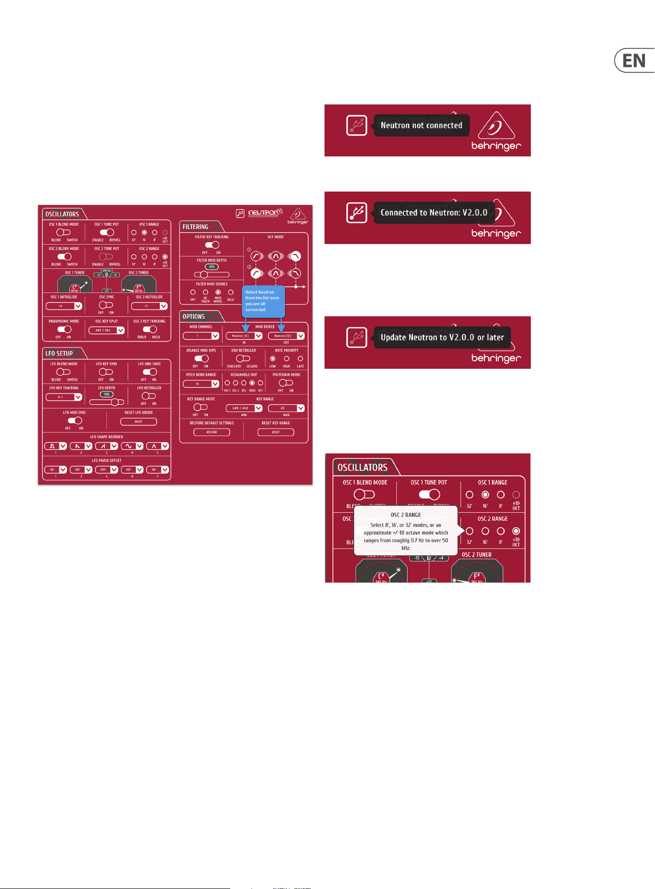
29 NEUTRON User Manual
15. Appendix B Neutron App
The Neutron app is designed to control the Neutron’s complex features in an easy
to use format.
To use the app, simply download the latest version from the
www.musictribe.com website and follow the installation instructions.
Any Neutron will need to be updated to version V2.0.0 or higher in order for
the Neutron to be recognised in the App.
Once your Mac or PC is connected via USB, open the app, set-up and enjoy easy
control of many parameters of the Neutron Synthesizer as described earlier in
this manual.
To use the Neutron app:
1. Connect USB out of your computer to the Neutron USB input.
2. Power your Neutron and Computer on.
3. Open the Neutron app.
4. Select ‘Neutron’ in the MIDI device list for IN and OUT. It is possible to have
multiple Neutrons connected with the same device ID. The input and output
will be in corresponding positions in the list if you have multiple devices and
have not change the device ID via SysEx.
5. The app will populate with now show the current settings of the
connected Neutron.
The USB icon in the top right of the App has 3 states, clicking on the icon reveals
more detail.
1 - No connection grey out USB.
2 - Successful connection. Click for software version.
3 – Continual double blink will be displayed for out dated rmware and shows
the connected Neutron needs updating. Note this function will only work
currently with a Neutron using rmware V2.0.0 or higher. If you are using an
older rmware, the message will display as "Neutron not connected".
Help information
Right clicking over a function in the Neutron app software will give you a
description of the function.

30 NEUTRON User Manual
16. Glossary
NEUTrON GLOSSAry
This glossary provides an explanation of useful symbols, terms and abbreviations.
32'/16'/8': Used to describe the range of an oscillator, this term originates from
pipe organs. for example, an 8' pipe is one octave higher than an 16' pipe.
ADSR: Attack, Decay, Sustain and Release, an envelope with four stages.
Aftertouch: Aftertouchis MIDI data sent when pressure is applied to a keyboard
after the key has been struck, and while it is being held down or sustained.
Attack Time: The rst stage of an ADSR envelope, used to control the initial
part of a sound. Specied as the duration of time for an envelope to reach the
maximum level after it has been triggered on by a key press or gate signal.
Attenuate: To reduce the level of a signal.
Autoglide: Played as a smooth and linear increase or decrease in pitch rather
than a semitone step-change. The number of semitones that the start of the note
'glides through' for the selected note can be changed and be + or -.
Band Pass Filter (BPF): A lter that passes frequencies within a certain range
and rejects (attenuates) frequencies outside that range.
Bipolar: a signal that includes positive and negative values.
Cent: Unit of measurement for pitch tuning. There are one hundred cents
in a semitone.
Control Voltage (CV): A voltage signal used to control a parameter. Was
common on synthesizers before MIDI and is now found mostly on modular
synthesizers.
Cut-O Frequency: The frequency which the lter is set to. Beyond this
frequency the sound is cut depending on the type of lter used. See LPF,
BPF and HPF.
dBu: A unit of measurement of sound used in professional audio.
DC Oset: A DC voltage which is added to an AC waveform.
Decay Time: The second stage of an ADSR envelope. Specied as the duration of
time for an envelope to reach the sustain level after the maximum level has been
reached during the attack stage.
Digital Audio Workstation (DAW): A computer-based recording system.
More commonly used to describe the software package used to record,
process and mix.
Distortion: An eect which adds harmonic content to a signal.
Drive: Provide a gain boost to produce soft clipping.
Eect: One of a number of audio processes that can be applied to a signal to
modify it, such as reverb, anging, phasing, delay etc.
Envelope Generator (EG): An envelope signal which can be adjusted to a
specic shape in order to control the way a sound behaves over time.
Feedback: A loop created between an audio input and an audio output of an
audio circuit, system or processing block.
Filter: A device that attenuates certain frequencies while letting other
frequencies through. Using a lter to reduce harmonics, changes the timbre or
color of the sound.
Frequency Modulation (FM): Using one frequency to modulate another
frequency's pitch. When the modulation source is in the audio range, it can be
perceived as a change in the timbre or color of the sound. FM can be used to
create a wide range of rich and complex sounds and is often described as having
a clear and distinctive timbre.
Frequency: Measured in Hz.
Gain: The amount of signal level increase provided by an amplier stage.
Gate (Synthesizer): A signal used to trigger an event, such as a note or
an envelope.
Harmonics: A series of integer-related sine waves at varying levels creating
dierent timbres. Waveforms (other than a pure sinusoidal) generate various
harmonics which help dene the character of the sound.
High Pass Filter (LPF): A lter that attenuates lower frequencies below the
lter cuto point, leaving the higher frequencies unaected.
Invert: To change it to its opposite, e.g. change a positive value becomes
negative etc.
Keyboard Tracking: Allows the control signal from received midi notes to
adjust another parameter. The Neutron uses keyboard tracking to move the lter
cut o frequency relative to the played note.
Kilohertz (kHz): A unit of frequency equal to one thousand cycles of a wave
per second.
Level: Used to describe the magnitude of a sound, often relative to an
arbitrary reference.
Line Level: A nominal operating level used by audio equipment.
Low Frequency Oscillator (LFO): An oscillator that commonly runs at a very
low speed and is used to modulate another parameter.
MIDI (Musical Instrument Digital Interface): A technical standard that
describes a protocol, digital interface and connectors and allows a wide variety of
electronic musical instruments, computers and other related hardware/software
devices to connect and communicate.
MIDI Clock: A clock signal which is broadcast over MIDI to ensure that devices are
synchronized. Also known as MIDI Beat Clock or MIDI Timing Clock.
MIDI Message: Data or information transmitted from one MIDI device
to another.
MIDI Gate: The MIDI Gate typically controls the note on-o.
Mix: The balance of level between one signal and another.
Modulation: The process of controlling one or more properties (destinations) of
a signal using another signal (source).
Modulation Wheel (Mod Wheel): A wheel located to the left of a keyboard
that allows you to change specied parameters in real-time.
Monitors: Studio quality loudspeakers, providing an accurate representation of
the audio signals.
Mono: Signal channel audio.
Monophonic: Only one note can be played at any given time, as there is only a
single voice.
Mute: Function that allows a signal to be silenced.
N/A: An electronic device which generates a periodic signal .
Noise: A circuit that produces white noise.
Note-Priority: Determines which note is played when more notes are held
simultaneously than the number of available voices (often: low/high/last).
Octave or Oct: Unit of measurement for pitch. Every time the frequency of a
waveform doubles, the pitch increases by one octave.
Oscillator: An electronic device which generates a periodic signal used to form
the basis of a synthesizer program.
Output: The signal sent out by a device or process. Also used to describe the
physical socket where a signal leaves a device.

31 NEUTRON User Manual
Overdrive: Topush toexcess or drive too hard.
Parameter: A setting whose value can be changed.
Parametric EQ: A type of EQ that allows all of the parameters of equalization to
be changed, including center frequency, boost/cut in gain and bandwidth.
Paraphonic: Is the use of two oscillators independently pitched when more than
one MIDI note is played.
Patch: The cables used on modular synthesizers (or synthesizers with modular
compatibility) to connect devices together. Patch cables can carry audio, gate or
control voltage signals.
Phase: A measurement (in degrees) of the time dierence between two
waveforms, or between a single waveform and a reference point.
Pitch Bend / Pitch Bend Wheel: Controlling the pitch of a note after it has
been played.
Polyphonic: Capable of playing more than one note at once.
Polyphony: The number of notes a polyphonic synthesizer can
play simultaneously.
Portamento: An adjustable performance eect that glides or bends the pitch
from one note to the next.
Poly-Chaining: A way to connect multiple monophonic synths to play together
to create a polyphonic sound.
Power Supply Unit (PSU): The component in a system which is responsible for
supplying and managing power.
Psychoacoustics: The study of the perception of sound, that is, how we
listen, our psychological responses, and the physiological eects on the human
nervous system.
Pulse Wave: Similar to a square wave, but without symmetry. Also known as a
"Rectangle Wave."
Pulse Width Modulation (PWM): Modulation of the pulse width (the duty
cycle of a pulse wave measured as a percentage). A pulse width of 50% has equal
positive and negative sections and is considered a square wave.
Rate: The speed at which a particular device is operating.
Release Time: The fourth and nal stage of an ADSR envelope. Specied as the
duration of time for an envelope to reach zero after the played key is released.
Resonance (Reso): The emphasis/boost of frequencies around the
cut-o frequency.
Reverb: An eect where the ambience of a physical space is simulated.
s: Symbol for "second," a unit of time.
Sample & Hold (S&H): A circuit or function in synthesizersthat enables the
instantaneous value (voltage) of a waveform to be captured and continues to
output that value until the nextsampleis taken.
Sawtooth: A waveform that combines an instantaneous rise or fall, followed
by a gradual linear incline or decline. The name comes from the waveform's
similarity to the teeth of a saw.
Semitone: A chromatic half-step. There are twelve semitones in an octave.
Self-oscillation: Occurs when the resonance of a lter is increased to the point
where it will begin to generate a sine wave independently of any input.
Signal ow: The path of a signal from one module (or component of a system)
to another.
Sinusoidal / Sine Wave: Mathematical description of a smooth waveform that
contains only the fundamental frequency and has no additional harmonics. The
shape resembles the letter "S" rotated 90 degrees.
Slew Rate: The rate of change of a voltage or control signal.
Soft Clipping: is a technique for adding warm harmonic distortion to
your audio.
Square Wave: A symmetrical waveform that combines an instantaneous rise
or fall, followed by a positive or negative steady state. The name comes from the
waveform's similarity to a square.
Sum: A way to combine signals
Sustain Level: The third stage of an ADSR envelope. Specied as "the level an
envelope will return to, after the decay stage". The envelope will remain at the
sustain level until the key is released.
Synchronization (Sync): Coordination of timing between devices.
Sync (Tempo): A function where a cyclical event such as an LFO is synchronized
to a tempo value until the played key is held.
Sync (Oscillator): A function where one oscillator is synchronized to another.
The waveform of the slave oscillator is reset whenever the waveform of the
master oscillator restarts.
Sync (Key): A function where an event is synchronized to the pressing of a key.
Threshold: This is the level that must be passed before the processing
is engaged.
Tone Control: Used to adjust the volumes of various frequency ranges for
creative or corrective purposes.
Triggering: Activation of a function, such as the start of a note, envelope, or LFO.
Tune / Tuning: The process of adjusting the root pitch of the instrument to a
specic reference frequency.
Unipolar: A signal having a single polarity, positive or negative.
Unison: Two or more voices that are playing together at roughly the same pitch.
Universal Serial Bus (USB): A "plug and play" interface that provides a fast
connection between a computer and peripherals.
VCA Bias: Controls the minimum amplication present.
Volt (V): A unit of electrical potential dierential.
Voltage Controlled Amplier (VCA): An amplier whose resultant magnitude
is controlled by a voltage.
Voltage Controlled Filter (VCF): A lter whose cut-o frequency can be
controlled by a voltage.
Voltage Controlled Oscillator (VCO): An oscillator whose cut-o frequency
can be controlled by a voltage.
Voice: A physical embodiment of a complete set of OSC, Envelopes, LFOs and VCF
which can play a single note.
Waveform: A repeating signal typically created by an oscillator. A waveform can
also be random in the case of noise.
White Noise: A sound that contains every frequency within the range of human
hearing (generally from 20Hzto 20kHz) in equal amounts.
Width: Sets the pulse width of oscillator square / tone mod waveforms.
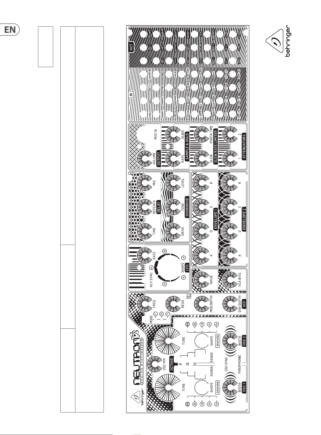
32 NEUTRON User Manual
Neutron Patch Sheet
Patch Number
DATE:
NOTES:
AUTHOR: TITLE:

33 NEUTRON User Manual
FEDErAL COmmUNICATIONS
COmmISSION COmPLIANCE
INFOrmATION
Responsible Party Name: music Tribe Commercial NV Inc.
Address: 5270 Procyon Street
Las Vegas, NV 89118
USA
Phone Number: +1 702 800 8290
NEUTrON
complies with the FCC rules as mentioned in the followingparagraph:
This equipment has been tested and found to comply with the limits for a ClassB
digital device, pursuant to part 15 of the FCC Rules. These limits are designed
to provide reasonable protection against harmful interference in a residential
installation. This equipment generates, uses and can radiate radio frequency
energy and, if not installed and used in accordance with the instructions, may cause
harmful interference to radio communications. However, there is no guarantee that
interference will not occur in a particular installation. If this equipment does cause
harmful interference to radio or television reception, which can be determined
by turning the equipment o and on, the user is encouraged to try to correct the
interference by one or more of the followingmeasures:
• Reorient or relocate the receiving antenna
• Increase the separation between the equipment and receiver
• Connect the equipment into an outlet on a circuit dierent from that to which the
receiver is connected
• Consult the dealer or an experienced radio/TV technician forhelp
This device complies with Part 15 of the FCC rules. Operation is subject to the
following two conditions:
(1) this device may not cause harmful interference, and
(2) this device must accept any interference received, including interference that may
cause undesired operation.
Important information:
Changes or modications to the equipment not expressly approved by Music Tribe
can void the user’s authority to use the equipment.
NEUTrON

We Hear You