Wireless Bridge Access Point
© 2024 TP-Link 7106511394 REV2.0.0
Note: Images may dier from your actual product.
• Lightning and ESD Protection
Before mounting the AP, consider Lightning and ESD Protection to ensure
safety. Proper grounding is extremely important for outdoor devices.
By using shielded CAT5e (or above) cable with ground wire for the
connection and the provided PoE adapter (Method 1), you can effectively
eliminate ESD attacks.
If you use the general CAT5e cable for the connection, then it is necessary
to connect the grounding terminal of the AP to earth ground through
grounding cable (Method 2).
AP
Grounding
Terminal
Earth Ground
Two Methods:
2
2
1
1
1
1
Grounded PoE Adapter
Grounding
Cable
Shielded CAT5e (or above) Cable
with Ground Wire
Grounding Terminal and Cable
Shielded CAT5e (or above)
Cable with Ground Wire
Grounded 3-Wire
Power Outlet
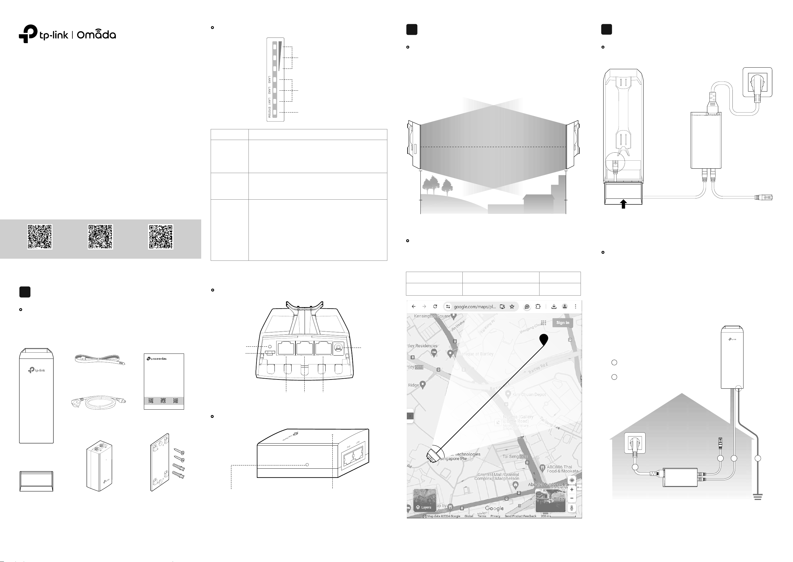
• Panel Layout
•
Passive PoE Adapter
Power LED:
On: Power on
Off: Power off
Remote Reset:
Press and hold for about 8 seconds until
the AP’s Signal and LAN LEDs flash. The
AP will restore factory settings.
RESET
Button
Grounding
Terminal
LAN1(POE IN) LAN2 LAN3
Power
Port
• Mounting Height
Site Consideration
2
Ensure a clear line of sight between the wireless devices for an optimum
performance. An elevated location is recommended as obstacles like trees,
buildings and large steel structures will weaken the wireless signal.
Line of Sight
Side View
Hardware Connection
Connect the AP and power adapter as shown in the figure below.
Connect the AP and the passive
PoE adapter with an Ethernet
cable.
Shielded CAT5e (or above) cable
with ground wire is recommended
(refer to the next section).
• For Main AP:
Connect to the
NVR/main network.
• For Client AP:
Connect to the
camera/client.
Slide back the AP cover
when all connections
are nished.
LAN1(POE IN)
PoE LAN
3
• Power Connection
•
Orientation
Install the APs with the front facing the intended signal receiving devices.
You can orient the APs with the assistance of Google Maps, GPS and some
landmarks according to the horizontal beamwidth listed below.
A
B
Line of Sight
Horizontal
Beamwidth
Model EAP115-Bridge/EAP215-Bridge
35° 70°
EAP211-Bridge
Horizontal Beamwidth
• LED Explanation
* When the Locate feature is activated in the Omada Controller, the AP’s SYSTEM LED
will ash quickly for 10 minutes to help you locate and identify the device. You can
disable this feature manually to stop the device from ashing.
Signal LEDs
LAN LEDs
SYSTEM LED
Work as Main AP:
All LEDs remain solid on.
Work as Client AP:
More lit LEDs indicates better wireless signal strength.
On: The port is connected, but not active.
Flash: The port is connected and active.
O: The port is not connected.
On: Working normally/Initializing
O: Working abnormally/Power o/LED is turned o.
Flash:
• Flash twice: Initialization is completed.
• Flash quickly: The AP is resetting, or the Omada
Controller is locating the device*.
• Flash once per second: The AP is upgrading.
• Sustained Flash: The AP is in the isolated state.
Signal LEDs
LED Indication
LAN LEDs
SYSTEM LED
• Package Contents
Overview
1
We offer single-pack and KIT products. You can purchase according to
actual needs. The KIT product will contain two sets of accessories and
one Installation Guide.
AP
AP Cover
Pole Mounting Strap
Power Cord
Passive PoE Adapter Mounting Kits
(for Adapter)
Installation Guide
Indoor/Outdoor Access Point/Wireless Bridge
Note: Images may dier from your actual product.
Quick Installation Guide
Business CommunityDownload CenterSetup Videos
Note: Accessories may vary by product.
Quick Installation Guide
Business CommunityDownload CenterSetup Videos
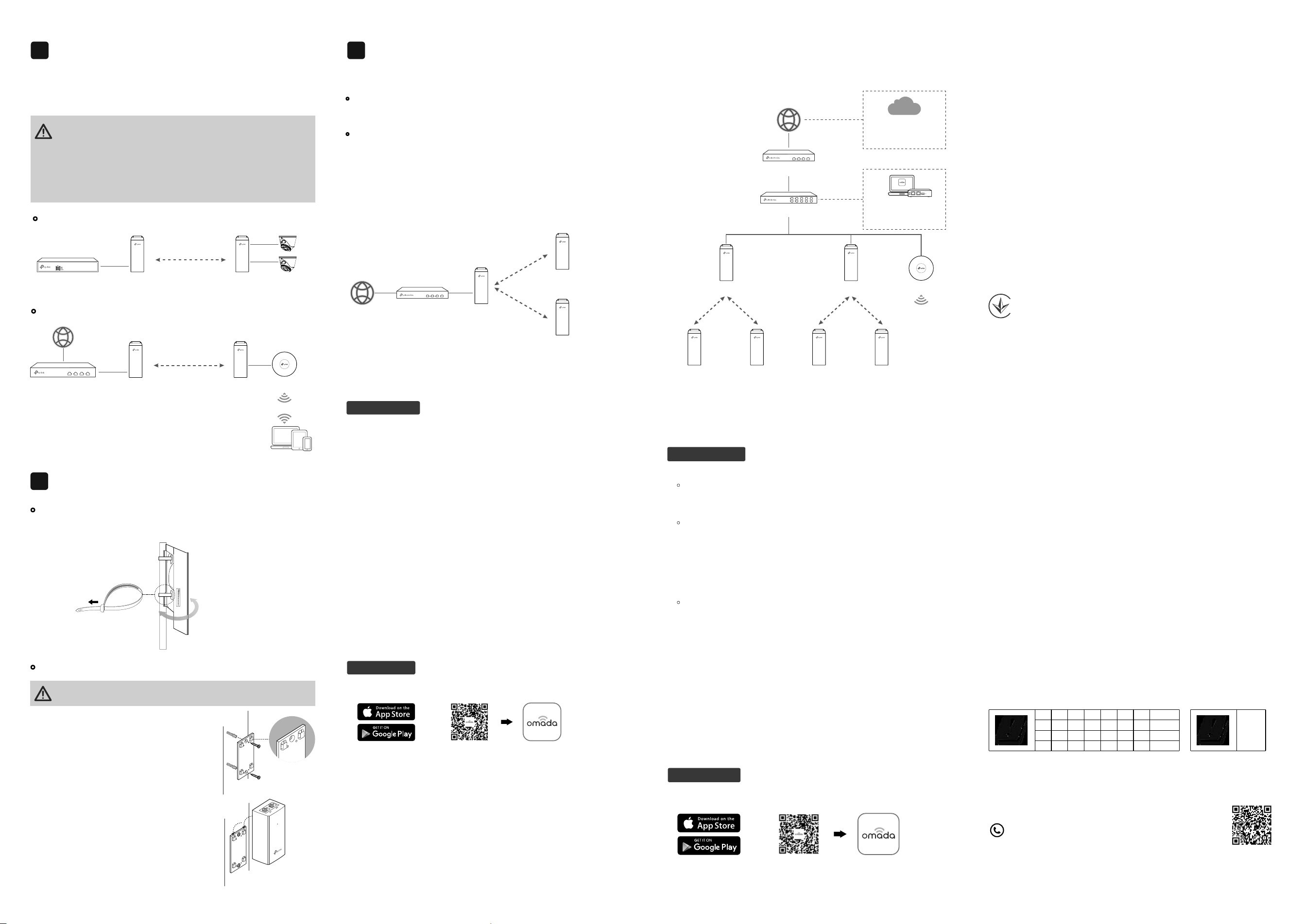
• Mount the AP
At the selected site, approximately align the AP to the direction that you
have oriented.
• (Optional) Mount the Power Adapter
To ensure the passive PoE adapter is attached most securely, we
recommend that you install the adapter with the Ethernet port facing upward.
Mounting
5
1. Drill two holes on the wall and insert the wall
anchors into the holes. Secure the
mounting bracket to the wall. Make sure the
shoulders at the corners of the mounting
bracket are on the outside and pointing
upward.
2. Attach the passive PoE adapter to the
mounting bracket by sliding the adapter in
the direction of the arrows until it locks into
place.
After power-on, Bridge APs in the same KIT will automatically form a bridge
network. The Signal LEDs on the APs will turn on.
Note: If you have other Bridge APs, refer to the Network Management section to add
them manually.
Auto Pairing
4
• Typical Application 2: Wi-Fi Extension
Gateway/Router
Clients
AP
Main AP Client AP
Auto Pairing
• Typical Application 1: Remote Camera Monitoring
Main APNVR Client AP Cameras
Auto Pairing
1. The default SSID on the product is only for device access and
management. If you need an SSID to access the internet and service
networks, refer to the Network Management section to set up the AP.
2. In a network without a DHCP Server, Bridge APs will use the following
DHCP fallback IP addresses:
Main AP: 192.168.0.254
Client AP: 192.168.0.253
If you want to change AP settings, manage the network, or add other APs to
the network, choose a method below:
•
Method 1: Standalone Mode
Congure and manage APs through the Main AP (Convenient for a small
network with only a few devices)
•
Method 2: Controller Mode
Congure and manage APs in batches on a central platform, namely the
Omada Controller.
Via Web Browser
1. Connect your management device to the Main AP by using the default
SSID printed on the label of the product.
Note: Under factory settings, the AP’s management SSID will disable after two hours
upon powering on. If you need to connect to the SSID, re-power the AP.
2. Launch a web browser and enter https://tplinkeap.net in the address bar.
If your network doesn’t have a DHCP server, ensure your management
device is using IP address 192.168.0.X, then enter https://192.168.0.254
instead to access the AP’s web page.
3. Use admin for both Username and Password to log in. Set up a new
Username and Password for secure management purpose. Then you can
configure the Main AP.
4. Add the Client AP(s).
• For the Client AP in the same KIT as the Main AP, the system will
automatically scan for it and add it to the network.
• For other Bridge APs, go to Management > Wireless Bridge APs, then
click Add Client AP and follow web instructions to manually add them to
the network.
Notes:
1. For security, we recommend changing the default login username and password of
each AP. The Main AP’s Bridge AP list provides quick access to each AP’s web page.
2. Bridge KIT APs have factory-set roles. If you want to change their roles, refer to the
User Guide at: https://www.tp-link.com/support/download/?type=smb
1. Download and install the TP-Link Omada App from App Store or Google
Play.
2. Connect your mobile device to the Main AP by using the default SSID
printed on the label of the product.
Note: Under factory settings, the AP’s management SSID will disable after two hours
upon powering on. If you need to connect to the SSID, re-power the AP.
3. Open the Omada App, go to the Standalone Mode > EAPs page, and wait
for the Main AP to appear. Tap on the AP to congure it.
4. Add the Client AP(s).
• For the Client AP in the same KIT as the Main AP, the app will
automatically scan for it and add it to the network.
• For other Bridge APs, go to the EAPs page, tap Bridge, then tap + and
follow app instructions to manually add them to the network.
Note: For security, we recommend changing the default login username and
password of each AP.
Scan for Omada Omada
or
Via Omada App
Method 1: Standalone Mode
Notes:
• Before you start, be sure to power up and connect your devices according to the
topology gure.
• A DHCP server (typically a gateway/router with the DHCP function enabled) is
required to assign IP addresses to the APs and clients in your local network.
If your network has only a few devices, you can congure and manage
Bridge APs through the Main AP.
Note: The AP’s web page is inaccessible while the AP is managed by a Controller.
Internet Gateway/Router
Main AP
Client AP
Client AP
(Optional) Network Management
6
Method 2: Controller Mode
Notes:
• A DHCP server (typically a gateway/router with the DHCP function enabled) is required
to assign IP addresses to the APs and clients in your local network.
• The Omada Controller must have network access to your Omada devices (the
gateways/routers, switches, and APs) in order to nd, adopt, and manage them.
Omada Controller integrates Omada gateways/routers, switches, access
points, and more for centralized management.
1. Get an Omada Controller ready.
•
Option 1: Omada Hardware Controller
Obtain a Hardware Controller and refer to its Installation Guide to set it
up.
•
Option 2: Omada Software Controller
On a PC with Windows or Linux OS, download the Software Controller
from https://www.tp-link.com/support/download/omada-software-
controller/. Then run the file and follow the wizard to set up the
Controller.
Note: To manage your devices, the Software Controller needs to keep running on
your PC.
• Option 3: Omada Cloud-Based Controller
Go to the Omada Portal (https://omada.tplinkcloud.com) and log in with
your TP-Link ID. Then click + Add Controller to add a Cloud-Based
Controller and set it up.
2. Launch the Controller, access your site, and go to the Devices page.
3. Now you can adopt and manage the APs.
Note:
Bridge KIT APs have factory-set roles. If you want to change their roles, refer to the
User Guide at: https://www.tp-link.com/support/download/?type=smb
Tip:
For the Omada Hardware/Software Controller, you are recommended to enable
Cloud Access and bind it to your TP-Link ID. This enables you to remotely access
and manage the Controller and Omada devices via the Omada Portal
(https://omada.tplinkcloud.com).
Via Web Browser
1. Download and install the TP-Link Omada App from App Store or Google
Play.
Scan for Omada Omada
or
Via Omada App
2. Add the Controller with local access or cloud access.
• Local Access
Note: Local access applies to the Hardware Controller and Software Controller
only.
a. Connect your mobile device to an AP in your network.
Note: If you connect to a Bridge AP, ensure you have set up it first. The default
SSID on the product is isolated from service networks.
b. Launch the Omada App and go to Controller - Local Access. Tap the
+ button on the upper-right corner to add the Controller.
• Cloud Access
a. Launch the Omada App and go to Controller - Cloud Access.
b. Log in with your TP-Link ID. A list of Controllers that have been bound
with your TP-Link ID will appear.
3. Launch the Controller, access your site, and go to the Devices page.
4. Now you can adopt and manage the APs.
The Omada App is designed to help you quickly configure common
settings. If you want to configure advanced settings, use the web page
of your Controller.
TP-Link hereby declares that the device is in compliance with the essential
requirements and other relevant provisions of directives 2014/53/EU, 2009/125/EC,
2011/65/EU and (EU)2015/863. The original EU Declaration of Conformity may be
found at https://www.tp-link.com/en/support/ce/.
TP-Link hereby declares that the device is in compliance with the essential
requirements and other relevant provisions of the Radio Equipment Regulations
2017. The original UK Declaration of Conformity may be found at
https://www.tp-link.com/support/ukca/
Attention: In EU member states, EFTA countries and Northern Ireland, the operation
in the frequency range 5150MHz-5350MHz is only permitted indoors.
Attention: In Great Britain, the operation in the frequency range 5150MHz - 5350MHz
is only permitted indoors.
For AP Controller, go to the Devices page and select the desired AP to specify the
channel.
For web browser, go to Wireless > Wireless Settings to specify the channel.
Safety Information
• Keep the device away from fire or hot environments. DO NOT immerse in water or
any other liquid.
• Do not attempt to disassemble, repair, or modify the device. If you need service,
please contact us.
• Do not use the device where wireless devices are not allowed.
• Do not use damaged charger or USB cable to charge the device.
• Do not use any other chargers than those recommended.
• Adapter shall be installed near the equipment and shall be easily accessible.
• Use only power supplies which are provided by manufacturer and in the original
packing of this product. If you have any questions, please don't hesitate to contact
us.
• Adapter should be used indoors where the ambient temperature is lower than or
equal to 40℃. Outdoor products are powered through the adapter's output line.
• The plug on the power supply cord is used as the disconnect device, the
socket-outlet shall be easily accessible.
• This equipment can be powered only by equipments that comply with Power Source
Class 2 (PS2) or Limited Power Source (LPS) defined in the standard of IEC
62368-1.
• Plug the adapter into the wall outlets with earthing connection through the power
supply cord.
AT
EE
IS
NO PL PT RO SE SI SK UK(NI)
IT LI LT LU LV MT NL
EL ES FI FR HR HU IE
BE BG CH CY CZ DE DK
UK
For detailed configurations, refer to the user guides of the Controller and
APs. The guides can be found at our Download Center:
https://www.tp-link.com/support/download/?type=smb.
For technical support, the user guide and other information,
please visit https://www.tp-link.com/support/?type=smb,
or simply scan the QR code.
Gateway/Router
Switch
Main AP
Client AP Client AP
Main AP
Client AP Client AP
AP
Omada
Hardware/Software
Controller
Omada
Cloud-Based
Controller
Or
Controller