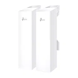
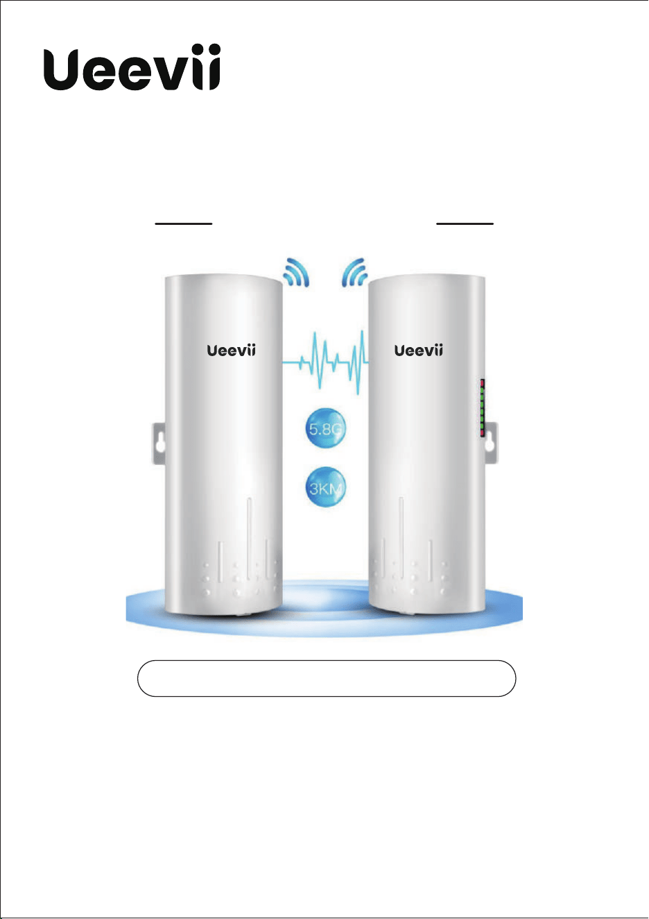
WIRELESS BRIDGE
Tips:
Thank you for ordering and using UeeVii CPE820 Wireless Bridgge, please read
the manual carefully before use. If there are any problems during the use,
please contact us in time. The installation of this device requires some network
knowledge. If you can't install it, please let us know or contact a professicnal.
This manual is a universal version for CPE820, CPE830, and CPE850. The manual
content uses the CPE820 model and pictures as examples.
Customer Service Email: [email protected]
Model: CPE820/CPE830/CPE850
USER MANUAL

OVERVIEW
1. Introduce
UeeVii CPE820 is a long-distance 5.8G wireless transmission deviice.
It uses wireless communication technology to transmit network data
using airas a medium to perform long-distance point-to-point or
point-to-mutipoint inter connection. The working data link layer realizes
the interconnection cflocal area networks. The transmission distance
can reach up to3km CPE820 Video Bridge Transmission usually consists
of two devices in AP and Client mode respectively. On the Client-side
(Receiving side) CPIE connects with IP Camera, at the AP side
(Transmitting side) CPE connects witha video recorder. The AP can be
receiving wireless data transmitted from multiple
Clients, and it is easy and convenient for centralized management of
the remote equipment.
CPE is widely used in highways, reservoir river monitoring, elevaator
monitoring systems, site crane monitoring systems, port terminal
monitoring systtems, marine aquaculture monitoring systems, and so
on. Point to point extend network WiFi range, extend the network inthe
house to your barn, garage,church, warehouse, and even neighbor's
house through wireless bridge signal transmission. No need to install a
new modem and pay for it every month, saving you money.
2. Highlights
1. Transmission using 5.8Ghz wireless technology;
2. 1000MbpsRJ45 LAN port, support Gigabit;
3. Built-in 16dbi high gain WiFi antenna;
4. IEEE802.11ac IEEE802.11n,IEEE802.11a ,EEE802.3u;
5. Transmission distance up to 3km(Barrier-Free);
6. Masterbridge supports WiFi hotspot access;
7. Dialing to set the transmitter and receiver, is easy to use;
8. WDS networking mode, video network dual compatible;
9. Support point-to-point, point-to-multipoint mode;
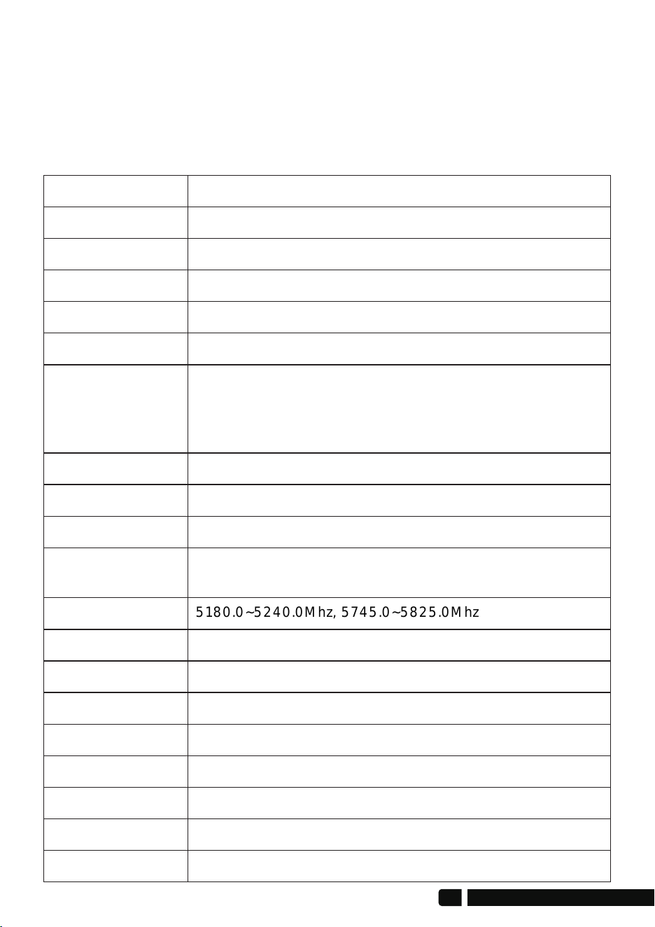
UeeViiBrand
CPE-820
7620A+7612E+IP1001
8MByte
DDR2 64MByte
10/100/1000Mbps LAN*1 & 10/100Mbps LAN*1
11a: 54M, 48M,3 6M, 24M, 18M, 12M, 9M, 6Mbps
11n: 7.2M, 14.4M, 21.7M, 28.9M, 43.3M, 57.8M, 65M, 72.2M,
14.4M, 28.9M, 43.3M, 57.8M, 86.7M, 115.6M, 130M,
144.4Mbps, 433Mbps
Direct Sequence Spread Spectrum(DSSS)
OFDM/BPSK/QPSK/CCK/DQPSK/DBPSK
IEEE802.11ac IEEE802.11n, IEEE802.11a, IEEE802.3u
CSMA/CA, TCP/IP, IPX/SPX, NetBEUI, DHCP, NDIS3, NDIS4,
NDIS5
5180.0~5240.0Mhz, 5745.0~5825.0Mhz
≤3W, 24V~48V Wide Vltage POE Injector/Switch
16dBi, Horizontal 60°/Vertical 30°
Support
Support
Model
CPU
Flash
DRAM
Interface
Data rate
Transfer method
Modulation
Protocol standard
Agreement
Frequency Range
Power
Antenna
WEP GUI
Telnet
Support
WEP 64/128bits,WPA,WPA2,802.1x
-30~65℃
11.8*11.5*2.7 inch & 2.2 LB
Serial
Safety
Temperature
Box Size & Weight
3. Specifications
10. Dynamic MIMO power saving mode (DMPS) and APSD;
1 1. Support 24V~48V POE power supply, easy to install and deploy;
12. Support WEB GUI access management device.
02
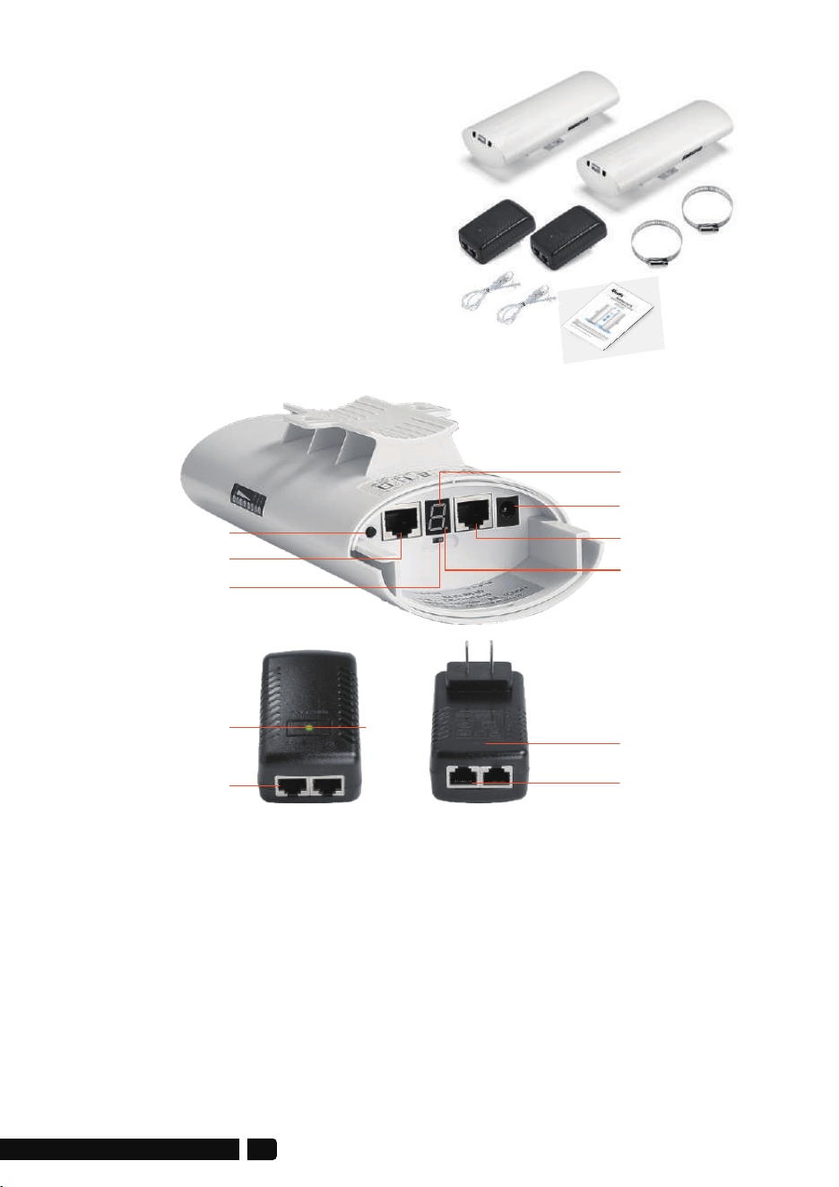
2 * CPE820 Gigabit Bridge
2 * Gigabit POE Adapter (24V)
2 * Cat 5e Network Cable
2 * Metal Hoop
1 * User Manual
4. Package Included
Reset Button:
Press and hold for 10S to reset the wireless bridge; in setup modde,
short press once to toggle a different character to pairing.
5.1. Button Operation
A-B Button:
Pushing the button to "A" indicates that the bridge acts as the master
bridge (transmitter), and pushing the button to "B" indicates that the
bridge acts as the slave bridge (receiver).
5. Interface Details
Reset Button
100Mbps LAN
A-B Button
Digital Tube
DC(Unavailable)
1000Mbps
B-LED
Gigabit PoE Adapter
LED
PoE Port
1000Mbps LAN Port
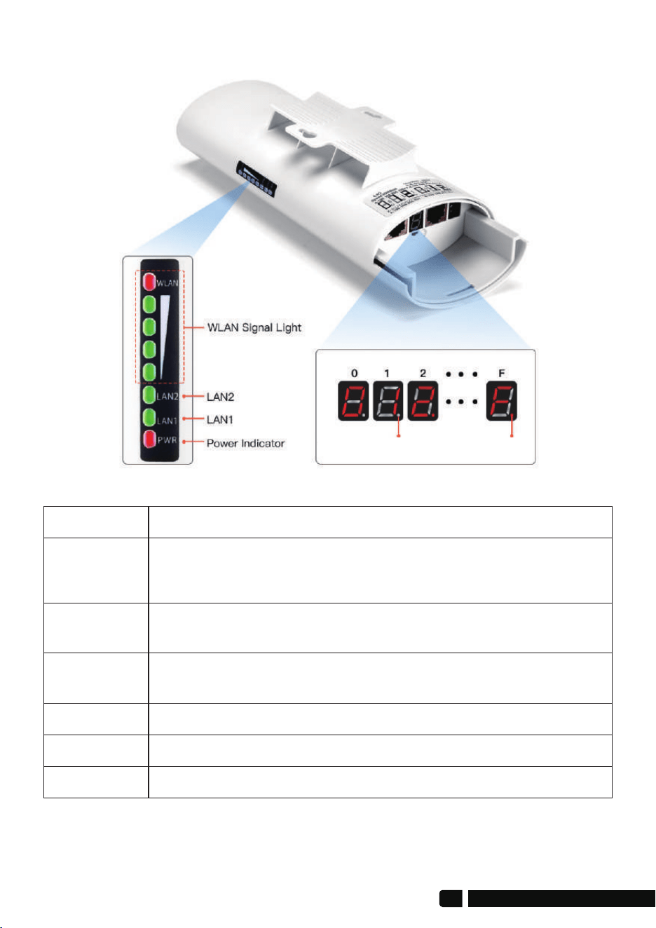
6. LED Indicator Details
Description
After the bridge is connected successfully, the WLAN light will
be on, not connected the WLAN light will not be lit.
The data connection is successful, the LED light is on,
otherwise, it is not bright.
Power indicator, the LED is on after the power is connected
The digital tube displays paired numbers and letters, 0~9, A~F.
LED Light
Signal Lights
The WLAN indicator light flashes to indicate that the wireless
function of the wireless bridge is normal, and if it does not light
up, it indicates that it is damaged.
WLAN
LAN1/LAN2
PWR
Digital Tube
A, B status lights, lighting is B mode, no lighting is A mode.Point Light
Transmitter B ModeReceiver A Mode
04
Quick Start
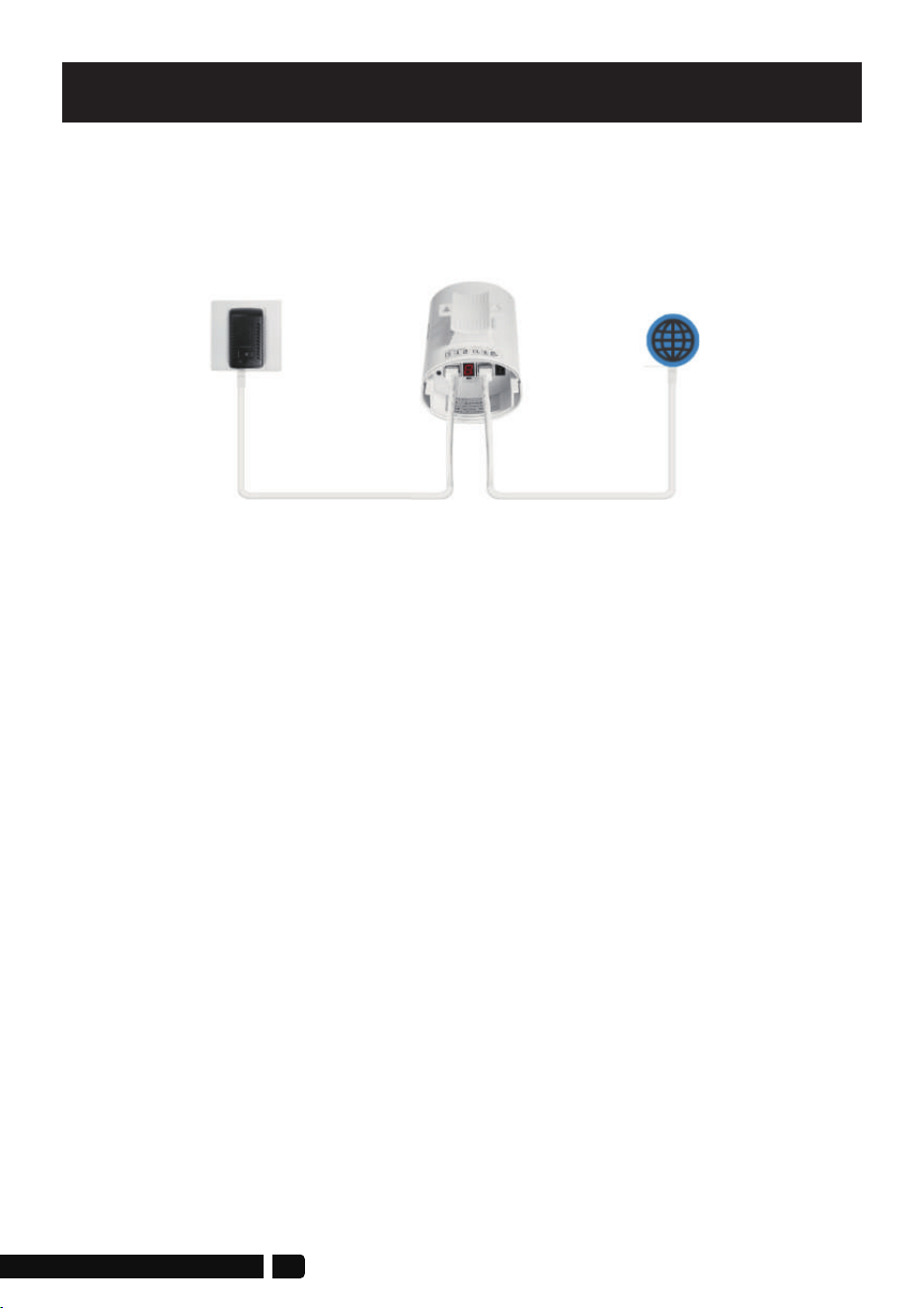
1. PoE Power Supply
The CPE820 wireless bridge adopts a POE power supply, which is easy to
install and manage while saving costs.
1.1. According to the requirements, prepare a long enough network cablle
(Recommended within 20 meters, must Cat 5e or up) to connect tiThe
wireless bridge and the PoE power supply. The PoE port of the Pobpower
supply is connected to the WAN port of the wireless bridge.
1.2. The LAN port of the PoE power supply is connected to thhe PC, router,
and switch.
3. Point to Multipoint Pairing Step:
1 master bridge with 3 slave bridges
1. Switch one unit to A(Master Bridge) and 3 units to B(Slave Bridgge);
2. Connect the POE to each unit using the Ethernet cable and plugthe POE
in;
3. Wait for them to power up, about 2 min;
4. Use the tiny reset button to click through until you get a channeI with a
letter. 1,2,3,..., A,B,C,...,F, here used C;
5. Then on the other 3 unit do the same. 4 units need to be onthe same
channel;
6. Wait for 2-5 minutes to complete the pairing. When the number of the
digital tube is solid and the signal light on the side turns on, it means
their pairing is successful;
7. Finally connect other devices(Router, PC, Switch) and install them to the
target location.
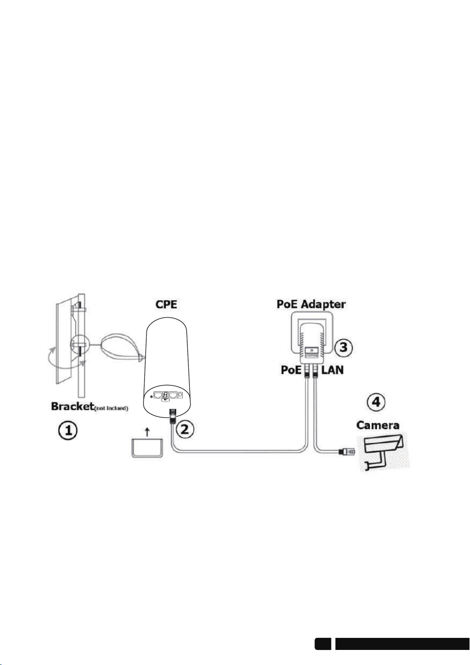
4. Installation
1. Place the CPE to the selected position and adjust the CPE front panel
orientation to be approximately the same as the selected direction,
then use the ties to fix the CPE, the bracket is not included in the package.
Recommended UeeVii Universal Bracket (ASIN: B09NLLG8MZ).
2. Please, prepare a long enough network cable to connect the PoE
adapter and CPE, the network cable is connected to the LAN port of the
CPE, and the other end is connected to the PoE port of the PoE adapter.
Recommend to use a cat 5 (or above) shielded network cable with a
ground wire
A B
06

3. Connect the PoE adapter PoE to CPE, and LAN to Camera, PC, Router or
Switch based on the network topology. The role of PoE is to provide
power and data transmission for CPE.
4. The master CPE’s PoE adapter’s LAN connection monitors the Internet,
and the slave CPE’s PoE adapter LAN connects cameras or routers and
other equipment.
5. WiFi Function
1. The WiFi function is turned on by default for the master bridge.
WiFi SSID: CPE5G-5GXXX
WiFi PWD: zllinkcpe123456XXX
XXX represents different channels, please refer to the comparison table
in the user manual.
2. You can access the wireless bridge through your computer to set the
SSID and new WiFi password. Please refer to the advanced settings
section.
For point-to-point installation, the line of sight of the 2 wireless bridge
brackets must be clear and cannot pass through the wall. The signal
transmission angle of the bridge is 60 degrees. For point-to-multipoint
installation, the angle of the slave bridge needs to be adjusted to
ensure that it is within the 60-degree signal range of the main bridge.
The antenna polarization direction is horizontal 60°/vertical 30°.
Note:
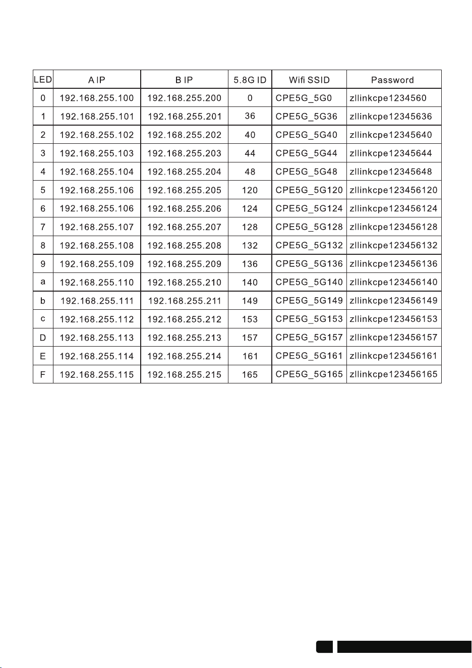
You can check the SSID and password through this chart
(Ps:In this chart, SSIDs and Passwords are the default.)
Digital & IP & WiFi Correspondence Chart
08
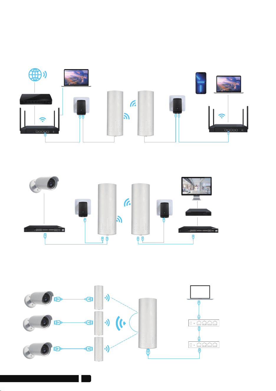
6. Application Case
suitable for extending the network to second buildings, such as garages,
shops, barns, etc.
6.1 Case 1: Point-to-point extended network WiFi range
6.2 Case 2: Point-to-point extended of surveillance cameras
range
6.3 Case 3: Point-to-multiple point extended surveillance
cameras range
Computer
Computer
Master Bridge
Phone
POELAN
POELAN
LAN Port
Slave Bridge
Router
Router
ALDS
WAN Port
Master Bridge
Master CPE
Camera 1
Camera 2
Camera 3
POE
100Mbps
100Mbps
1000Mbps 1000Mbps
POELAN
Slave Bridge
Slave CPE
Slave CPE
Switch
Switch
Switch
POE Adpater
POE Adpater
Minitor
Minitor
DVR
DVR
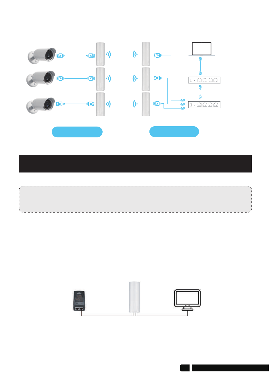
6.4 Case 4: Point-to-point extended surveillance cameras range
Advanced settings
Computer Access
Note:
You can enable the device without advanced settings.
1. Connect the CPE to the computer
Refer to the figure left to connect the CPE to the computer through a PoE
adapter and an Ethernet cable
100M port
LAN
AP
POE Charger PC
POE
1000M port
Switch
Minitor
DVR
Master CPE
Slave CPE
10
Note:
“admin” is not the password of the WiFi SSID, it is just the password for
WEB access.
2. Modify your computer's IP address,
make your computer's IP and the
bridge's IP address be on the same
network segment(LAN) so that you
can access them.
3. Change your computer's IP address to 192.168.255.xxx (192.168.255.xxx
cannot be the same as the IP of the CPE), then entry IP address is
192.168.255.xxx, subnet mask is 255.255.255.0(Autofill), Default gateway is
192.168.255.xxx, Preferred DDS server 192.168.255.xxx. You can use
192.168.255.2(xxx=2) in the reference picture to set.
4. On the login screen, the default user name and login password of the
wireless bridge is "admin", just entry password login.
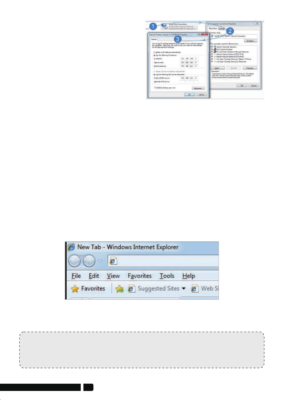
Step 1: Find and open "Open Network and Sharing Center" on your computer.
Tips: click the network icon in the lower right corner of the computer.
Step 2: Find and open the "Change adapter settings", select "Local Area
Connection" to right-click to open the network properties. Refer to the
picture above to open.
Step 3: Find and double-click open the "Internet Protocol Version 4(TCP/IPv4)",
choose the " Use the following IP address" and enter IP address, subnet
mask, Default gateway, Preferred DDS server.
192.168.255.2
5. Login successful, go to setting.
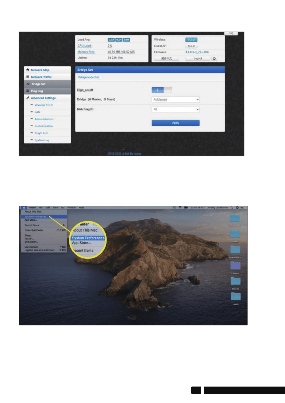
6. How to Change Your IP Address on Mac
6.1 Click the Apple icon in the upper-left corner of the screen, and select
System Preferences.
12
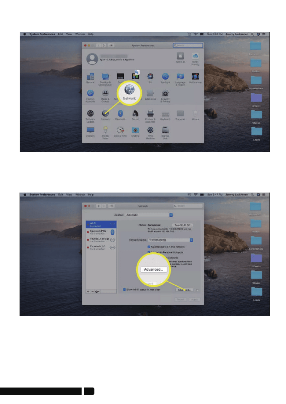
6.2 Click Network.
6.3 Click your current network on the left and then click Advanced in the
lower-right corner of the window.
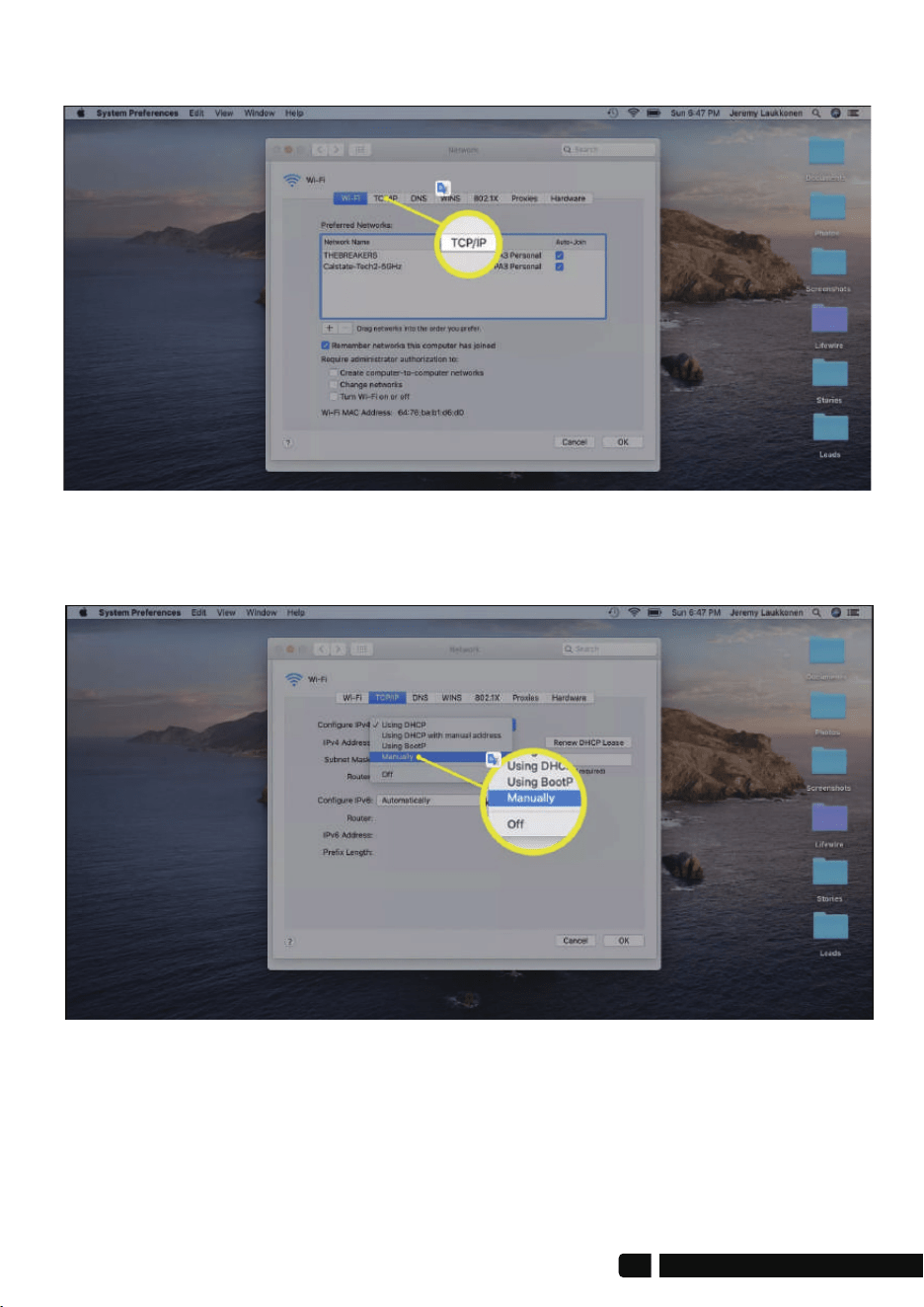
6.4 Click the TCP/IP tab.
6.5 Click the drop-down box next to Configure IPv6 (or IPv4) and select
Manually.
14
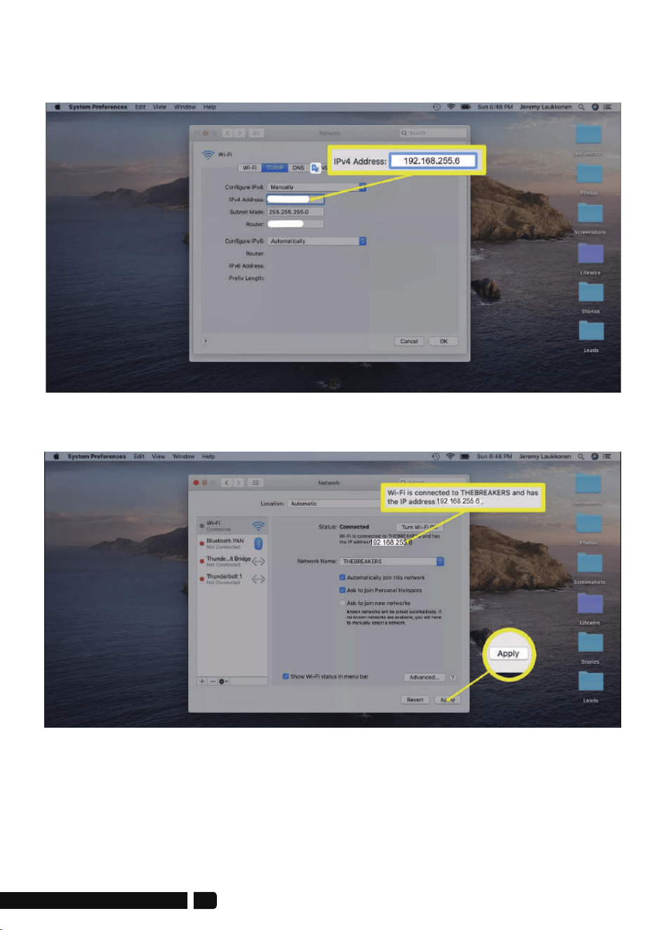
6.6 Enter the IP address you want to use
(enter 192.168.255.6; Router 192.168.255.1), and click OK.
6.7 Verify that your new local IP address is displayed and click Apply.
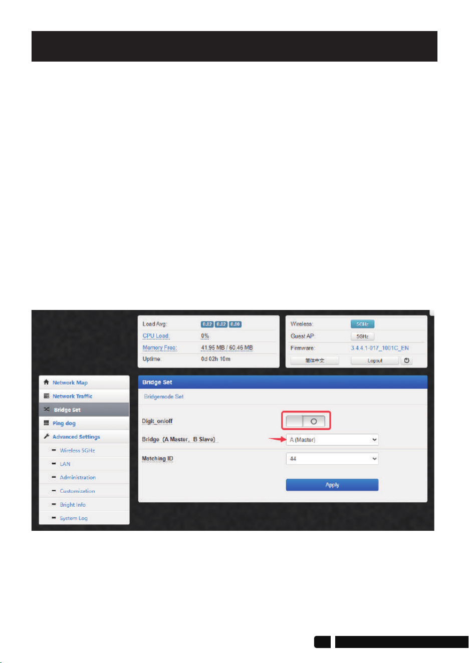
A-Master Bridge digital_on/off switch is off
1. Digital_on/off Switch Function
Setting Options
The function of the digital_on/off switch is to control the pairing by
dialing the digital switch, making the pairing simple;
When the digital_on/off switch is turned on, pairing can be done
through dialing, but any modified wireless bridge parameters cannot be
saved when the power is turned off or restarted, and the default
parameters must be used;
When the digital_on/off switch is turned off, pairing cannot be
performed by dialing the code, and the “RST” buttons will be disabled.
However, the modified wireless bridge parameters can be saved when
the power is turned off and restarted. The new pairing method is in the
Modify WiFi SSID and Password section.
Both the master bridge and the slave bridge must turn off the
digital_on/off switch before modifying the parameters.
16
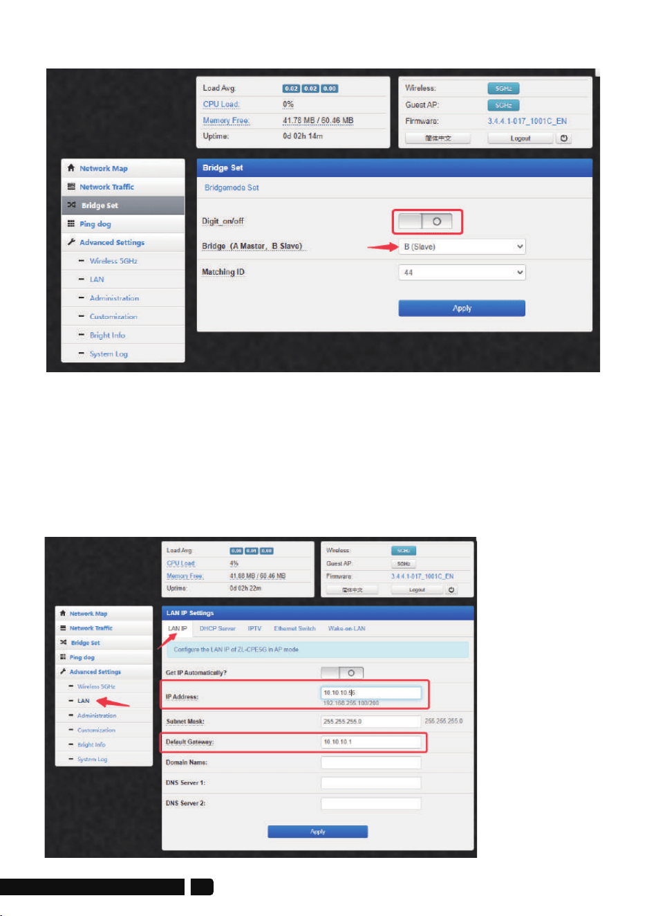
2. Modify IP Address
Modify the IP address of the wireless bridge to be compatible with your
subnet or camera/NVR. The master bridge and slave bridge must be
modified to have IP addresses in the same LAN.
For example, your network segment is 10.10.10.xxx
After the master bridge turns off the digital_on/off switch, you can set
the new IP address of the main network bridge to 10.10.10.56
B-Slave Bridge digital_on/off switch is off
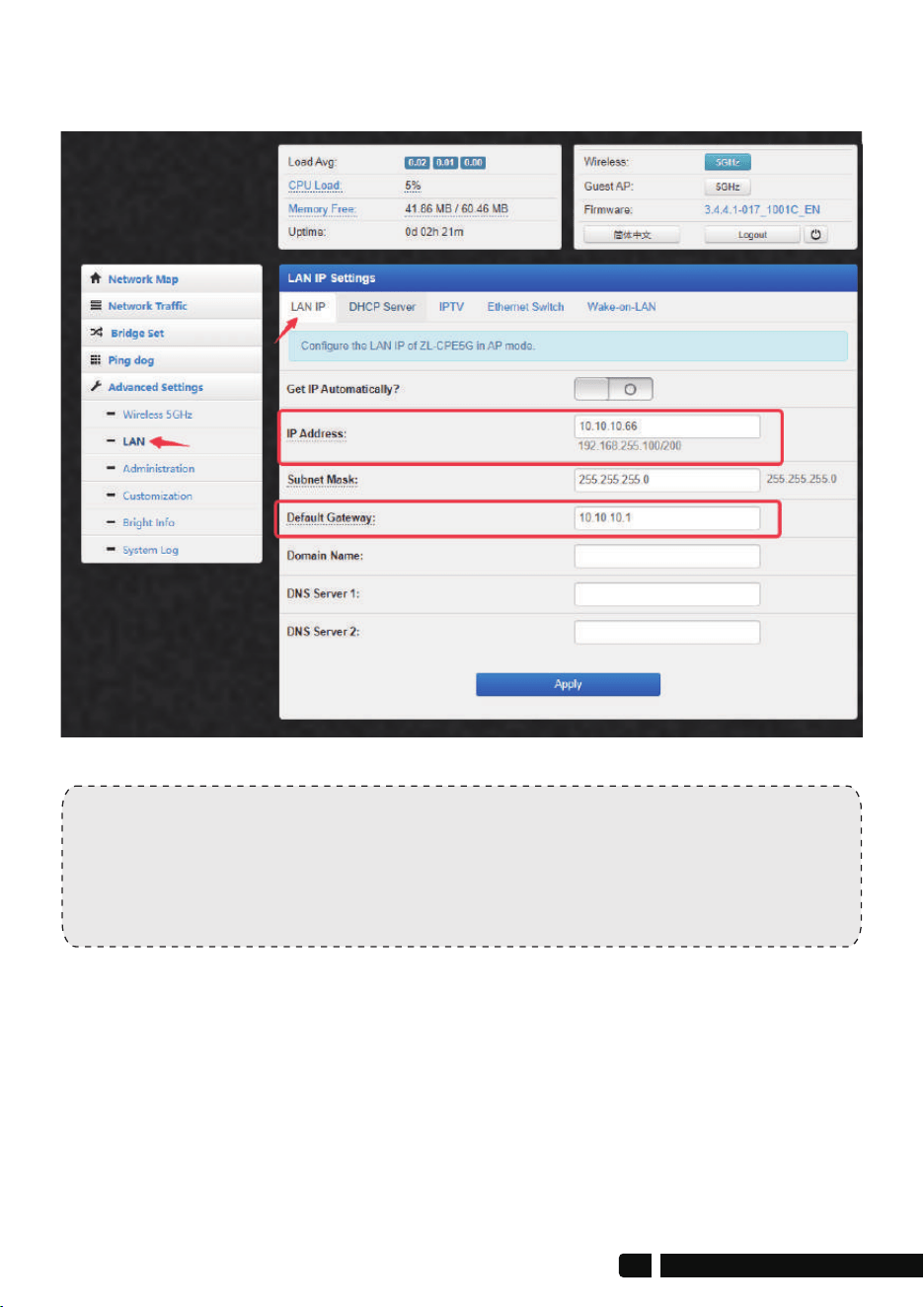
Note:
After you modify it successfully, the IPv4 address of the computer also
needs to be modified to 10.10.10.6, and then re-enter 10.10.10.56 to
access the main bridge and 10.10.10.66 to access the slave bridge.
After the slave bridge turns off the digital_on/off switch, you can set the
new IP address of the slave bridge to 10.10.10.66
18
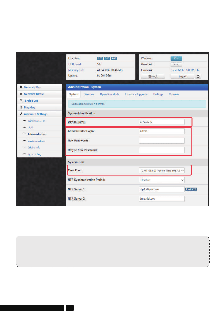
2. Modify System Info
Path: Advanced Settings>Administration-System
Here you can set the name of the device, the new login name and
password of the device, and the system time zone.
Note:
Only the master bridge of the wireless bridge broadcasts WiFi,
and the slave bridge does not broadcast WiFi by default.
4. Modify WiFi SSID & Password
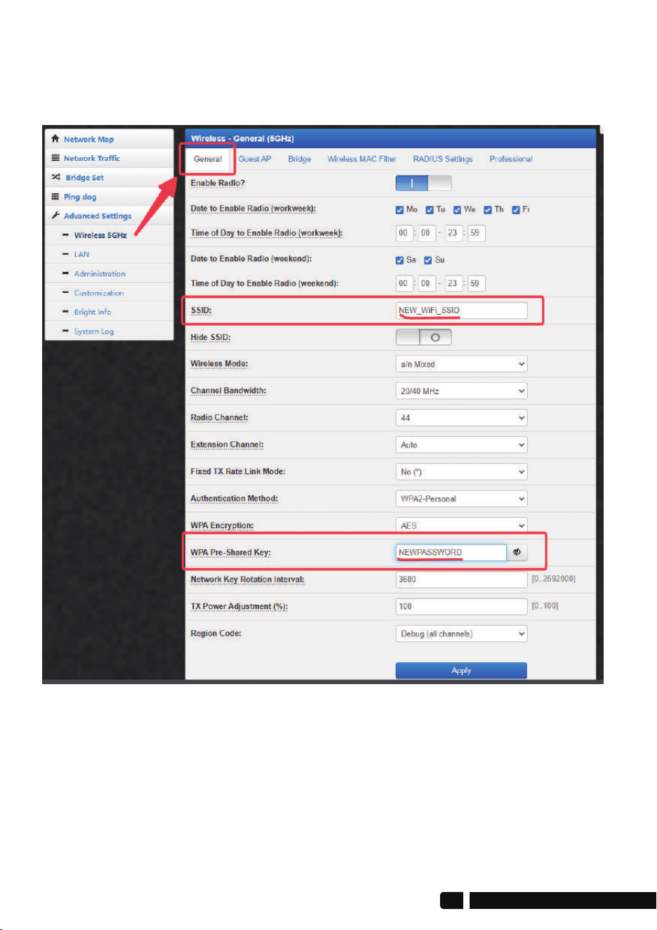
4.1. Connect the master bridge to the computer, and make sure to turn
off the digital_on/off switch, then modify the new WiFi SSID and password
in the “General” settings, save, and remember.
20
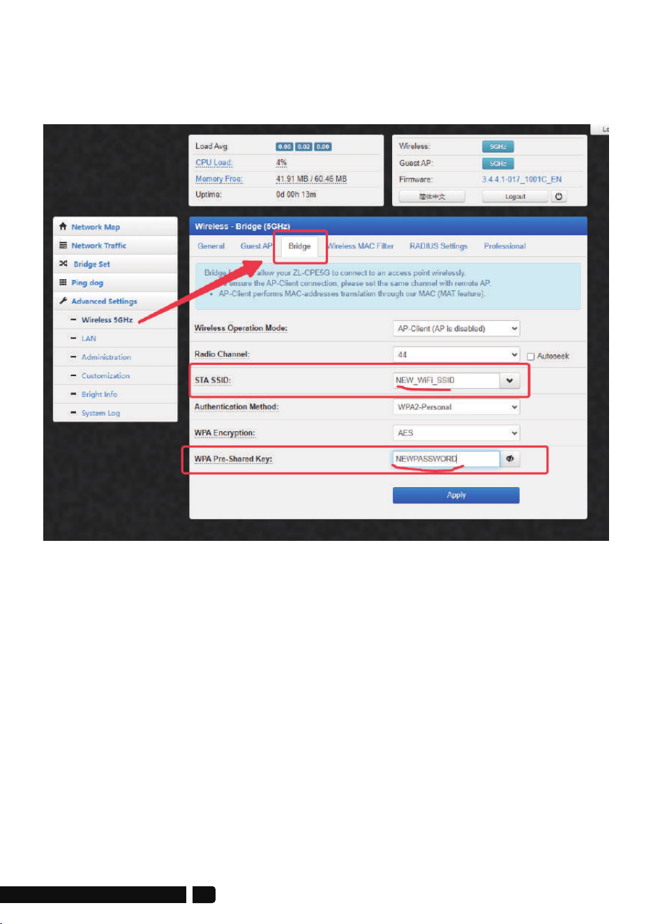
4.2.Connect the slave bridge to the computer and make sure the digital
display switch is turned off. Enter the new WiFI SSID and password of the
master bridge in the "bridge" column and save it.
4.3 Then wait for them to pair successfully. When the signal indicators on
the side of the 2 wireless bridges light up, it means the pairing is successful.
4.4 When the wireless bridge is reset, it will return to the default dial-code
pairing mode. The above settings will not be saved, but they can be saved
after a power outage reboot.
Method 1 (Recommended):
Connect a new router or AP on the slave bridge end, connect to the
WAN port, and the new router broadcasts WiFi.
It is recommended to reset the new router or AP, set it to automatically
obtain the network, and set a new SSID and password.
Method 2:
We can turn on the guest WiFi of the slave bridge and set a password.
Please refer to the following steps:
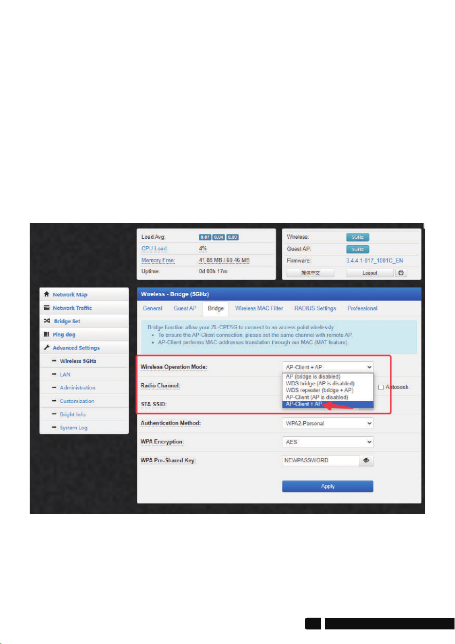
1. On the slave bridge side, path: Advanced Settings>Wireless 5Ghz>Bridge>
Wireless Operatuon Mode,must choose "AP-Client+AP" mode.
5. Slave Bridge Side Broadcasts WiFi
22
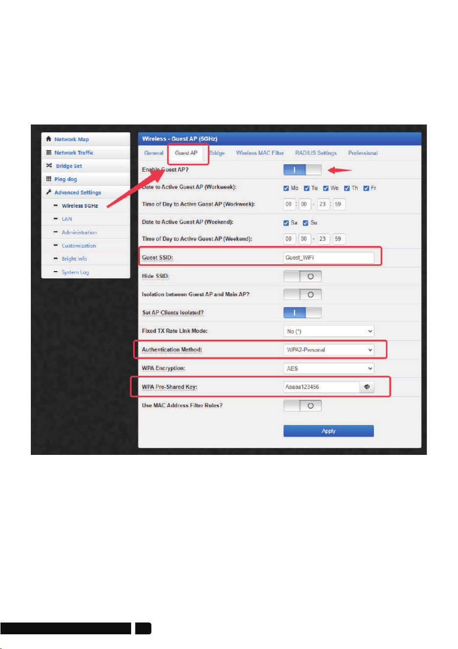
2. On the slave bridge side, path: Advanced Settings>Wireless 5Ghz>
Guest AP, Click the "Enable Guest AP?" button to turn on the guest WiFi,
then set the new guest WiFi name, encryption method and password,
and save it. Open your mobile phone's WiFi list to see the latest guest
WiFi settings, enter the password to connect and test.
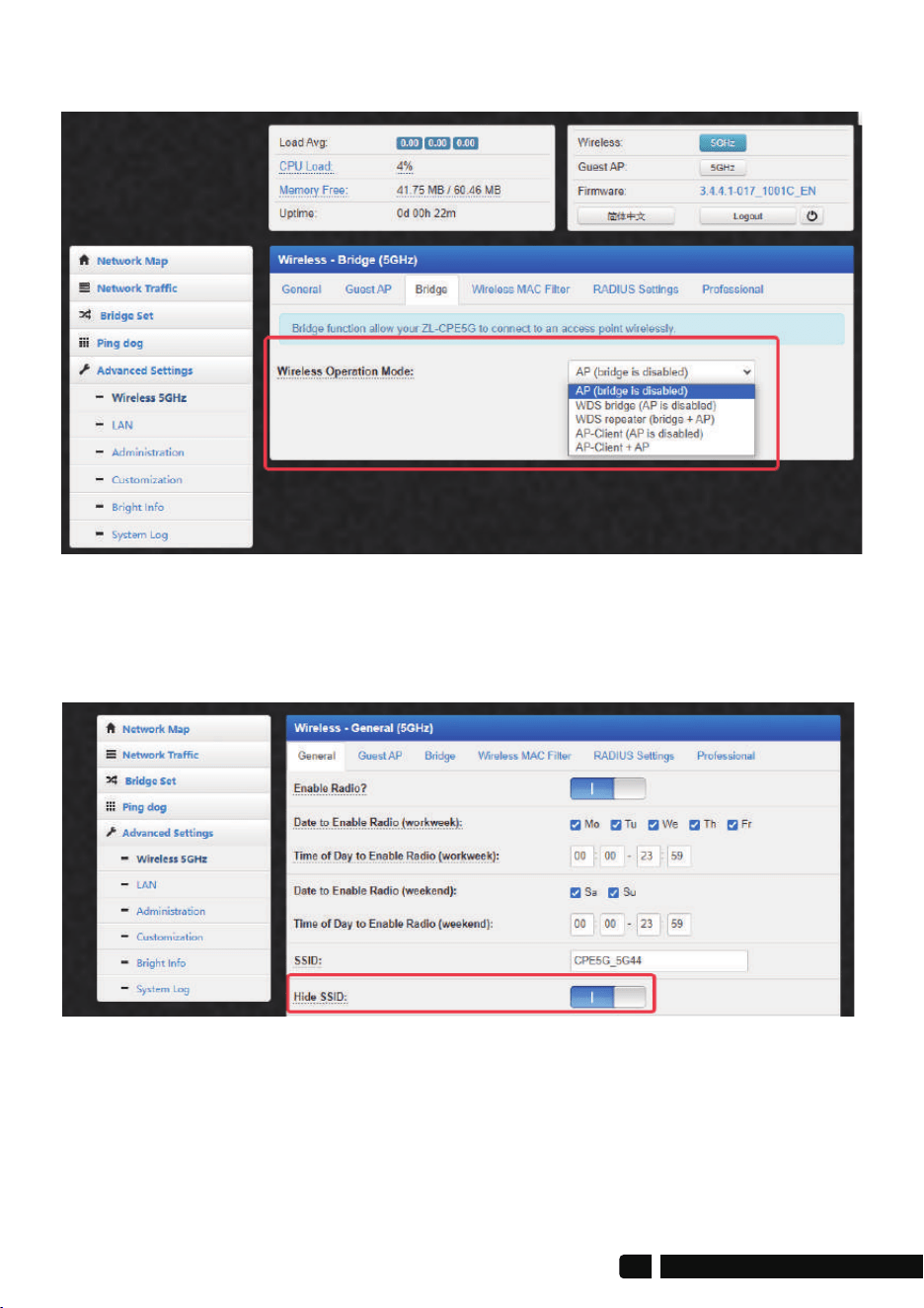
Find "Hide SSID" in the "General" column and click the button to start
hiding the SSID.
6. Wireless Mode
7. Privacy--Hidden WiFi SSID
24
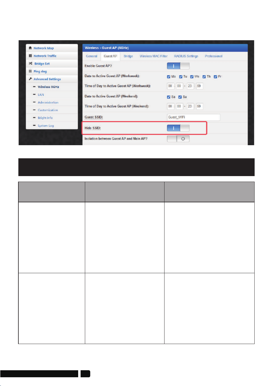
If you have guest WiFi turned on, find "Hide SSID" in the "Bridge" column
and click the button to start hiding the SSID.
Trouble
1. Use WiFi analysis to
choose the best channel
2. CPE should be in the
normal distance, and
avoid the wall
3. Adjust the angle of CPE
according to signal
strength
Reason
Solution
1. Wireless interference
2. Distance is too long,
or there are some
walls between them
3. CPE's angle in the
wrong direction,
weak signal
Packet Latency
1. Press the "RST” button
in 10s to reset the bridge,
the default password is
admin.
2. Re-input the password
3. Clear cookie, run arp -d
to clear MAC table
4. WEB access user namer
and password is "admin"
1. Forget the password
2. Input wrong password
3. Too much cookie
4. WiFi password is
confused with the
WEB access
password
Wrong Password
Troubleshooting

1. Check if the PoE adapter
or PoE switch work
2. Check if the PoE port of
CPE is ok
3. Check if Ethernet cable
is loose if Ethernet cable
plugged into PoE port
4. Check if the voltage is
normal, if the socket
has problem if the input
voltage of the PoE
adapter is normal
1. PoE power supply is
not working
2. Some problem in
CPE's PoE port
3. Ethernet cable is
loose, RJ45 port is
wrong power
current/voltage
lower or wrong
System LED light
off
1. Adjust the distance,
angle and channel to
decrease latency
2. Check if port isolated to
avoid network virus and
broadcast storm
4. Decrease the access
users.
5. Change use a Cat 5e or
above network cable.
1. Packet Latency
2. Ethernet cable circuit
3. Network virus attack
4. Too much access
users
5. Network Cables type
lower than Cat 5e?
Low transmission
Rate
1. Make CPE or PoE
adapter need a ground
connection
2. Running time over
7 days, reboot it
3. After lightning, device
PoE port broken or
unstable better to
deploy lightning
conductor
1. Static electricity
2. Running time too
long
3. Lightning stroke
Device always
dead
1. Ping 192.168.255.xxx to
see the connection
status
2. Stop other devices or
change to another IP
address
3. Check LAN connection
and Ethernet cable
4. Clear cookie, run arp-d
to clear MAC address
1. Local IP is not in the
same network
segment of CPE
2. IP is taken by other
devices
3. LAN connection or
ethernet cable has a
problem
4. Too much cookie,
MAC address haven't
update
Can not login WEB
26

WhatsAPP
Youtube
FacebookFaceBook_Grounp
Official Website
Technical Support and Service
A. Thank you for your order and for using UeeVii Wireless Bridge,
please read the manual carefully before use. If there are any problems
during the use, please contact us in time;
B. The installation of this device requires some network knowledge.
If you can't install it, please let us know or contact a professional.
Tech Service Email: [email protected]
Website: https://www.ueevii.com
FaceBook: https://www.facebook.com/UeeVii
FB Group: https://www.facebook.com/groups/8869731233069487
YouTube channel:
https://www.youtube.com/channel/UCvcFqnEd44EJWDrBIb7wxWQ