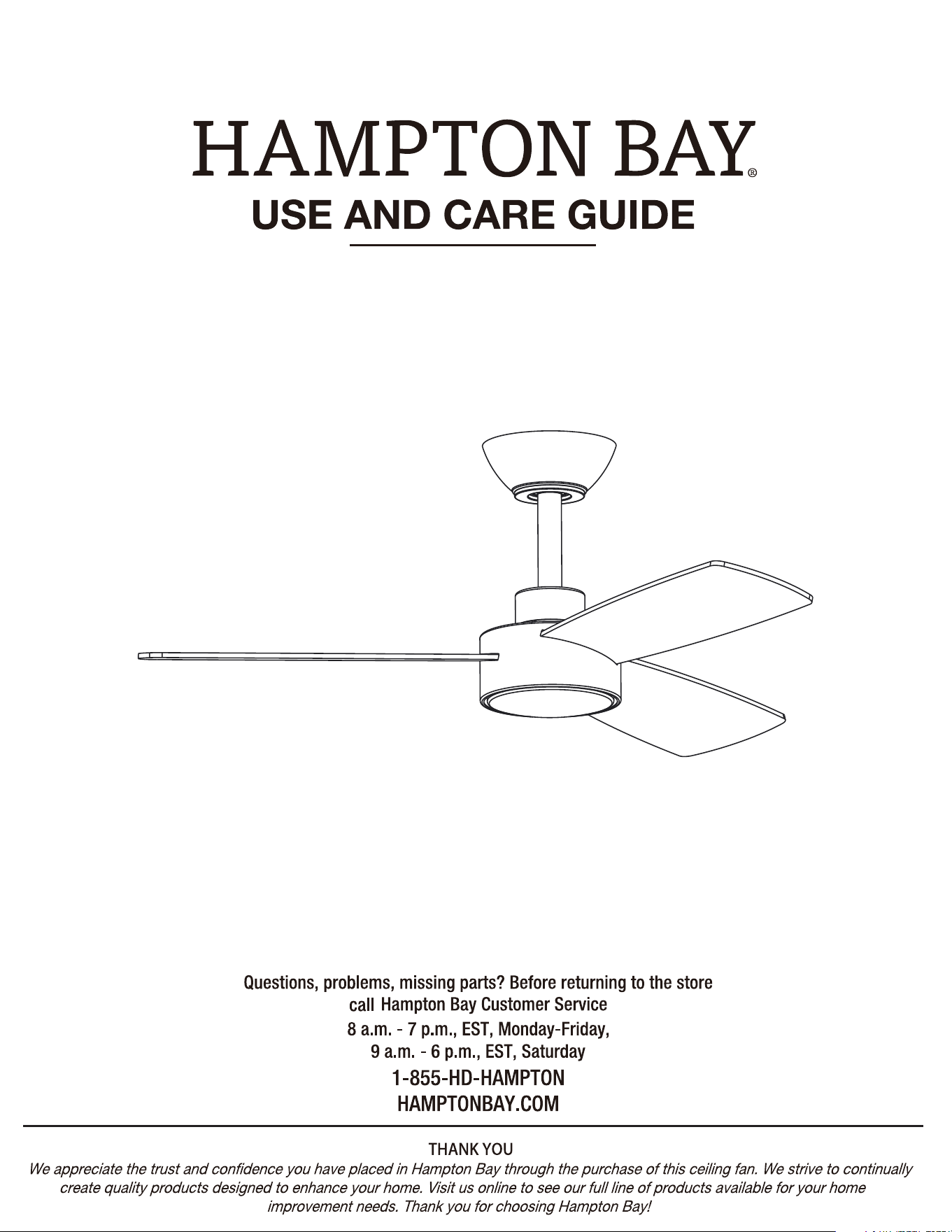
Model#X4722
SKU #1012 002 052
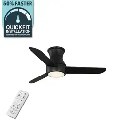
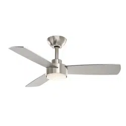
DORSEY 36 INCH INDOOR/COVERED OUTDOOR CEILING FAN
2
2
3
4
4
4
4
5
6
7
8
8
13
13
14
17
18
19
Attaching the Light Shade
3
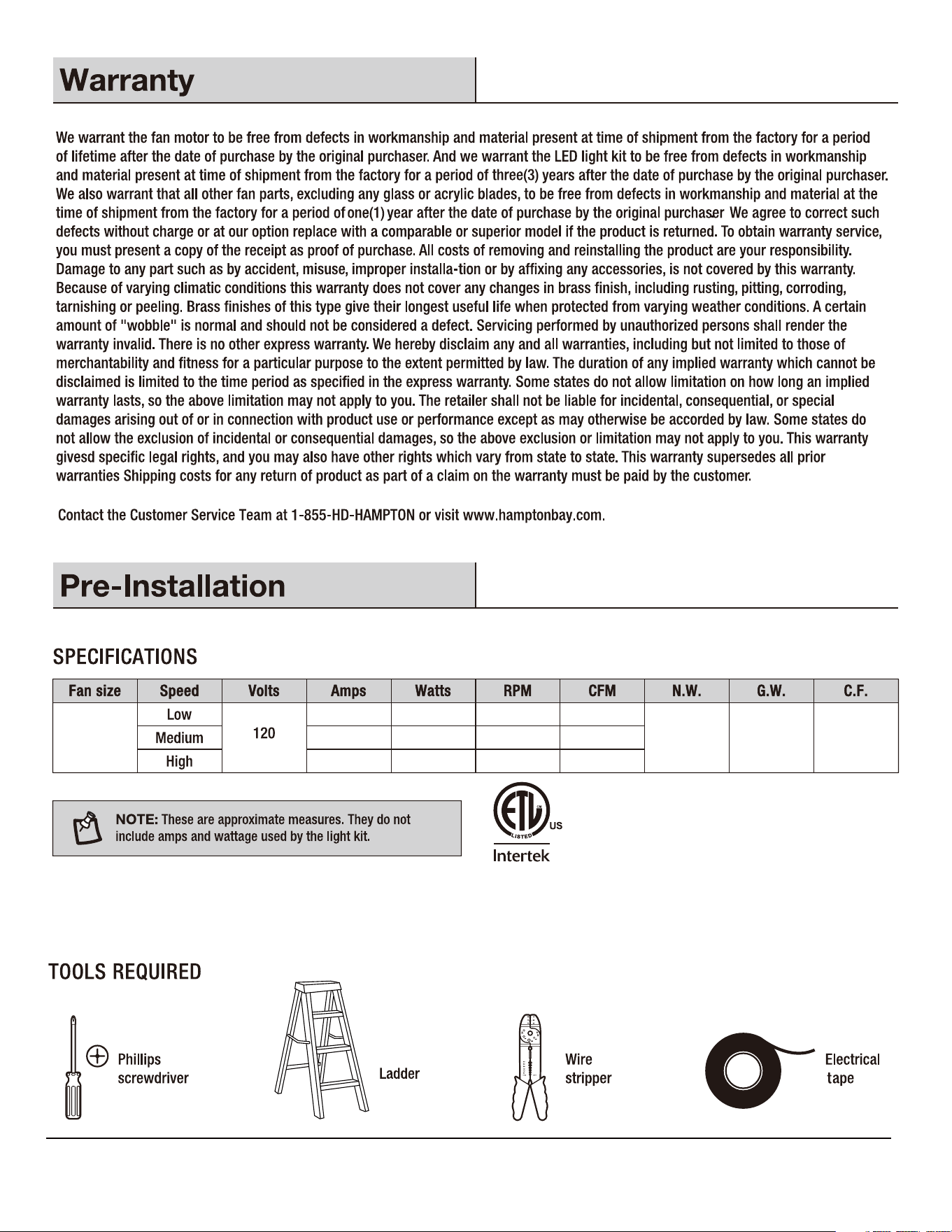
0.81 cu ft.
0.05 3.2 127 1224
0.18 12.08
260
2507
0.39 27.50 328 3220
4.55 kgs
(10.03 lbs)
3.22 kgs
(7.10 lbs)
36 in.
4
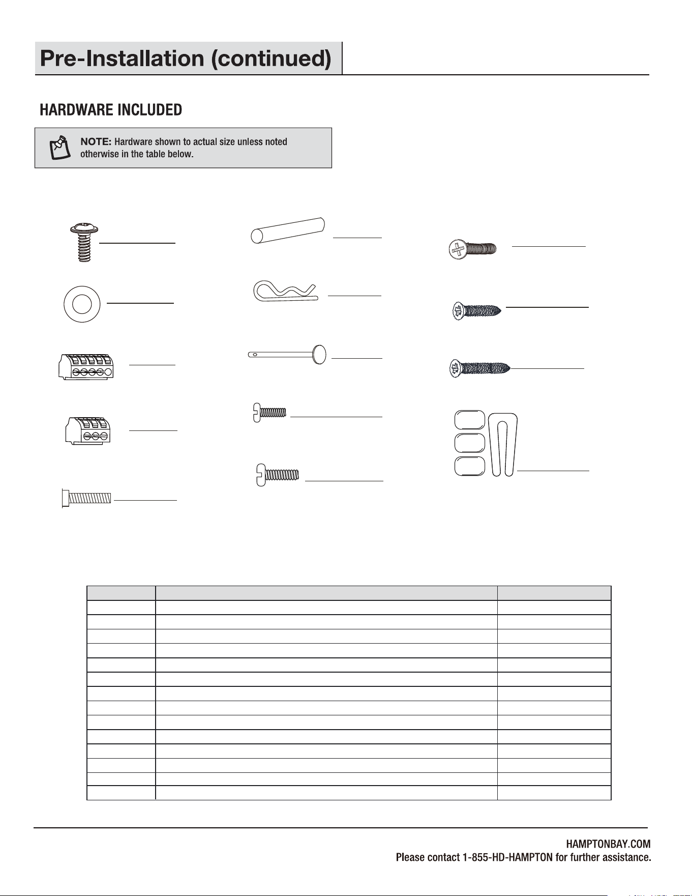
Fiber washer
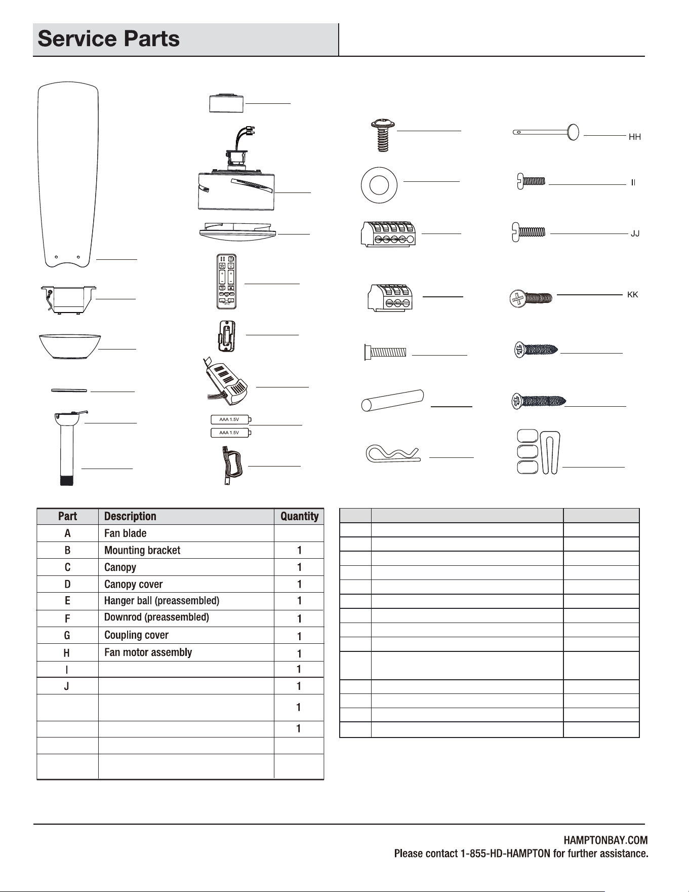
Part
Blade screw (3/16 in. x 12 mm)
Description
3 Pin Quick Connector
Mounting bracket screw (preassembled)
Cross pin (not to scale) (preassembled)
Hitch pin (preassembled)
Lock pin (not to scale) (preassembled)
Hanger ball set screw (preassembled)
Fan motor assembly coupling set screw (preassembled)
Quantity
AA
BB
CC
DD
EE
FF
GG
HH
II
JJ
KK
LL
MM
1
3
2
1
1
1
1
2
2
2
2
AA
BB
CC
DD
EE
FF
GG
HH
II
JJ
KK
LL
MM
Machine screw
Short tapered screw
Long tapered screw
5
7
5 Pin Quick Connector
7
NN
NN
1Balance kit (not to scale)
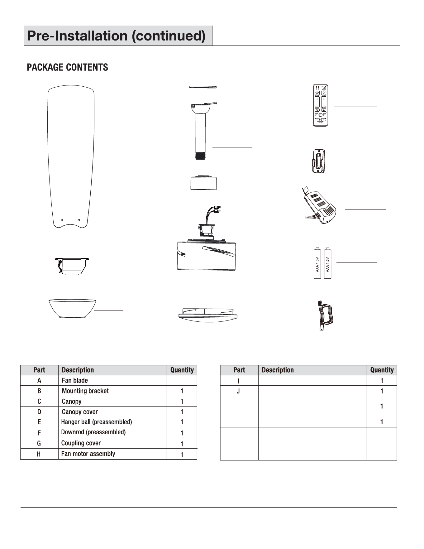
A
B
C
D
E
F
G
H
I
J
K
K
M
N
N
L
L
Remote control wall cradle with toggle
switch spacer included
Receiver
M
1.5V AAA battery
3
Light shade
Remote control
1
Extension power cord use for longer
downrod(longer downrod not included)
6
2
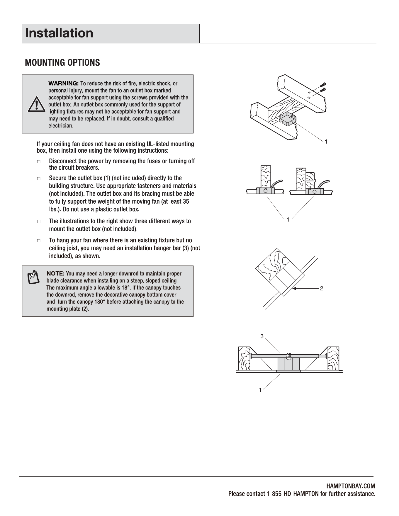
7
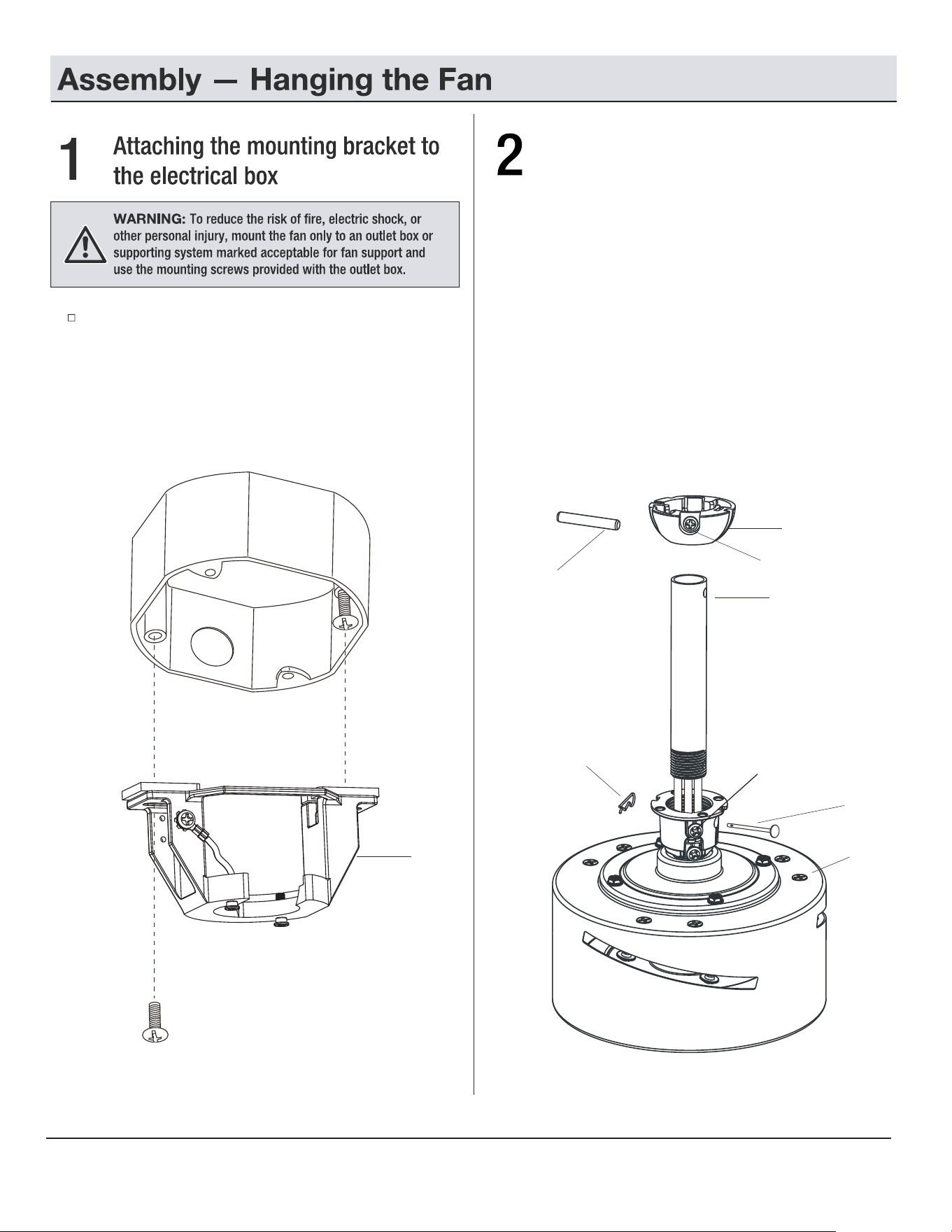
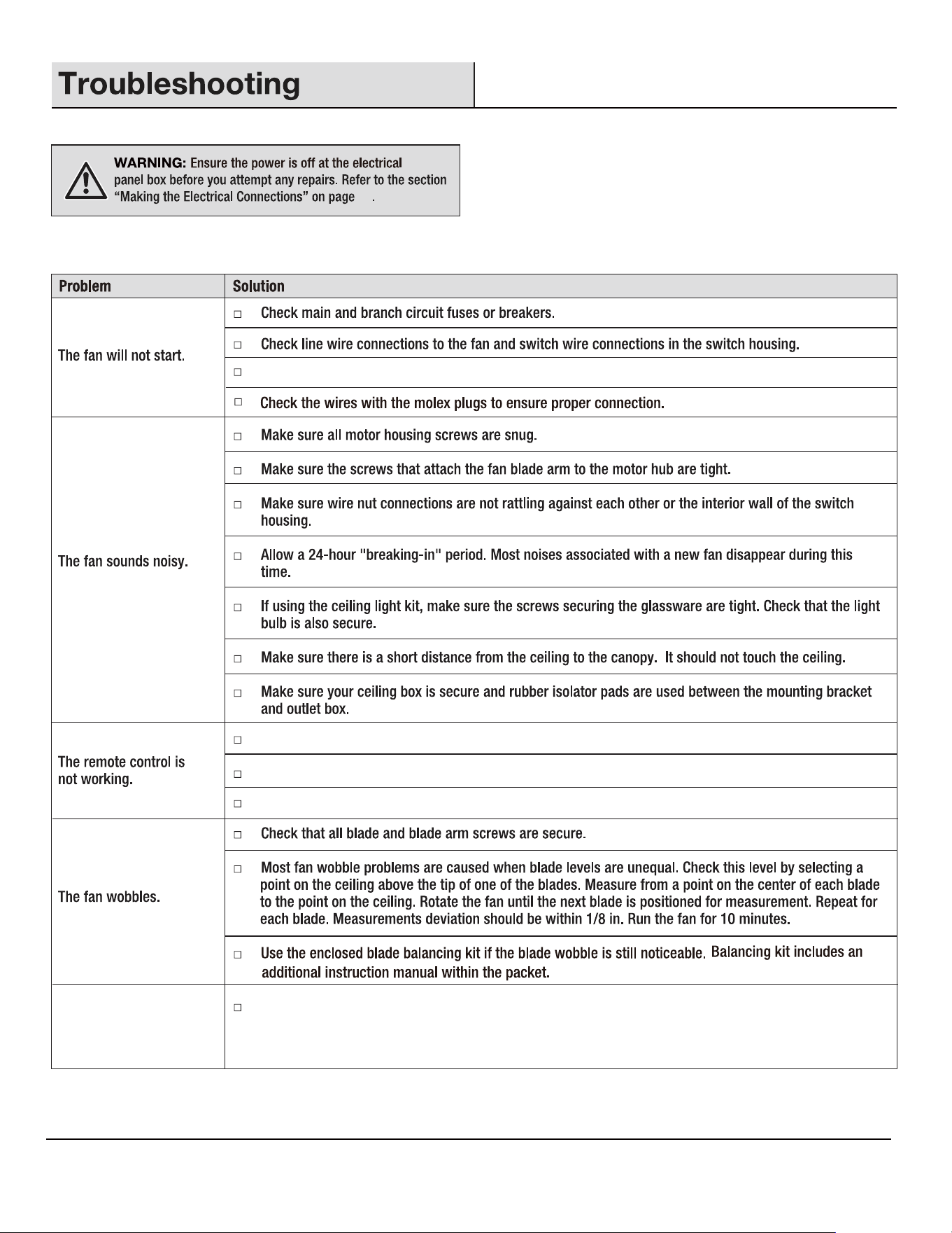
Pass the 120-Volt supply wires through the center hold in
the semi slide-on mounting bracket (B). Remove one of the
screws provided with the outlet box and loosen the other one,
sliding the semi slide-on mounting bracket (B) over the screw
previously loosened. Secure the bracket by replacing the screw
previously removed and tightening the screw previously
loosened.
8
E
F
II
FF
Attaching the downrod to the fan
motor assembly
B
□
Loosen the two set screws (JJ) from the fan motor
assembly (H) coupling. Remove the hitch pin (GG)
and lock pin (HH) from the fan motor assembly (H).
□
Remove the hanger ball (E) from the downrod (F) by
loosening the hanger ball set screw (II), and removing
the cross pin (FF), then sliding the hanger ball (E) off
of the downrod (F).
□
Carefully feed the fan wires up through the downrod (F).
Thread the downrod (F) into the fan motor assembly (H)
coupling. Line up the holes and replace the lock
pin (HH) and the hitch pin (GG).
Tighten the set screws (JJ).
HH
GG
H
JJ
G
H
E
B
OO
F
H
D
C
E
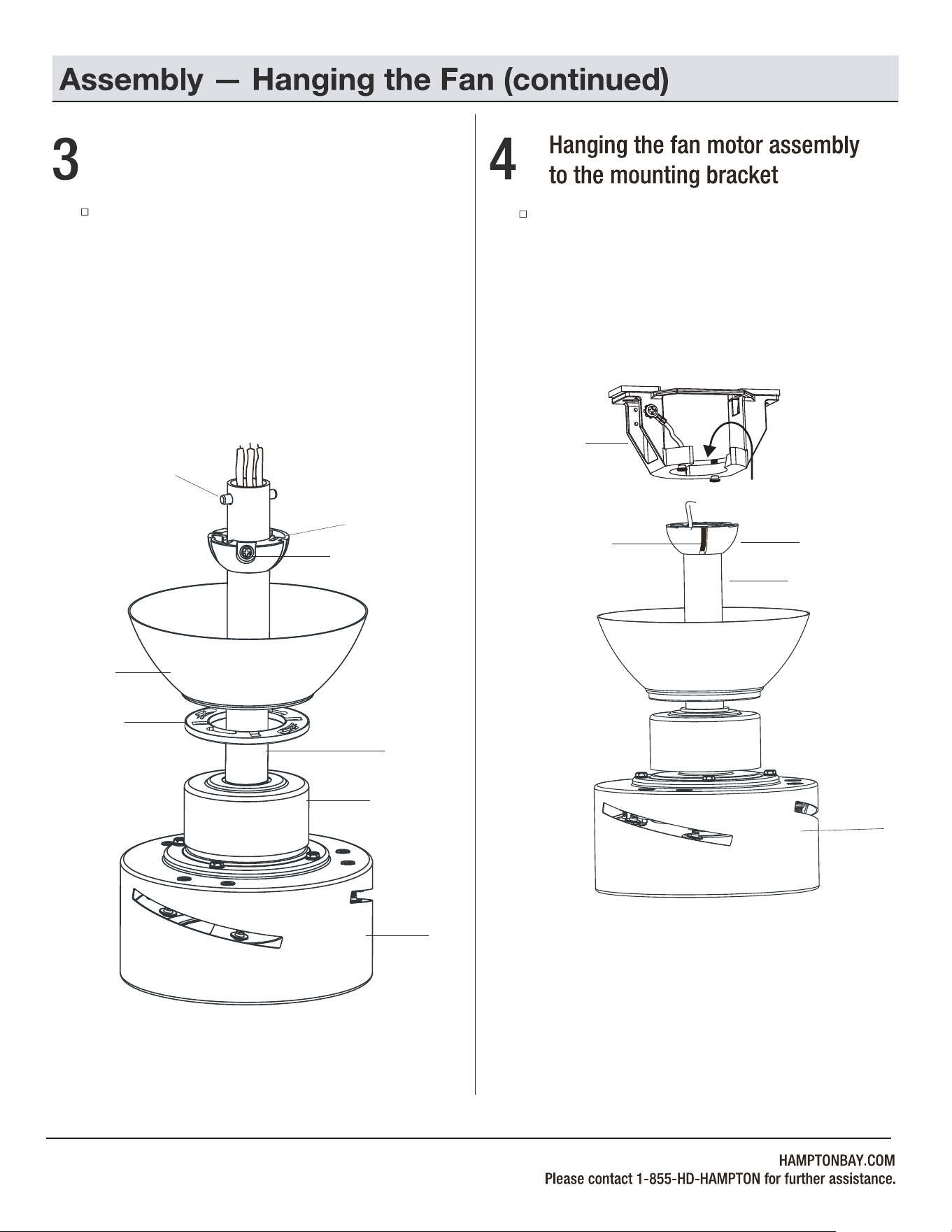
Lift the fan motor assembly (H) into position, and place
the hanger ball (E) into the mounting bracket (B). Rotate
the downrod (F) until the check groove drops into the
registration slot (OO) and seats firmly. The downrod (F)
should not rotate if this is done correctly.
9
FF
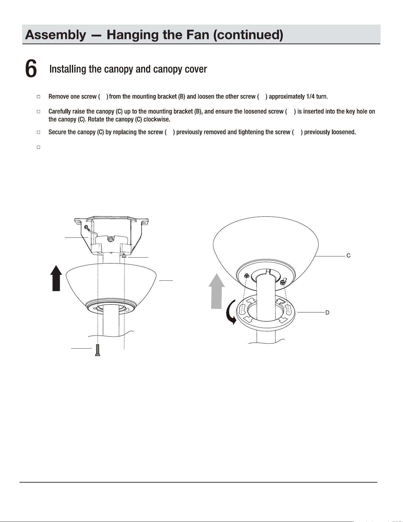
Attaching the coupling cover, canopy
cover, and canopy to the downrod
Slip the coupling cover (G), canopy cover (D) and
canopy (C) onto the downrod (F). Carefully reinstall the
hanger ball (E) onto the downrod (F), and ensure that the
cross pin (FF) is in the correct position, the set screw (II)
is tight, and the wires are not twisted.
II
F
NOTE:
Extension lead wire (N) is available when your
fan installed with a longer downrod.
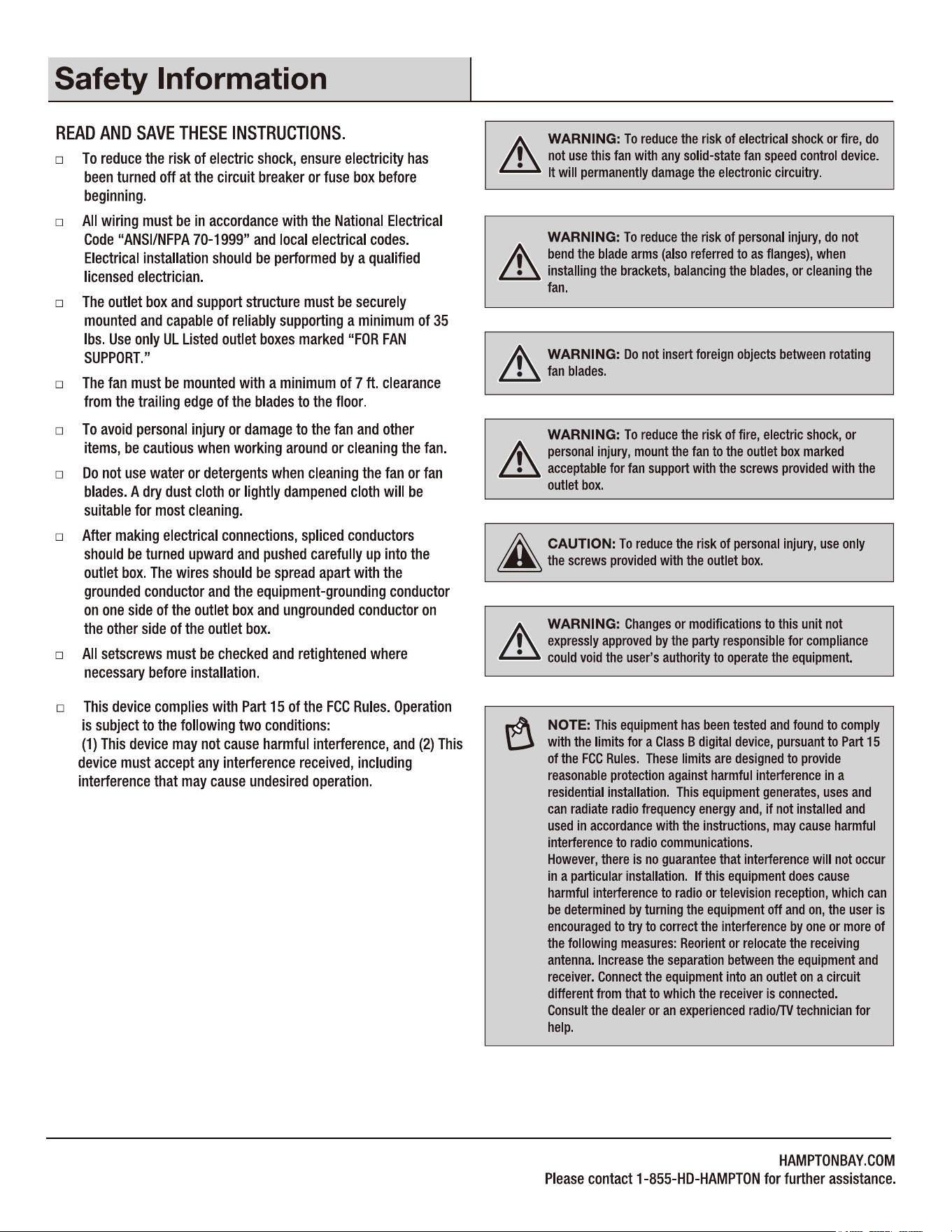
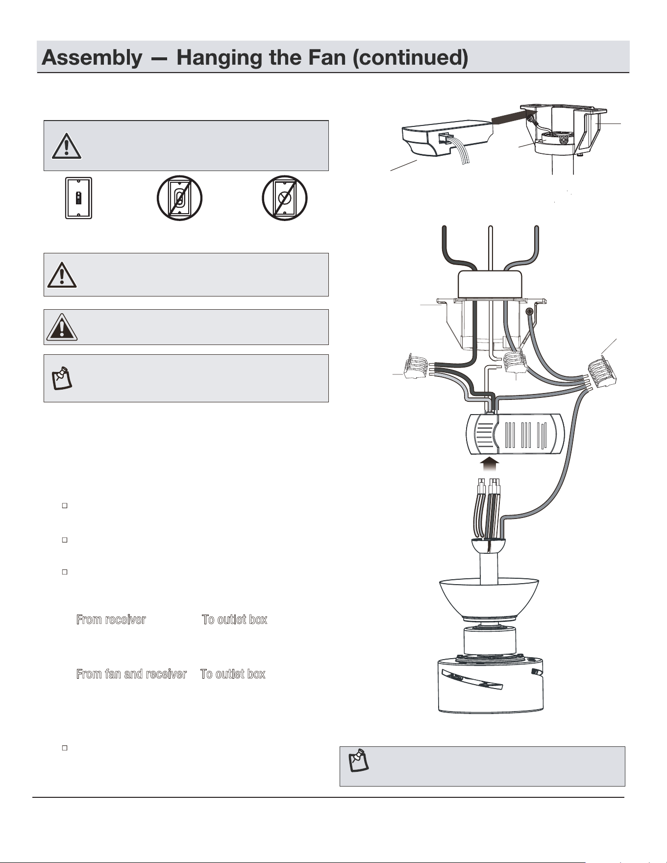
WARNING: Do NOT install this fan with variable speed wall
control or wall-mounted dimmer switch. It may permanently
damage the fan's remote control and cause the fan's
function to fail.
ON / OFF switch NO Variable
speed wall control
NO Dimmer switch
Making the electrical connections
NOTE: The fan must be installed at a maximum distance of
20 ft. from the remote control for proper signal transmission
between the remote control and the fan's receiving unit.
WARNING: Check to see that all connections are tight,
including ground, and that no bare wire is visible at the wire
nuts (except for the ground wire).
If you feel you do not have enough electrical wiring knowledge
or experience, have your fan installed by a licensed electrician.
Follow the steps below to connect the fan to your household
wiring. Use the quick connectors with your fan.
Make sure there are no loose strands or connections.
Insert the receiver (L) into the mounting bracket (B) with
the flat side of the receiver (L) facing the ceiling.
Plug one lead wire of light (with 2P connector) and one
lead wire of fan (with 3P connector) into the receiver (L).
Make wire connections from the receiver (L) and fan to the
outlet box as follows, using the 5 Pin quick connector (CC)
for ground wires and 3 Pin quick connector (DD) for others.
From receiver To outlet box
Black "AC IN L (MOTOR)" +
Red wire "AC IN L (LIGHT)" -------- Black wire (Hot)
White wire "AC in N" --------- White wire (Neutral)
From fan and receiver To outlet box
Green/Yellow wires* ---------- Green or bare wire (Ground)
* There are three green/yellow grounding leads: one from the
mounting bracket (B), one from the hanger ball/downrod assembly
and one from the receiver (L).
Turn the quick connectors upward, spreading them apart
so the green/yellow (ground) and white wires will be on one
side of the outlet box and the black wire will be on the other
side. Carefully tuck the connections up into the outlet box.
CAUTION: To reduce the risk of electric shock, this fan must
be installed with an isolating wall control/switch.
5a
10
B
White
Black
Black
Black
Ground
White
conductor
Green/yellow
Green/yellow
Green/yellow
Outlet Box
Red
DD
DD
CC
B
L
E
DD
DD
DD
DD
DD
CC
CC
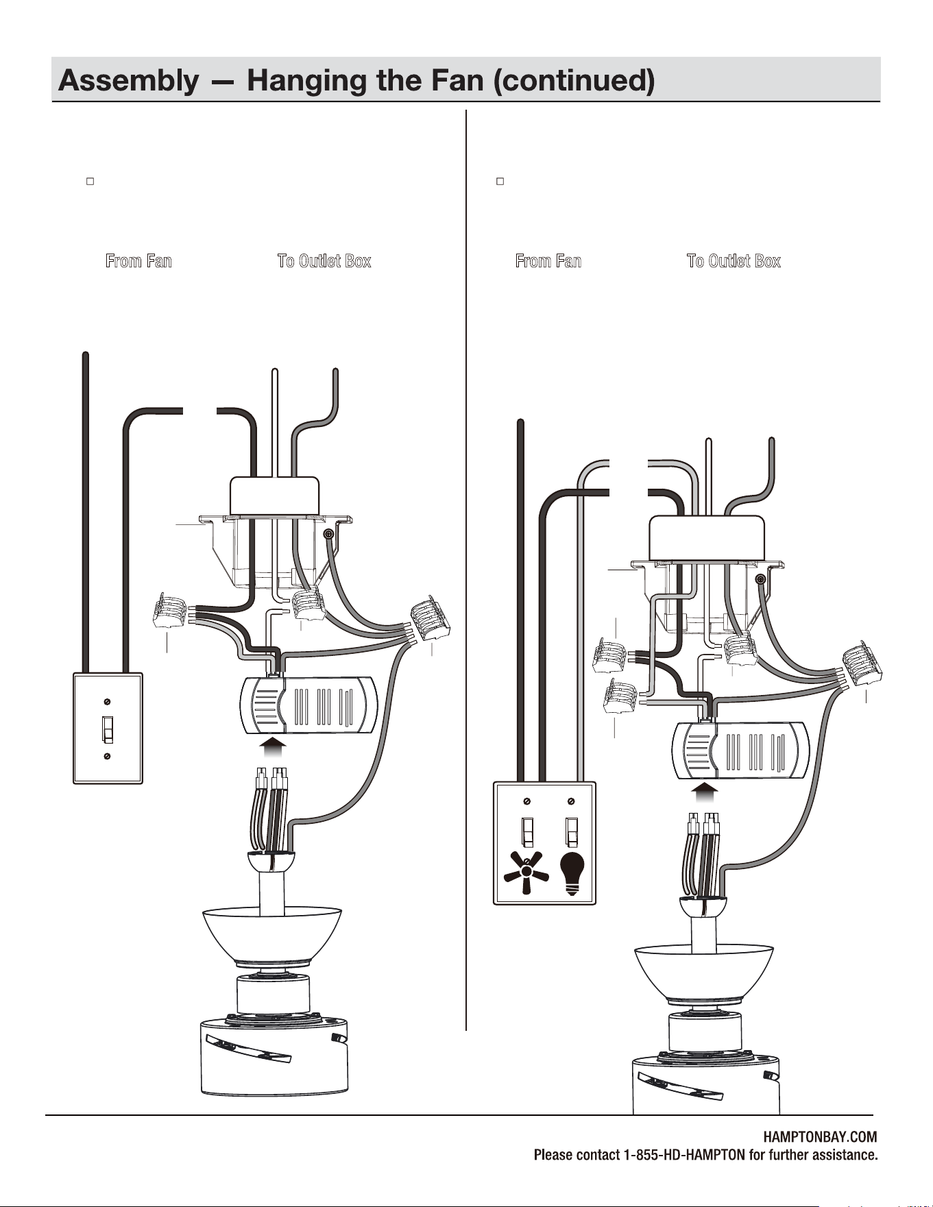
Single Switch Connections
5b
Dual Switch Connections
5c
On a single switch the fan and light can be turned on or off
together. Make wire connections as follows, using the 5 Pin
quick connector (CC) for ground wires and 3 Pin quick
connector (DD) for others.
Wall switch not included.
From Fan To Outlet Box
Black + Red Wires ---------- Black Wire (Hot)
White Wire ------------------- White Wire (Neutral)
Green/Yellow Wires*
------------
Green or Bare Wire (Ground)
On a dual switch the fan and light can be turned on or off
separately. Make wire connections as follows, using the 5 Pin
quick connector (CC) for ground wires and 3 Pin quick
connector (DD) for others.
Wall switch not included.
From Fan To Outlet Box
Black Wire (for Fan) --------- Black Wire (Hot #1)
Red Wire (for Light) --------- Red Wire (Hot #2 but may
be in a color other than black,
white or green)
White Wire ------------------- White Wire (Neutral)
Green/Yellow Wires*
-----------
Green or Bare Wire (Ground)
11
AC IN
Black
Ground
conductorWhite
SINGLE SWITCH
Red
AC IN
Ground
conductor
White
DUAL SWITCH
Black
Outlet Box
Outlet Box
B
White
Black
Black
Green/yellow
Green/yellow
Green/yellow
Red
B
White
Black
Green/yellow
Green/yellow
Green/yellow
Red
CC
CC
CCCC
CC
12
Place the canopy cover (D) on the canopy (C), and rotate the canopy cover (D) clockwise until it locks into position.
C
CC
CC
B
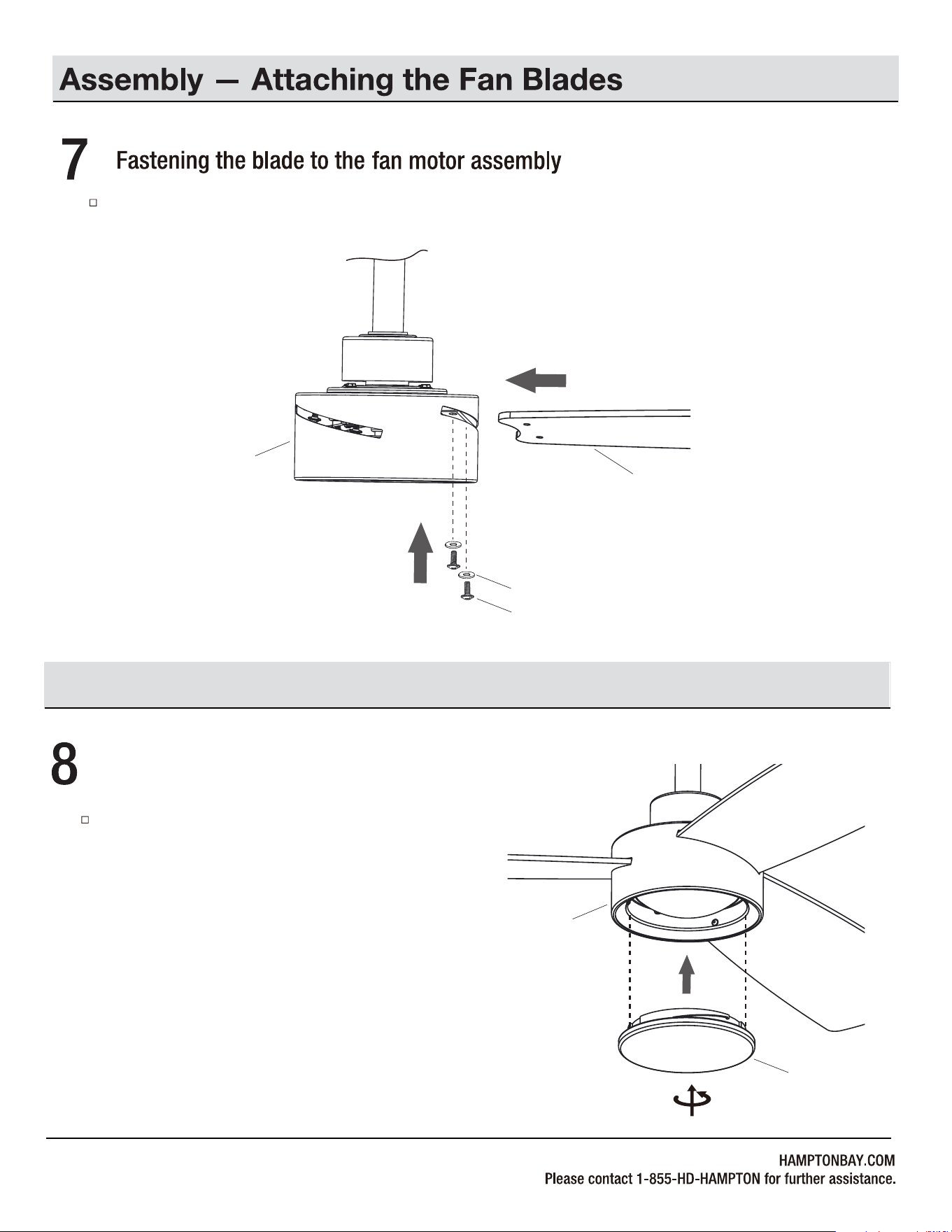
Fasten the blade (A) to the fan motor assembly (H) using the blade screws (AA) and fiber washers (BB).
13
H
BB
A
Attach the light shade (I) to the fan motor assembly (H)
by twisting tightly.
I
H
Assembly — Attaching the Light Shade
AA
Fastening the light shade to the fan motor assembly
14
1
+
0
SETTING UP THE TRANSMITTER
Operation
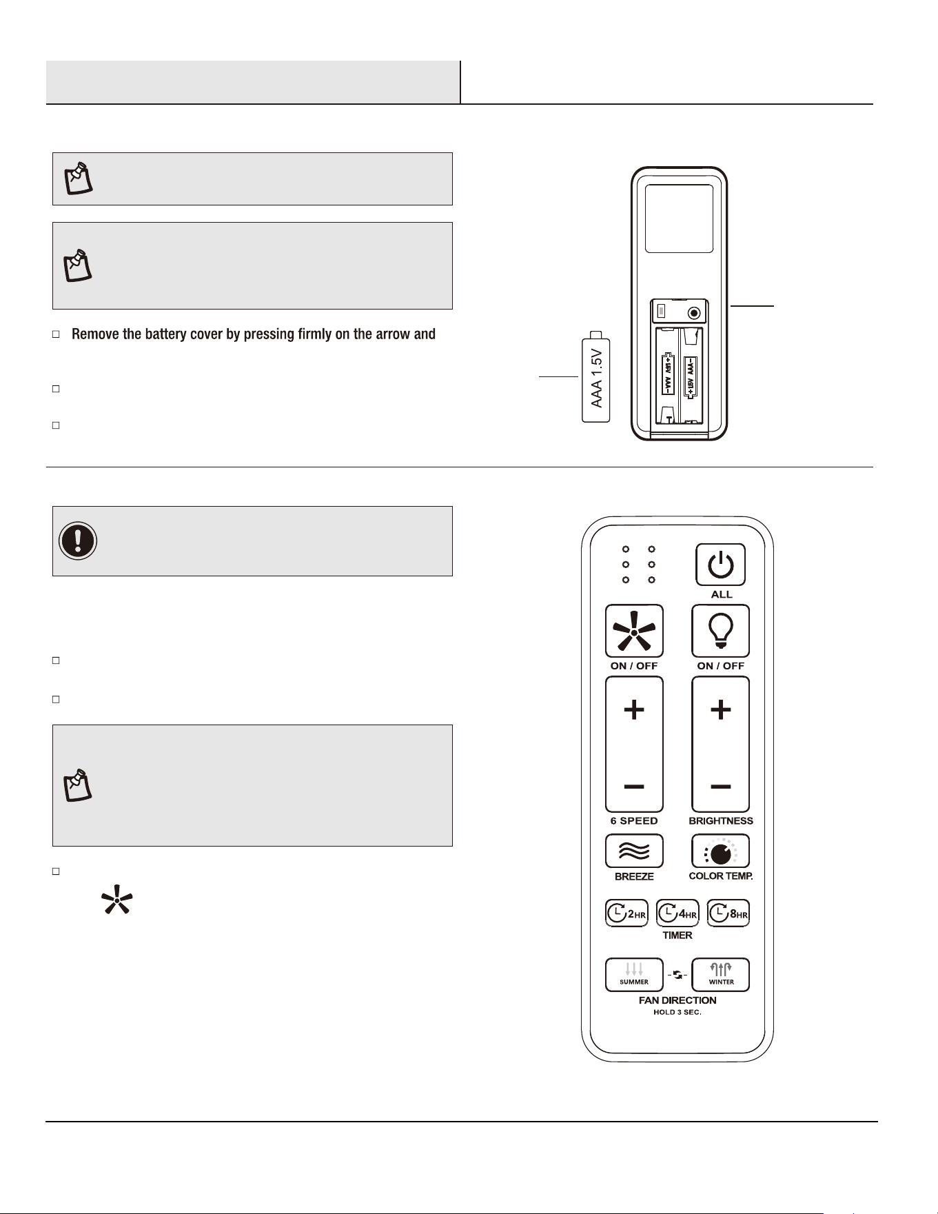
NOTE: Batteries will weaken with age and should be replaced
before leaking takes place as this will damage the remote
control. Dispose of used batteries properly and keep them out
of the reach of children.
PAIRING PROCESS
sliding the cover off.
Install two 1.5V AAA batteries (M) (included).
Replace the battery cover on the remote control (J).
NOTE: If installing multiple fans on separate remotes, only
the fan being programmed should have AC power turned ON.
All other fans, even if they have already been programmed,
should have AC power OFF so they do not memorize other
remotes during the learning process. Separate the fan power
switches by approximately 2 meters.
Within 30 seconds of turning AC power on, press and hold
the " " button for over 5 seconds. Once the receiver has
detected the frequency, the light will blink two times and the fan
blades will start to spin.
Ensure AC power to the fan is OFF to begin the learning process.
Turn the fan’s AC power ON.
To add a remote to your fan’s memory, use the steps below:
NOTE: The remote has been pre-paired in the factory for your
convenience.
IMPORTANT: If you have two or more fans, please follow
steps below to control each fan independently. Also follow
steps below to re-pair the remote and the receiver when needed.
J
M
15
Operation (continued)
OPERATING YOUR FAN AND REMOTE CONTROL
NOTE: The fan will store the last used speed setting for the next time it is turned on.
Correlated Color Temperature (CCT) changing.
Push and release the button to cycle through the five color
temperature options.
Option 1: 2700K (Warm White).
Option 2: 3000K (Soft White).
Option 3: 3500K (Neutral White).
NOTE: On each start up of your ceiling fan, the fan blades will oscillate back and forth. This is a NORMAL OPERATION for DC motor ceiling
fans as they go through a calibration cycle. The fan is NOT DEFECTIVE.
Pressing the button will activate the Comfort Breeze
TM
mode.
If you are using Comfort Breeze
TM
mode, pressing the button
or the fan speed buttons will cancel Comfort Breeze mode
and resume normal fan operation. If you are using Comfort
Breeze mode, press or hold the button three seconds will
also cancel Comfort Breeze mode.
TM
Pressing the timer button will automatically turn fan off
after 2, 4, or 8 hours. To cancel the timer settings, press
and hold the button three seconds and the signal light will
2HR
4
HR
8HR
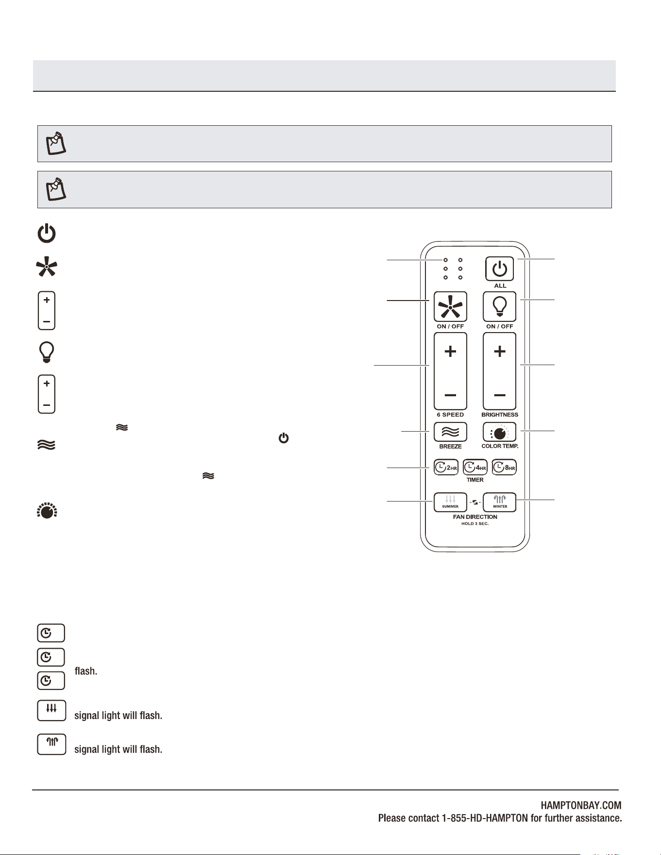
Fan ON/OFF button: Press and release this button to turn the
fan on or off.
Light ON/OFF button: Press and release this button to turn the
light on or off.
Power ALL button: Press and release the power button to turn
the fan and light on or off.
Light BRIGHTNESS button: Press or hold the “+” button to
increase the desired light level. Press or hold the “-” button
to decrease the desired light level.
Fan 6 SPEED button: Press and release the “+” button to
increases the fan speed. Press and release the “-” button to
decreases the fan speed.
Fan on/off
Fan on/
Increases /
decreases
fan speed
Comfort Breeze
TM
Timer
Signal light
Power on/off
Light on/off
Light on/
light dimming
Light color
temperature
Reverse
Forward
Forward, press and hold the button three seconds and the
SUMMER
Reverse, press and hold the button three seconds and the
WINTER
TM
TM
Option 4: 4000K (Bright White).
Option 5: 5000K (Daylight).
16
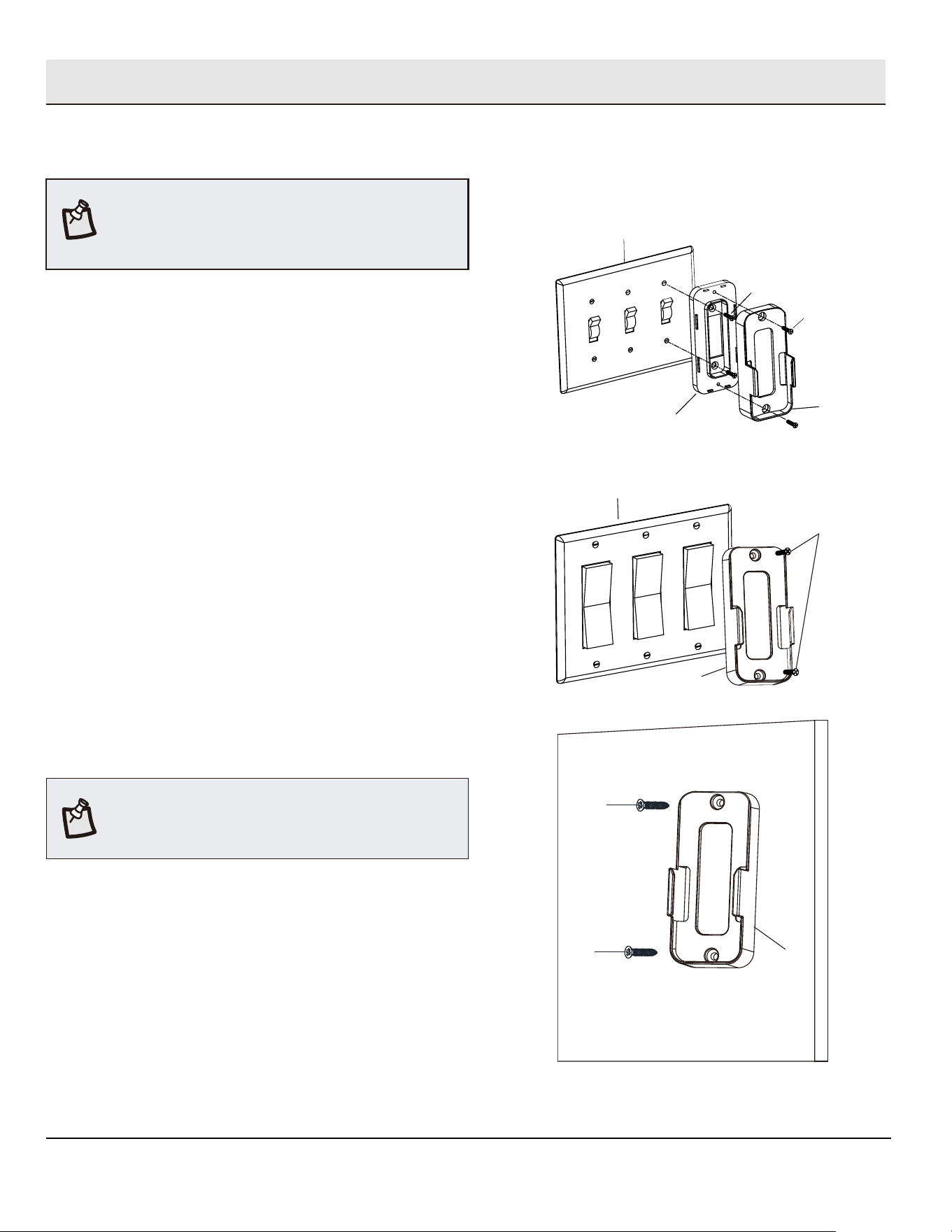
Mounting the remote wall cradle
1a. Attaching over a standard toggle switch
Ƒ
Remove the two screws from the toggle switch face plate.
Ƒ Place the toggle switch spacer over the toggle switch face
plate and align the two large holes of the toggle switch spacer
with the holes in the face plate. Secure the toggle switch
spacer to the face plate using the two included machine
screws (KK).
Ƒ Attach the remote wall cradle (K) to the toggle switch spacer
using the included two short tapered screws (LL). Screw a
short tapered screw (LL) into the top hole and bottom hole of
the wall cradle and into the toggle switch spacer until tight.
Screw wall anchors are included for extra support. The
included screws are designed to screw easily into the wall. If
you would like a more permanent or secure hold, install the wall
anchors prior to attaching the wall cradle to the wall.
NOTE:
1b. Attaching over a paddle switch
Ƒ
Remove the two screws from the paddle switch face plate.
Ƒ Place the remote wall cradle (K) over the paddle switch and align
the two holes of the remote wall cradle (K) with the holes in the
face plate. Secure the remote wall cradle (K) to the face plate
using the two included machine screws (KK).
1c. Attaching to the wall
Ƒ
Position the remote wall cradle (K) in the desired position
and attach to the wall using the included two long tapered
screws (MM).
The remote wall cradle is designed to allow you to
access an existing switch. The remote wall cradle can be
mounted on the wall or to the face plate of a standard toggle
switch or a paddle switch. Follow the instructions below for the
option that best suits your needs.
NOTE:
MM
K
MM
Toggle switch spacer
Toggle switch face plate
LL
KK
K
KK
Paddle switch face plate
K
Operation (continued)
17
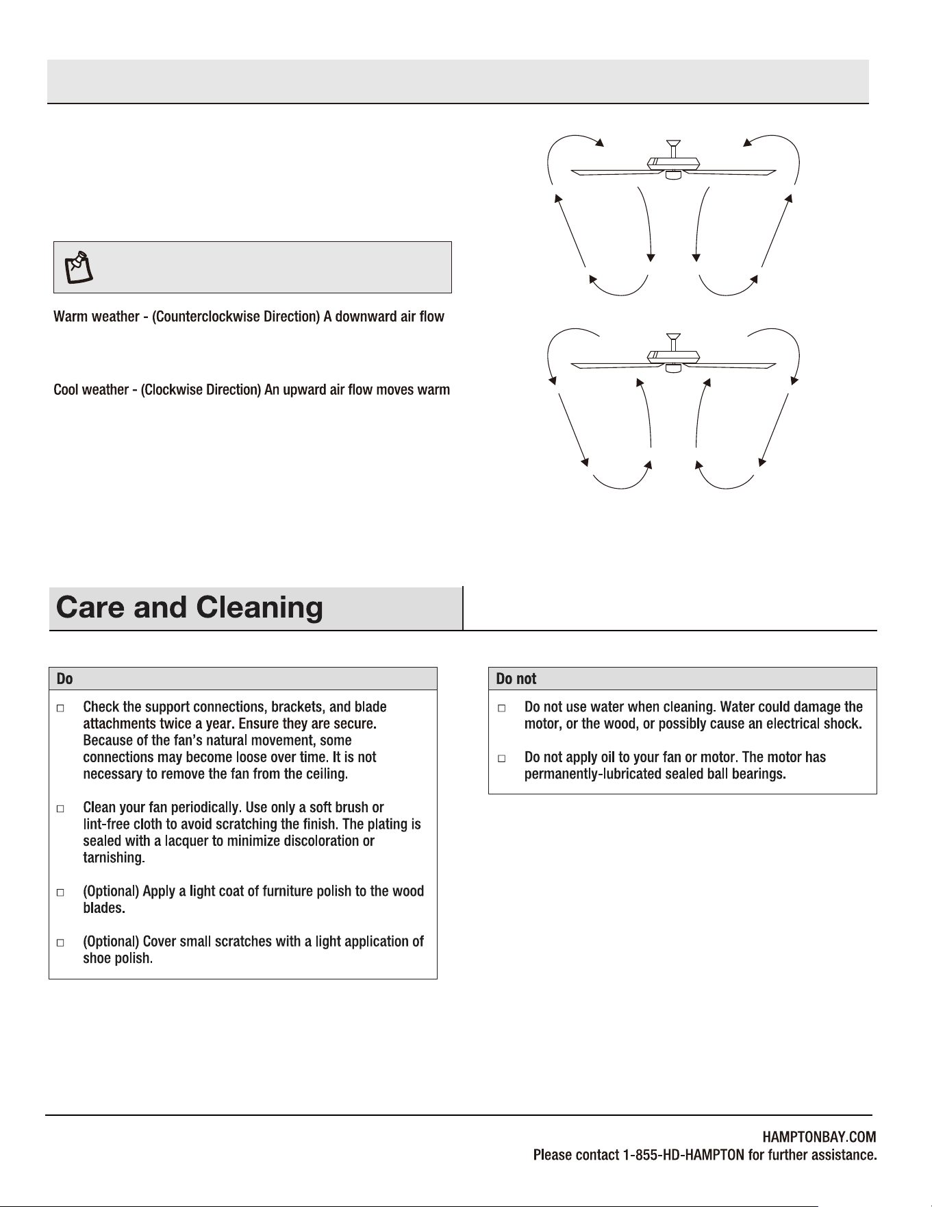
WARM/COOL WEATHER OPERATING
INSTRUCTIONS
NOTE: The fan reverse buttons must be pressed while the
fan is running.
Speed settings for warm or cool weather depend on factors such as
the room size, ceiling height, numbers of fans.
creates a cooling effect. This allows you to set your air conditioner
on a warmer setting without affecting your comfort.
air off the ceiling. This allows you to set your heating unit on a cooler
setting without affecting your comfort.
Operation (continued)
18
Make sure the frequency switches are set correctly.
Do not connect the fan with wall mounted variable speed control(s).
Make sure the frequency switches are set correctly.
Reset the transmitter by going through the transmitter "PAIRING PROCESS".
Fan moves backwards and
forwards when turned on.
This is normal start-up procedure for DC motor fans. The partial movement during start-up is the result
of the DC motor aligning the internal magnetic poles for proper motor operation. This design saves
electricity and allows the fan to operate much quieter than standard AC motor fans.
10
Part
Description
Quantity
LL
K
N
L
Remote control
Remote control wall cradle with toggle
switch spacer included
Receiver
M
1.5V AAA battery
3
Light Shade
Extension power cord use for longer
downrod(longer downrod not included)
19
Fiber washer
Blade screw (3/16 in. x 12 mm)
5 Pin Quick Connector
3 Pin Quick Connector
Mounting bracket screw (preassembled)
Cross pin (not to scale) (preassembled)
Hitch pin (preassembled)
Lock pin (not to scale) (preassembled)
Hanger ball set screw (preassembled)
Fan motor assembly coupling set screw
(preassembled)
AA
BB
CC
DD
EE
FF
GG
HH
II
JJ
KK
LL
MM
1
3
2
1
1
1
1
2
2
2
2
Machine screw
Short tapered screw
Long tapered screw
1
MM
A
B
C
D
E
F
G
H
I
J
K
M
N
L
2
7
7
EE
DD
CC
FF
GG
AA
BB
NN
NN
1Balance kit (not to scale)

X4722
FANXION LLC
5900 BALCONES DRIVE, STE100 AUSTIN, TX, 78731
Tel. 512-387-8855