240-3604
Owner's Manual
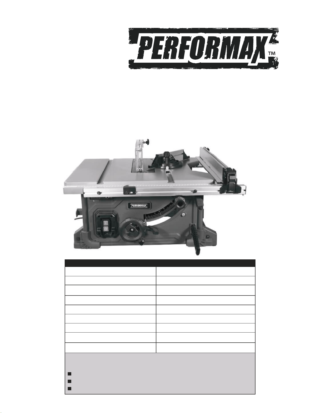
Voltage 120 VOLTS AC, 60Hz
Current rating 13Amps
Blade Speed 5000 RPM (No-Load Speed)
Blade Diameter 8-1/4” carbide tipped
Arbor Size 5/8"
Blade Bevel 0° - 45°
Maximum Cut Depth @ 90 Deg 2-3/4”
Maximum Cut Depth @ 45 Deg 1-3/4”
Max. Right Side Rip Capacity 24-1/2”
Need Assistance ?
Call us on our toll free customer support line : 1-866-915-8626
Technical questions
Replacement parts
Parts missing from package
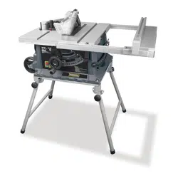
PRODUCT SPECIFICATIONS
8-1/4"
PORTABLE TABLE SAW
Owner's
M

2
Caution! Wear ear protection. The impact of noise can cause damage to hearing.
Caution! Wear safety goggles. Sparks, splinters, chips and/or dust generated while working, can
cause loss of sight.
Caution! Wear a breathing mask. Dust, which can be generated when working on wood and other
materials, can be injurious to health. Never use the device to work on any materials containing
asbestos!
3
f) If operating a power tool in a damp location
is unavoidable, use a residual current operated
protective device protected supply. Use of a
residual current operated protective device reduces
the risk of electric shock.
b) Avoid body contact with grounded surfaces
such as pipes, radiators, ranges and
refrigerators. There is an increased risk of
electric shock if your body is earthed or grounded.
The term "power tool" in
the warnings refers to your power tool.
caution

4
c) Immediately reattach the guarding system
after completing an operation (such as
rabbeting, dadoing or resawing cuts) which
requires removal of the guard riving knife.
The guard riving knife help to reduce the risk
of injury.
5
f) For the riving knife to work, it must be
engaged in the workpiece. The riving knife
is ineffective when cutting workpieces that
is too short to be engaged with the riving
knife. Under these conditions a kickback
cannot be prevented
150mm(5.9")
50mm(1.9")
2mm (0.8")
6
7
saw blades
saw blade
saw blades
saw blade
saw blade
saw blade
saw blades
saw blades
blade
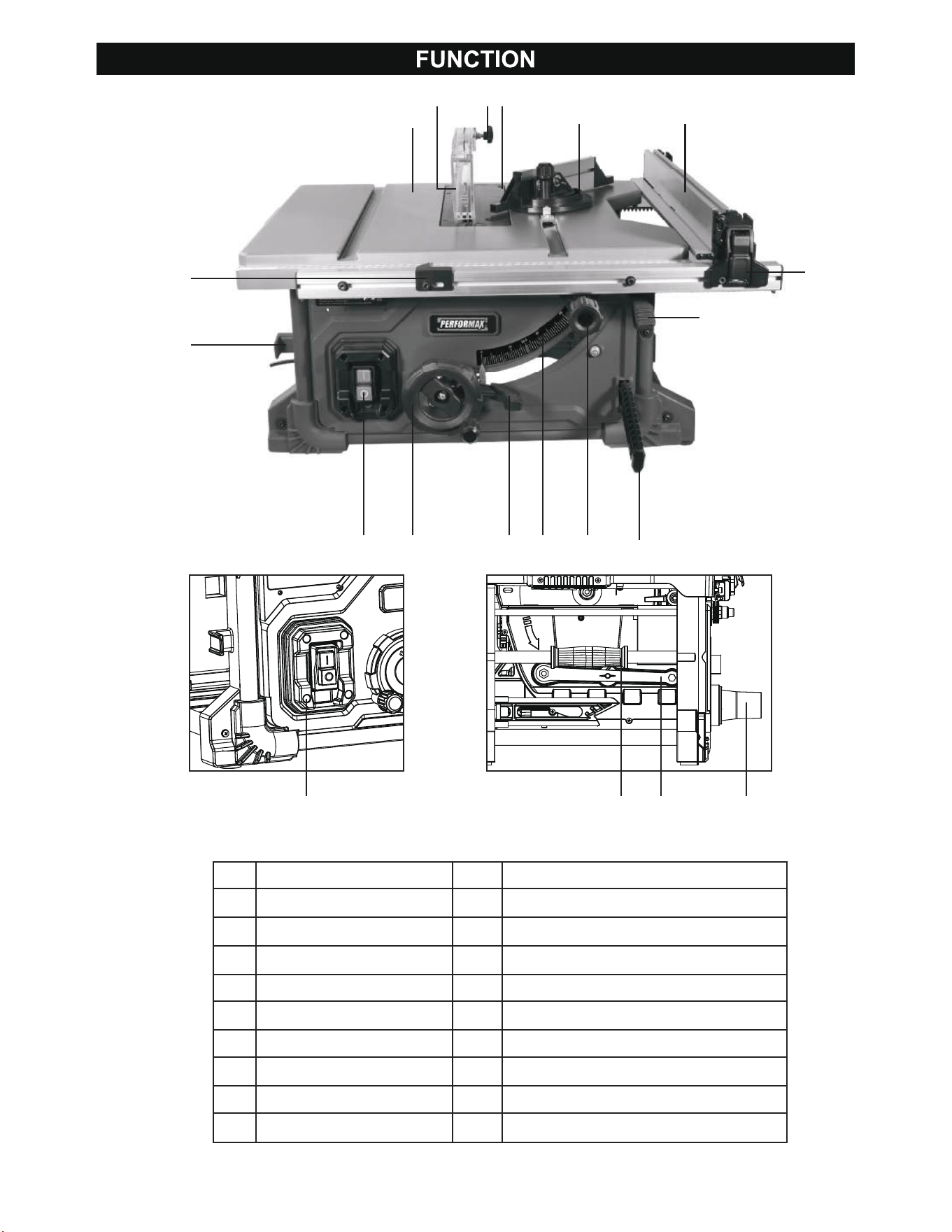
1 Power Switch
2 Cord Storage
3 Miter Gauge
4 Main Table
5 Table Insert
6 Guard Knob
7 Rip Scale
8 Rip Fence
9 Rail Adjustment Knob
10 Rip Fence Lock
11 Blade Height Adjusting Hand-Wheel
12 Bevel Lock Handle
13 Bevel Scale
14 Push Stick
15 Extension Table Lock lever
16 Blade Guard
17 Carry Handle
18 Closed End Wrench
19 Dust Collection Adaptor
20 Power Reset
8
4
16 6 5
3
8
10
15
149131211
20 17 18 19
1
2
7
9
The equipment is to be operated only with
tungsten carbide saw blades. It is prohibited
to use any type of High-speed steel saw
blades.
The bench-type circular saw is designed for the
ripping and cross-cutting (only with the cross stop) .
The equipment is not to be used for cutting any
type of round wood.
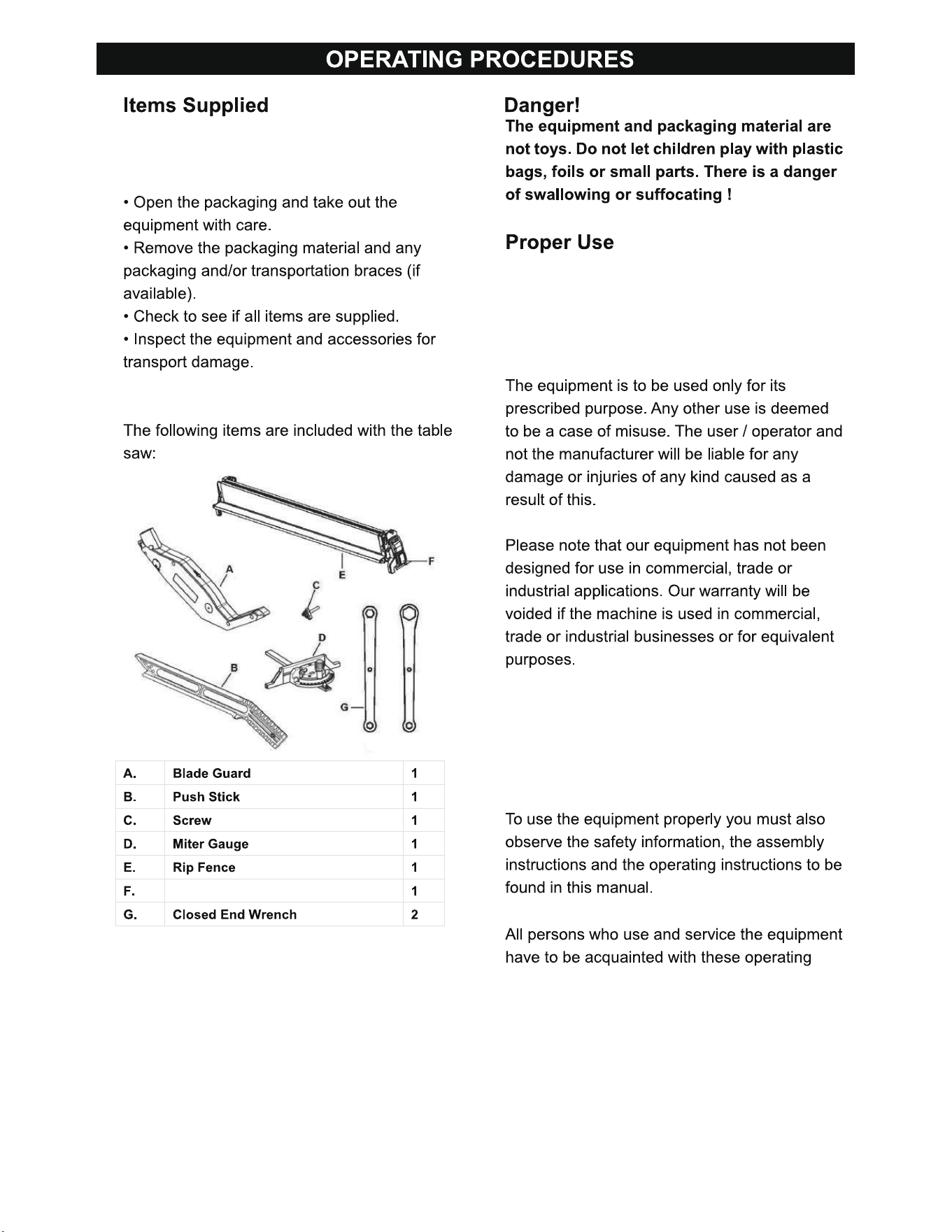
Please check that the saw is complete as
specified in the Function. If parts are missing,
please contact our service center.
Rip Fence Level Locking
10
Ɣ
Only use tool which are in perfect working order.
Ɣ
Service and clean the tool regularly.
Ɣ
Adapt your working style to suit the tool.
Ɣ
Do not overload the appliance.
Ɣ
Have the tool serviced whenever necessary.
Ɣ
Switch the tool off when it is not in use.
Ɣ
Harmful emissions of wood dust.
11
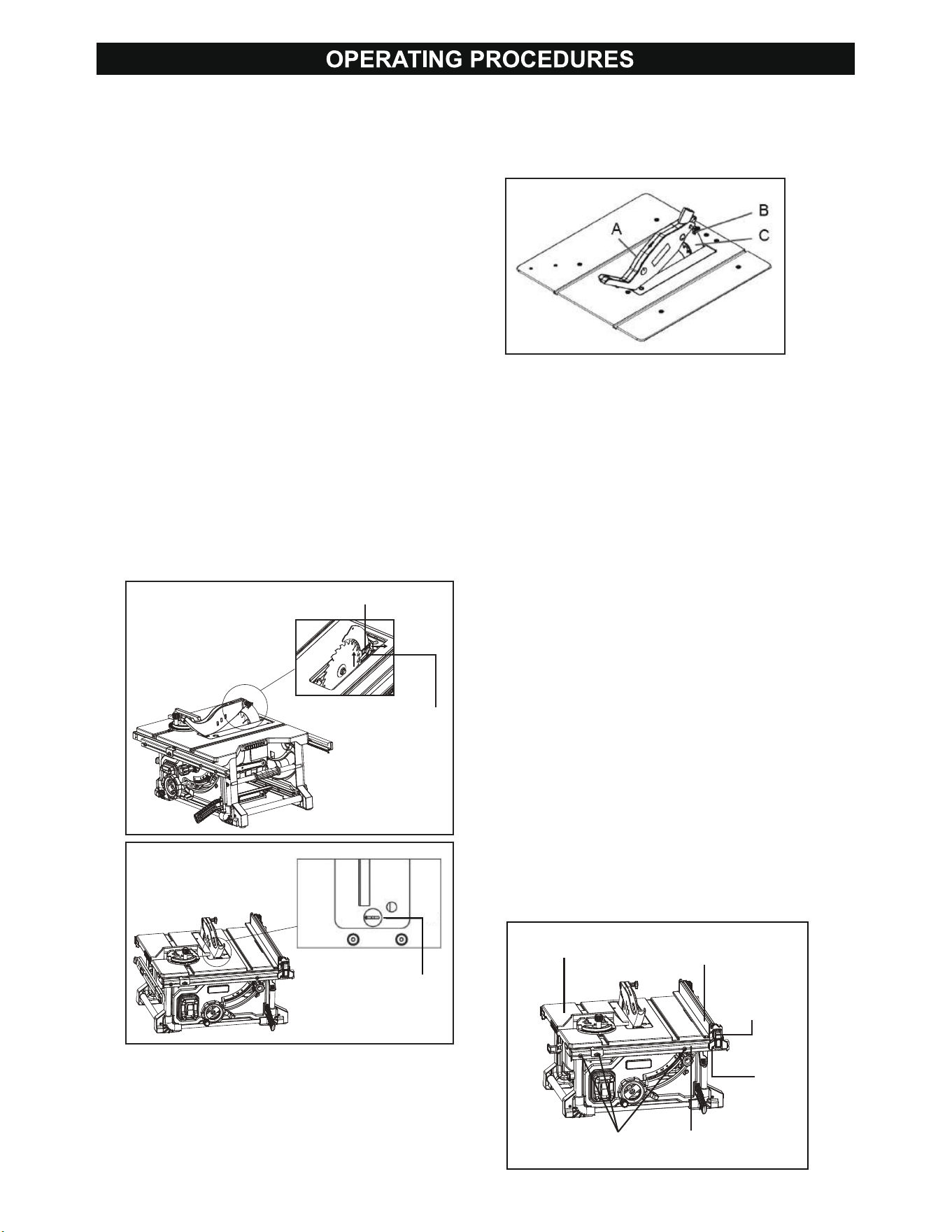
• Mount the saw blade guard(A) together with
the bolt(B) on top of the riving knife(Fig.3.C), so
that the bolt is firmly seated in the hole of the
riving knife(Fig.3.C).
To install the blade guard(Fig.3)
• Install the riving knife(Fig.3.C).
• Install table insert.
• Raise the saw blade by turning the height
adjusting hand-wheel(12 of Page 8) clockwise
(See"To change blade depth").
Install the riving knife(Fig.1)
• Remove the table insert(Fig. 2):
• Lower the blade by turning the height
adjusting hand-wheel(12 of Page 8)
counterclockwise.
• Turn the table insert locking knob clockwise
by Close End Wrench(19 of Page 8) and remove
the table insert.
• Rotate Lock Lever up and pull the Riving Knife
toward right side of the saw to release it from
lock pin. This will allow the knife to slide up and
down.
• Install the riving knife, slide riving knife until it
bottoms out.
• Rotate Lock Lever down to lock the Riving
Knife.
• To reinstall the table insert: Push insert down
in place and turn the insert locking knob
counterclockwise.
NOTE: After installing the riving knife, please
attempt to pull it to ensure it is securely fixed
in place.
Do not screw in the bolt(Fig.3.B) too tightly;
the saw blade guard(Fig.3.A) must move freely.
Dis-assembly is performed in reverse order.
Caution! The saw blade guard(Fig.3.A) must be
lowered onto the workpiece before starting the
sawing operation.
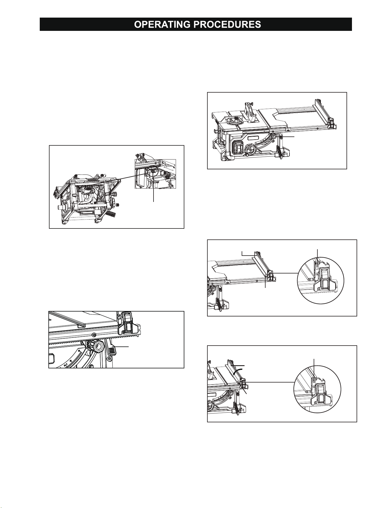
Installing the fip fence(Fig.4)
Note: The Rip Fence can be installed on either side
of blade.
1. Raise Rip Fence Lock Levers on each side of the
Rip Fence.
Note: There are three Screws located on both the
Front & Rear Rails. The Screws will be used to
attach Rip Fence to rails.
2. Align the slot on Rip Fence with the corresponding
screw.
3. Place Rip Fence on the rail so that the slot latches
onto screw and secure Fence to Rails by pushing
Fence Lock Levers down.
WARNING! Make sure Rip Fence is perfectly parallel
to the blade and completely locked in place to
prevent kickback.
INJURY: Do not use Rip Fence when cutting across
wood grain (crosscutting).
Fig.3
Fig.4
Fig.1
Lock Lever
Riving Knife Plywood
Slot
Screw Front Rail
Rip
Fence
Fence
Lock
Lever
Table
Fig.2
Table insert
locking knob
12
NOTE: If the blade is not parallel to the fence,
rotate the adjustment bolt clockwise or
counterclockwise until the blade is parallel to
the horizontal angle gauge(Fig.5).
After adjustment, you can use an angle ruler
to measure whether it is parallel. Secure the
angle ruler to one end of the table, then move
the fence closer to the angle ruler. If the fence
and the angle ruler fit together, it means that
the saw blade and the fence have been
adjusted to be parallel. If there is a gap, it
needs to be readjusted until they fit together.
Extension Table
Note: The Extension Table can be used to support
a workpiece that extends in size beyond the working
table, or for a very narrow workpiece.
1. To support a workpiece that extends beyond the
working table, secure Extension Table to Rip Fence
in the lower position(Fig.8).
2. For work on a narrow workpiece, secure Extension
Table to Rip Fence in the higher position(Fig.9).
Rail Lock Lever(Fig.6)
Note: The Rail Lock Lever allows the user to
adjust the Rip Fence position by moving the
Rail itself.
1. To unlock the Rail Lock Lever, pull lever up
and towards the front of the Saw.
2. To lock, push lever down and towards the
back end of the Saw.
Adjusting Rip Fence(Fig.7)
Note: The Rail Adjustment Knob
(10 of page 8) allows the customer to make
precise adjustments when setting the Rip Fence.
1. Unlock the Rail Lock Lever
2. Slowly turn the Adjusting Knob to fix the Rip
Fence to desired position.
3. Turn the Adjusting Knob clockwise to move
Fence Rail to the right.
4. Turn the Adjusting Knob counter-clockwise to
move Fence Rail to the left.
Fig.5
Fig.6
Fig.7
Adjustment Bolt
Rail lock lever
Rail Driving Knob
Fig.8
Fig.9
Extension Table
Rip Fence
Rip Fence
Low Position
High Position
Extension Table
13
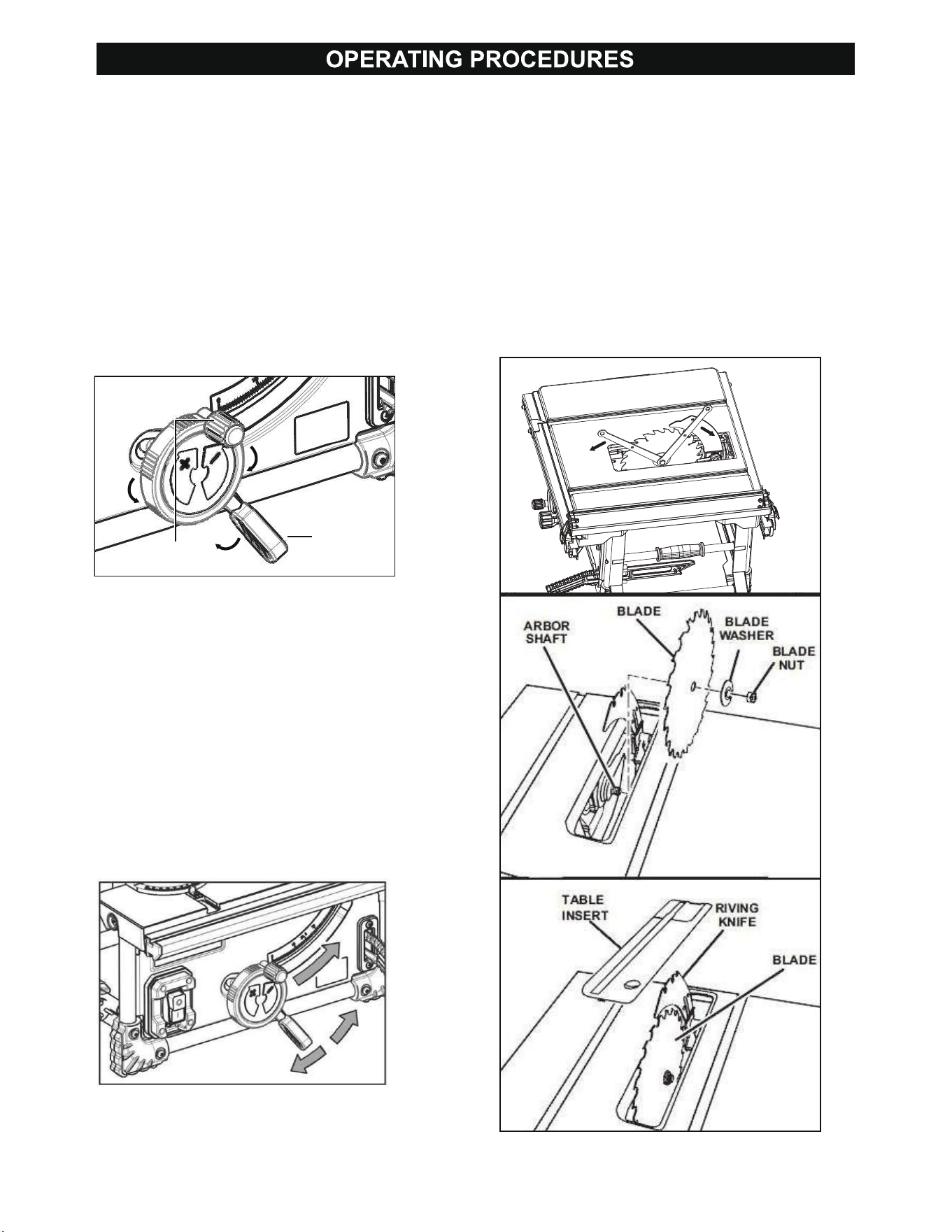
To change blade depth(Fig.10)
The blade depth should be set so that the outer
points of the blade are higher than the
workpiece by approximately 1/8 in. to 1/4 in. but
the lowest points (gullets) are below the top
surface.
1. Turn Bevel Lock Handle clockwise to tighten
it securely.
2. Raise blade by turning Height Adjustment
Knob on the height/bevel adjusting handwheel
clockwise. Lower blade by turning height knob
counterclockwise. Make sure blade is at proper
height.
To change blade angle(Fig.11)
Note: A 90° cut has a 0° bevel and a 45° cut has
a 45° bevel.
1. Loosen the bevel lock handle(13 of page 8)
counter-clockwise.
2. Hold handwheel and slide bevel indicator to the
right to increase angle of blade (bringing blade
closer to 45° from the tabletop).
3. Hold handwheel and slide bevel indicator to the
left to decrease the angle (bringing blade closer
to 90° from the tabletop).
4. Make sure blade is at desired angle. Tighten
Bevel Lock Handle clockwise.
Fig.11
Fig.12
Fig.13
Fig.14
Bevel Lock
Handle
Height
Adjustment Knob
Fig.10
use grinding wheels, wire brushes, or abrasive
wheels on a table saw. Improper saw blade
installation or use of accessories not
recommended may cause serious injury. When
installing the saw blade, wear protective gloves.
Danger of injury when touching the saw blade.
WARNING! Only use a 8-1/4" saw blade with a
5/8" arbor, rated to at least 7,000 RPM and intended
for woodcutting.
To avoid serious injury from an accidental start,
make sure the switch is in the OFF position and
the plug is not connected to the power source
outlet.
Removing and Installing the Blade(Fig.12-14)
WARNING! Make sure that the saw blade is
installed to rotate in the proper direction. Do not
14
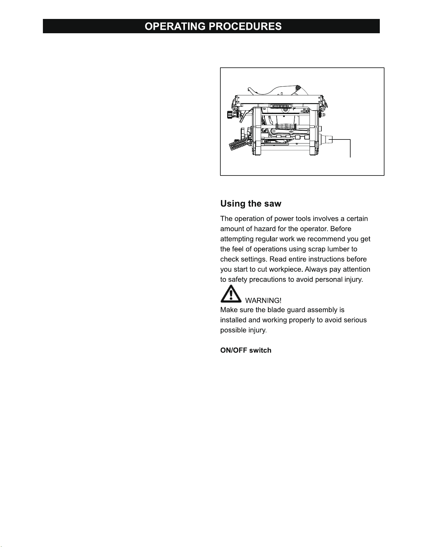
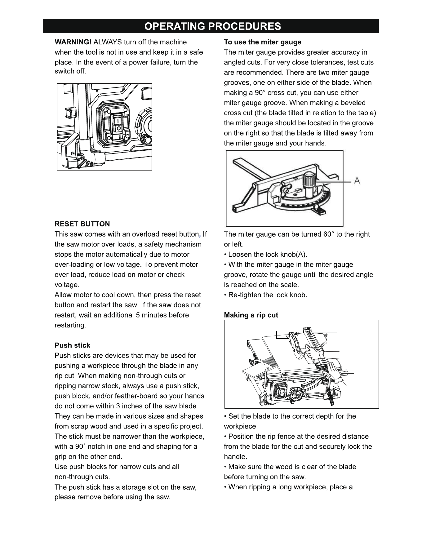
• To turn the saw on, press the green button “I”.
Wait for the blade to reach its maximum speed
of rotation before commencing with the cut.
• To turn the machine off, press the red paddle.
To remove the blade(Fig.12)
1. To remove the blade, unplug saw. Turn Height
Adjustment Knob clockwise to raise blade to
maximum height. Remove Table Insert.
2. Remove the Blade Wrench from storage area.
• Insert the closed-end blade wrench on the blade
washer.
3. Insert the closed-end blade wrench over the
blade nut. Holding both wrenches firmly, pull the
closed end wrench clockwise (right side) while
pulling the closed end wrench counterclockwise
(left side). Remove the nut.
4. Remove Arbor Nut, Outer Blade Flange and
Saw Blade.
Note: All parts must be clean before assembly.
To install the blade
• Insert the inner flange. And place the new
blade on the arbor shaft (the teeth must point
down toward the front of the saw to work
properly).
• Place the outer flange and the blade nut over
the arbor shaft. Be sure all items are snug
against the arbor housing.
• Holding both wrenches firmly, pull the closed
end wrench counterclockwise (right side) while
pulling the closed end wrench clockwise (left side).
Make sure the blade nut is securely tightened.
Do not over-tighten.
• Rotate the blade by hand to make sure it turns
freely.
• Lower the saw blade and reinstall the table insert
and blade guard.
NOTE: To replace the blade with an accessory
blade, follow the instructions provided with the
accessory.
Fig.15
Dust hose adapter
Dust hose adapter(Fig.15)
The saw includes a dust hose adapter, which can
be connected to a vacuum.
15
Fig.16
Fig.17
Fig.18
Scale
Rip Fence
Blade
16
Fig.19
Fig.20
Miter Gauge Angled
Blade angled
Miter Gauge Straight
17
Fig.21
Place Left Hand On Miter
Gauge Here
Always pull out power plug before starting any
cleaning work.
• Clean the equipment regularly by using a moist
cloth with some soft soap. Do not use cleaning
agents or solvents; these could attack the
plastic parts of the equipment. Ensure that no
water can seep into the device. The ingress of
water into an electric tool increases the risk of
an electric shock.
18
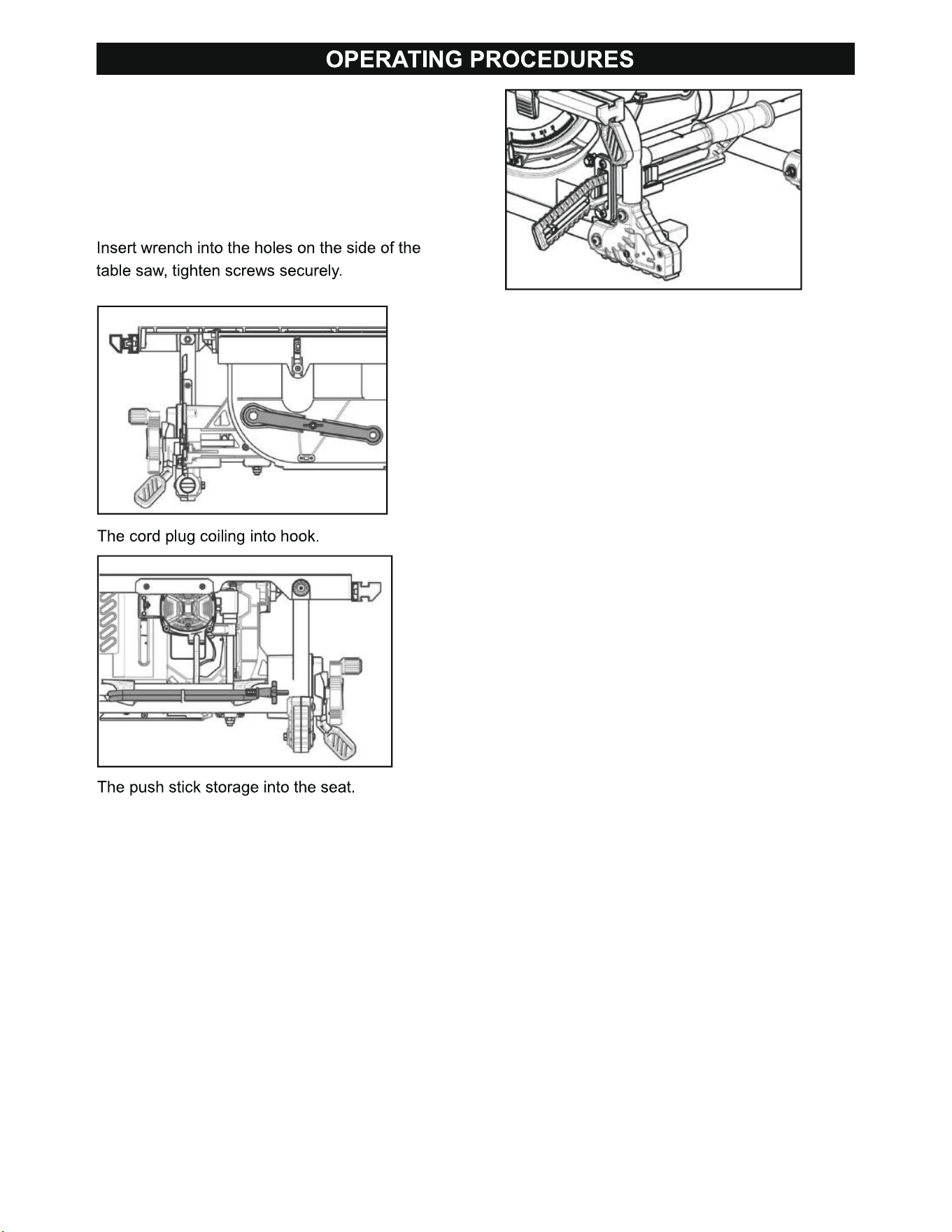
Transportation
This table saw is lightweight and compact, allowing
for easy maneuverability on job sites. Before
moving, please verify that all accessories are
present. The wrench, power cord, and push stick
are stored in designated locations, as indicated
in the following text.
After completion of work, it is recommended to store
the equipment and accessories in a location above
freezing, dark, and dry. The ideal storage
temperature ranges from 5 to 30 °C.
Fig.22
Fig.23
Fig.24

19
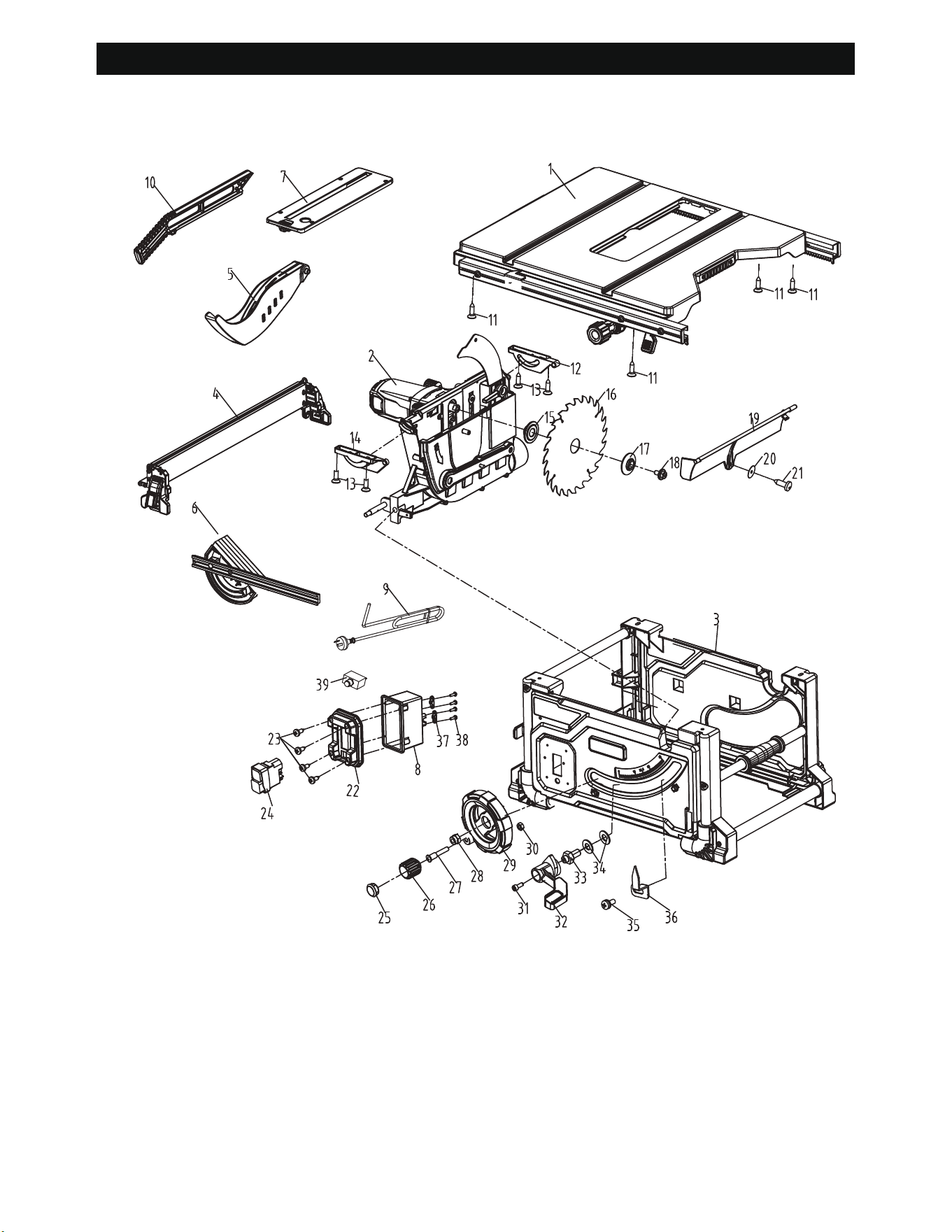
PARTS LIST
No Description Qty
1 Worktable group 1
2 Motor hanger group 1
3 Base group 1
4 Baffle group 1
5 Movable shield group 1
6 Miter gauge 1
7 Slit plate group 1
8 Switch box 1
9 Power cord 1
10 Pushrod 1
11 Sockets 4
12 Rear mount block 1
13 Axis of a screw 4
14 Front mounting block 1
15 Inner flange 1
16 Saw blade 1
17 Outer flange 1
18 Screw 1
19 Lower blade guard 1
20 Washer 1
No Description Qty
21 Self-tapping screws 5
22 Switch baffle 1
23 Switch 1
24 Self-tapping screws 4
25 End cap 1
26 Knob 1
27 Screws 1
28 Lock nut 1
29 Bevel crank wheel 1
30 Lock nut 1
31 Socket screws 1
32 Bevel lock handle 1
33 Screws 1
34 Washer 2
35 Cross head screws 1
36 Bevel indicator 1
37 Crimping plate 1
38 Self-tapping screws 4
39 Overload protector 1
20
ASSEMBLY DRAWING
Exploded Drawing

PARTS LIST
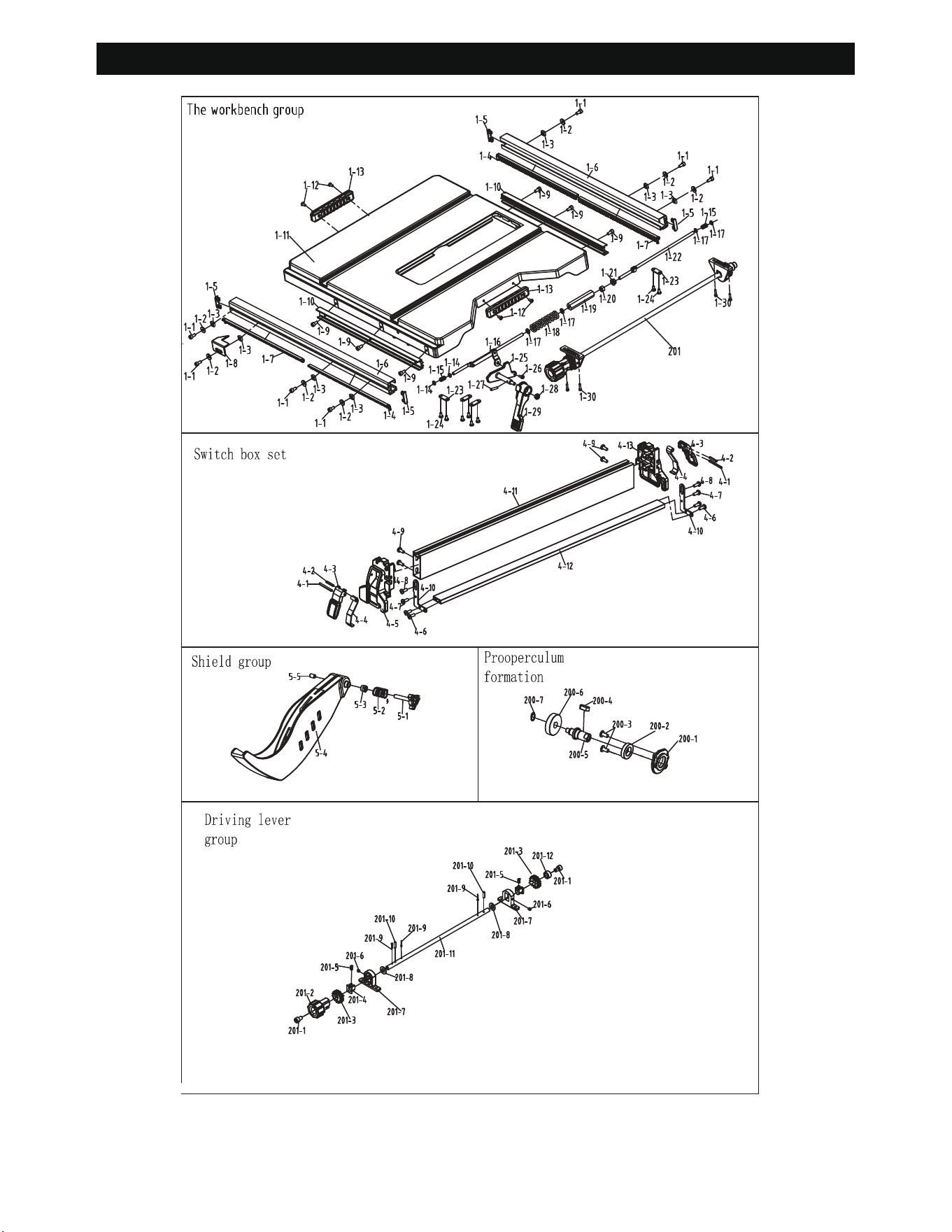
The workbench group
No Description Qty
1-1 Socket screws 7
1-2 Washer 7
1-3 The nut 7
1-4 Extend the rod tooth row (left) 2
1-5 End caps 4
1-6 Extension rod 2
1-7 Extend the rod tooth row (right) 2
1-8 pointer 1
1-9 Socket screws 6
1-10 Slippery course 1
1-11 Table 1
1-12 Cross head screws 4
1-13 Carry handle 2
1-14 gasket 2
1-15 Spring 2
1-16 Front clamping lever set 1
1-17 Washer 4
1-18 Spring 1
1-19 Hex bolt 1
1-20 Hex nut 1
1-21 Hex nut 1
1-22 Rear clamping lever set 1
1-23 Clamp lever clamp plate 4
1-24 Cross head screws 8
1-25 Cam plates 1
1-26 Screw 1
1-27 Pin 1
1-28 Lock nut 1
1-29 Locking handle 1
1-30 Cross head screws 4
1-31 Transmission rod group 1
Switch box set
No Description Qty
4-1 The elastic pin 2
4-2 The elastic pin 2
4-3 The baffle locks the handle 2
4-4 Baffle locking plate 2
4-5 Front of baffle bracket 1
4-6 Cross head screws 4
4-7 Cross head screws 2
4-8 Self-tapping screws 2
4-9 screw 4
4-10 Extension table fixed block 2
4-11 Big baffle 1
4-12 Wing plate 1
4-13 Front of baffle bracket 1
Shield group
No Description Qty
5-1 knob 1
5-2 Spring 1
5-3 Lock nut 1
5-4 Protective cover 1
5-5 Set screw 1
Properculum formation
No Description Qty
200-1 Gear box cover 1
200-2 Bearing 1
200-3 Cross head screws 2
200-4 Arbor 1
200-5 Flat key 1
200-6 Gear 1
200-7 C-ring 1
Properculum formation
No Description Qty
201-1 Sockets 2
201-2 Drive the handwheel 1
201-3 Transmission gear 2
201-4 bushing 2
201-5 Drive rod spring 2
201-6 Glass bead screws 2
Properculum formation
No Description Qty
201-7 Driving block 2
201-8 Washer 2
201-9 Cotter pin 3
201-10 The elastic pin 2
201-11 Transmission rod 1
201-12 lock set of 1
21
ASSEMBLY DRAWING
22

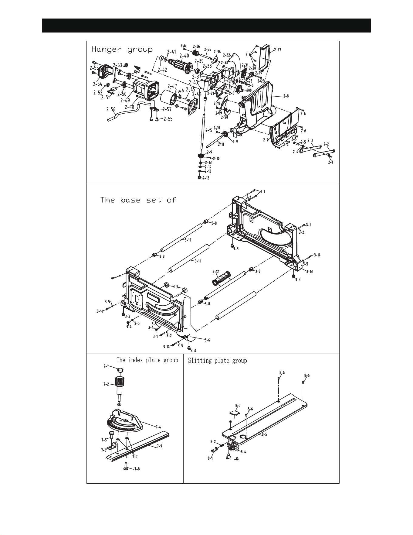
Hanger group
No Description Qty
2-1 Wing-nt 1
2-2 Wrench A 1
2-3 Wrench B 1
2-4 Open card 1
2-5 Carriage bolt 1
2-6 Cross head screws 16
2-7 Saw blade cover 1
2-8 Motor bracket 1
2-9 Gear 2
2-10 Self-tapping screws 2
2-11 Drive shaft 1
2-12 Lock nut 1
2-13 Washer 2
2-14 Rubber mat 1
2-15 Threaded rod 1
2-17 Spacer 1
2-18 Axis of a screw 2
2-19 Washer 1
2-20 Blade guard 1
2-21 Lower blade guard 1
200 Front cover group 1
2-22 bearing 1
2-23 Lock the platen 1
2-24 Cushioning 1
2-25 Slide tabs 1
2-26 Adjust the block 1
2-27 Rear guard 1
2-28 Screws 1
2-29 Spring 1
Hanger group
No Description Qty
2-30 Riving lock lever 1
2-31 Riving knife plywood 1
2-32 Riving knife 1
2-33 Lock nut 1
2-34 Plastic nutterfly nut 1
2-35 Adjustment rod 1
2-36 Adjustment knob 1
2-37 Gear box 1
2-38 O-ring 1
2-39 Bearing 1
2-40 Armture 1
2-41 Bearing 1
2-42 Bearing sleeve 1
2-43 Set screw 2
2-44 Baffle 1
2-45 Self-tapping screws 2
2-46 Washer 2
2-47 Stator 1
2-48 Phillips slotted pan head screws 4
2-49 Motor house 1
2-50 Brush holder 2
2-51 Brush assembly 2
2-52 Spring 2
2-53 Self-tapping screws 4
2-54 Motor end cap 1
2-55 Self-tapping screws 4
2-56 Motor connect wire 1
2-57 Crimping plate 1
PARTS LIST
23

The base set of
No Description Qty
3-1 Self-tapping screws 8
3-2 Washer 8
3-3 Rubber MATS 4
3-4 Screw 2
3-5 Washer 6
3-6 Front panel 1
3-7 Fixed block 1
3-8 Fixed block 1
3-9 Adjust the block 2
3-10 Connecting rods 2
3-11 Connecting rods 2
3-12 Grip 1
3-13 Back panel 1
3-14 Cylindrical head hex socket screws 4
The index plate group
No Description Qty
7-1 End cap 1
7-2 Dial lock knob 1
7-3 Washer 2
7-4 dial 1
7-5 Cross head screws 1
7-6 Index dial pointer 1
7-7 Washer 2
7-8 Cross head screws 1
7-9 Index plate slide bar 1
Slitting plate group
No Description Qty
8-1 Locking block 1
8-2 Spring 1
8-3 Cross head screws 2
8-4 Fixed box 1
8-5 Cutting seam plate 1
8-6 Set screw 4
8-7 keystroke 1
PARTS LIST
24
ASSEMBLY DRAWING
25

26
For questions / comments, technical assistance or repair parts – Please Call Toll
Free at: 1-866-915-8626 (M-F 9am – 5pm).
Distributed by: Menard, Inc., Eau Claire, WI 54703
SAVE YOUR RECEIPTS
THIS WARRANTY IS VOID WITHOUT THEM
8-1/4" PORTABLE TABLE SAW
WARRANTY
TWO-YEAR LIMITED WARRANTY:
If, during normal use, this PERFORMAX™ power tool breaks or fails due to a defect
in material or workmanship within two years from the date of original purchase,
simply bring this tool with the original sales receipt back to your nearest Menards™
retail store. At its discretion, PERFORMAX™ agrees to have the tool or any defective
part(s) repaired or replaced with the same or similar PERFORMAX™ product or part
free of charge, within the stated warranty period, when returned by the original
purchaser with original sales receipt. This warranty; (1) excludes expendable parts;
(2) shall be void if this tool is used for commercial and/or rental purposes; and (3)
does not cover any losses, injuries to persons/property or costs. This warranty does
to state.