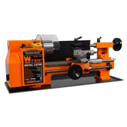
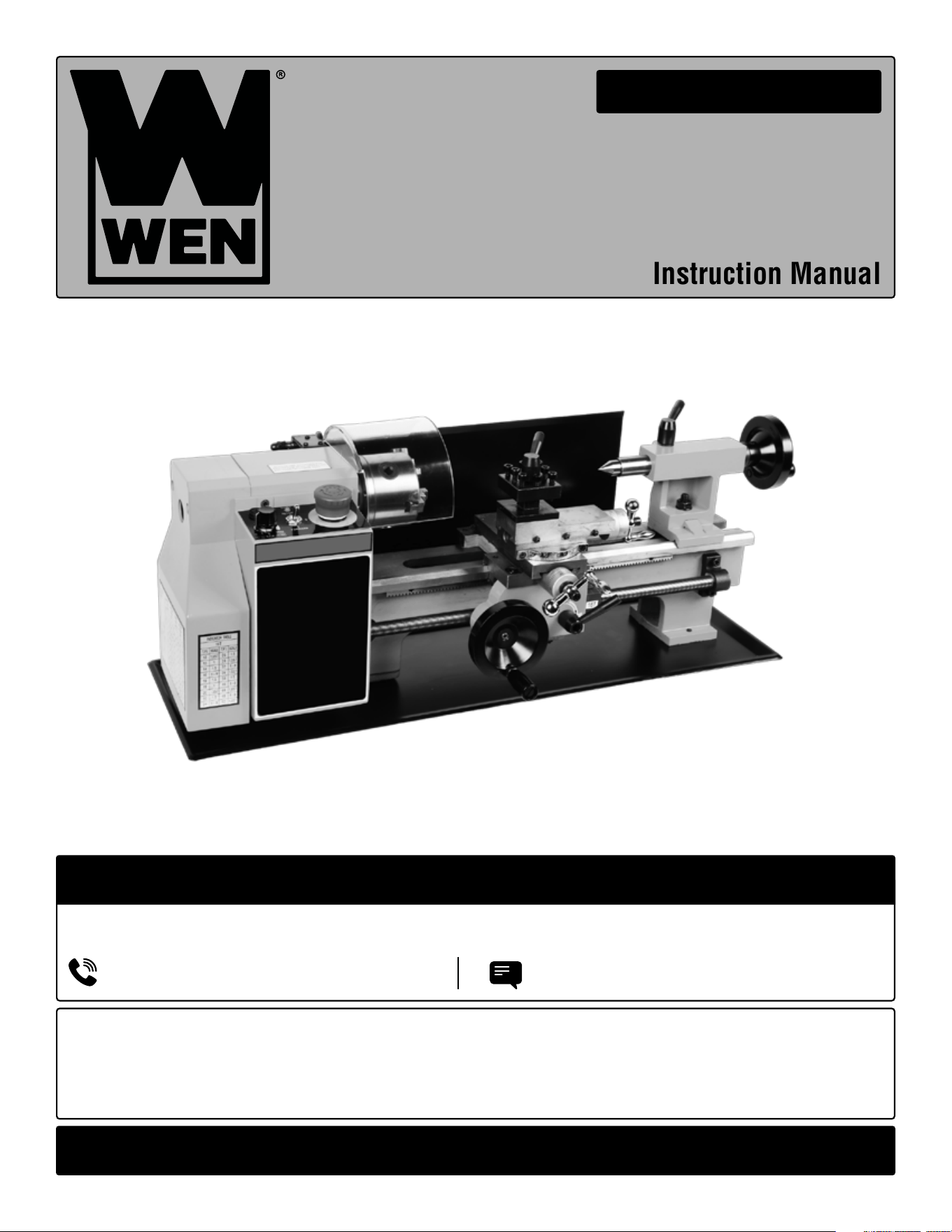
VARIABLE SPEED
BENCHTOP METAL LATHE
Instruction Manual
IMPORTANT: Your new tool has been engineered and manufactured to WEN’s highest standards for dependability,
ease of operation, and operator safety. When properly cared for, this product will supply you years of rugged,
trouble-free performance. Pay close attention to the rules for safe operation, warnings, and cautions. If you use
your tool properly and for its intended purpose, you will enjoy years of safe, reliable service.
NEED HELP? CONTACT US!
Have product questions? Need technical support? Please feel free to contact us:
TECHSUPPOR[email protected]1-847-429-9263 (M-F 8AM-5PM CST)
For replacement parts and the most up-to-date instruction manuals, visit WENPRODUCTS.COM
MODEL ML712, ML716

CONTENTS
WELCOME 3
Introduction ..................................................................................................... 3
Specifications ................................................................................................... 3
SAFETY 4
General Safety Rules ........................................................................................ 4
Metal Lathe Safety Warnings ........................................................................... 6
Electrical Information ....................................................................................... 7
BEFORE OPERATING 8
Know Your Metal Lathe .....................................................................................8
Unpacking & Packing List .............................................................................. 10
Assembly ....................................................................................................... 10
OPERATION & MAINTENANCE 11
Operation ....................................................................................................... 11
Maintenance ....................................................................................................21
Troubleshooting Guide ....................................................................................22
Exploded View & Parts List .............................................................................24
Warranty Statement ........................................................................................32
To purchase accessories and replacement parts for your tool, visit WENPRODUCTS.COM
2
Premium 5/16-Inch Nickel-Plated Indexable Carbide-Tipped Metal Lathe Tool Bits (Model MLA007)
5/8-Inch Keyless Drill Chuck with MT2 Arbor Taper (Model LA162L)
5/8-Inch Keyed Drill Chuck with MT2 Arbor Taper (Model LA164K)

SPECIFICATIONS
INTRODUCTION
Thanks for purchasing the WEN Metal Lathe. We know you are excited to put your tool to work, but first, please
take a moment to read through the manual. Safe operation of this tool requires that you read and understand this
operator’s manual and all the labels affixed to the tool. This manual provides information regarding potential safety
concerns, as well as helpful assembly and operating instructions for your tool.
NOTE: The following safety information is not meant to cover all possible conditions and situations that may occur.
WEN reserves the right to change this product and specifications at any time without prior notice.
At WEN, we are continuously improving our products. If you find that your tool does not exactly match this manual,
please visit wenproducts.com for the most up-to-date manual or contact our customer service at 1-847-429-9263.
Keep this manual available to all users during the entire life of the tool and review it frequently to maximize
safety for both yourself and others.
Indicates danger, warning, or caution. The safety symbols and the explanations with them deserve your
careful attention and understanding. Always follow the safety precautions to reduce the risk of fire, electric shock
or personal injury. However, please note that these instructions and warnings are not substitutes for proper ac-
cident prevention measures.
Model Number ML712, ML716
Motor 110V, 60 Hz, 4A
Output Power 250W
Fuse Glass, 5x20mm, 4A, 250V (F4AL250V)
Chuck 80mm, 3 Jaws
Swing Over Bed 7 Inches (180mm)
Distance Between Centers
ML712: 12 Inches (300mm)
ML716: 16 Inches (400mm)
Spindle Bore 0.8 Inches (20mm)
Cross Slide Travel 2.5 Inches (65mm)
Compound Slide Travel 2.16 Inches (55mm)
Variable Speed 100 - 2500 RPM
Spindle Taper MT3
Tailstock Taper MT2
Minimum Longitudinal Feed Rate 0.004” (0.1mm) per rev.
Maximum Longitudinal Feed Rate 0.008” (0.2mm) per rev.
Screw Threads 12 - 52 TPI (18 Thread Pitches)
Product Weight
ML712: 79.4 Pounds
ML716: 92.6 Pounds
Product Dimensions
ML712: 27-3/4 in. x 11-1/2 in. x 12 in.
ML716: 31 in. x 11-1/2 in. x 12 in.
3

GENERAL SAFETY RULES
WORK AREA SAFETY
1. Keep work area clean and well lit. Cluttered or dark
areas invite accidents.
2. Do not operate power tools in explosive atmo-
spheres, such as in the presence of flammable liquids,
gases or dust. Power tools create sparks which may ig-
nite the dust or fumes.
3. Keep children and bystanders away while operating
a power tool. Distractions can cause you to lose control.
ELECTRICAL SAFETY
1. Power tool plugs must match the outlet. Never mod-
ify the plug in any way. Do not use any adapter plugs
with earthed (grounded) power tools. Unmodified plugs
and matching outlets will reduce risk of electric shock.
2. Avoid body contact with earthed or grounded surfac-
es such as pipes, radiators, ranges and refrigerators.
There is an increased risk of electric shock if your body
is earthed or grounded.
3. Do not expose power tools to rain or wet conditions.
Water entering a power tool will increase the risk of elec-
tric shock.
4. Do not abuse the cord. Never use the cord for car-
rying, pulling or unplugging the power tool. Keep cord
away from heat, oil, sharp edges or moving parts.
Damaged or entangled cords increase the risk of electric
shock.
5. When operating a power tool outdoors, use an ex-
tension cord suitable for outdoor use. Use of a cord
suitable for outdoor use reduces the risk of electric
shock.
6. If operating a power tool in a damp location is un-
avoidable, use a ground fault circuit interrupter (GFCI)
protected supply. Use of a GFCI reduces the risk of elec-
tric shock.
PERSONAL SAFETY
1. Stay alert, watch what you are doing and use com-
mon sense when operating a power tool. Do not use a
power tool while you are tired or under the influence
of drugs, alcohol or medication. A moment of inatten-
tion while operating power tools may result in serious
personal injury.
2. Use personal protective equipment. Always wear
eye protection. Protective equipment such as a respira-
tory mask, non-skid safety shoes and hearing protection
used for appropriate conditions will reduce the risk of
personal injury.
3. Prevent unintentional starting. Ensure the switch is
in the off-position before connecting to power source
and/or battery pack, picking up or carrying the tool.
Carrying power tools with your finger on the switch or
energizing power tools that have the switch on invites
accidents.
4. Remove any adjusting key or wrench before turning
the power tool on. A wrench or a key left attached to a
rotating part of the power tool may result in personal
injury.
5. Do not overreach. Keep proper footing and balance
at all times. This enables better control of the power
tool in unexpected situations.
6. Dress properly. Do not wear loose clothing or jew-
elry. Keep your hair and clothing away from moving
parts. Loose clothes, jewelry or long hair can be caught
in moving parts.
Safety is a combination of common sense, staying alert and knowing how your item works. The term “power tool”
in the warnings refers to your mains-operated (corded) power tool or battery-operated (cordless) power tool.
SAVE THESE SAFETY INSTRUCTIONS.
WARNING! Read all safety warnings and all instructions. Failure to follow the warnings and instructions may
result in electric shock, fire and/or serious injury.
4

GENERAL SAFETY RULES
7. If devices are provided for the connection of dust
extraction and collection facilities, ensure these are
connected and properly used. Use of dust collection
can reduce dust-related hazards.
POWER TOOL USE AND CARE
1. Do not force the power tool. Use the correct power
tool for your application. The correct power tool will
do the job better and safer at the rate for which it was
designed.
2. Do not use the power tool if the switch does not turn
it on and off. Any power tool that cannot be controlled
with the switch is dangerous and must be repaired.
3. Disconnect the plug from the power source and/or
the battery pack from the power tool before making
any adjustments, changing accessories, or storing
power tools. Such preventive safety measures reduce
the risk of starting the power tool accidentally.
4. Store idle power tools out of the reach of children
and do not allow persons unfamiliar with the power
tool or these instructions to operate the power tool.
Power tools are dangerous in the hands of untrained us-
ers.
5. Maintain power tools. Check for misalignment or
binding of moving parts, breakage of parts and any
other condition that may affect the power tool’s opera-
tion. If damaged, have the power tool repaired before
use. Many accidents are caused by poorly maintained
power tools.
6. Keep cutting tools sharp and clean. Properly main-
tained cutting tools with sharp cutting edges are less
likely to bind and are easier to control.
7. Use the power tool, accessories and tool bits, etc.
in accordance with these instructions, taking into ac-
count the working conditions and the work to be per-
formed. Use of the power tool for operations different
from those intended could result in a hazardous situa-
tion.
8. Use clamps to secure your workpiece to a stable
surface. Holding a workpiece by hand or using your
body to support it may lead to loss of control.
9. KEEP GUARDS IN PLACE and in working order.
SERVICE
1. Have your power tool serviced by a qualified repair
person using only identical replacement parts. This
will ensure that the safety of the power tool is main-
tained.
CALIFORNIA PROPOSITION 65 WARNING
Some dust created by power sanding, sawing, grinding,
drilling, and other construction activities may contain
chemicals, including lead, known to the State of Califor-
nia to cause cancer, birth defects, or other reproductive
harm. Wash hands after handling. Some examples of
these chemicals are:
• Lead from lead-based paints.
• Crystalline silica from bricks, cement, and other
masonry products.
• Arsenic and chromium from chemically treated
lumber.
Your risk from these exposures varies depending on
how often you do this type of work. To reduce your ex-
posure to these chemicals, work in a well-ventilated area
with approved safety equipment such as dust masks
specially designed to filter out microscopic particles.
Safety is a combination of common sense, staying alert and knowing how your item works. The term “power tool”
in the warnings refers to your mains-operated (corded) power tool or battery-operated (cordless) power tool.
SAVE THESE SAFETY INSTRUCTIONS.
WARNING! Read all safety warnings and all instructions. Failure to follow the warnings and instructions may
result in electric shock, fire and/or serious injury.
5

METAL LATHE SAFETY WARNINGS
METAL LATHE SAFETY
1. This lathe is designed and intended for use by prop-
erly trained and experienced personnel only. If you are
not familiar with the proper and safe operation of a lathe,
do not use it until proper training and knowledge have
been acquired.
2. Always wear eye protection and a face shield / dust
mask when using the lathe.
3. Make sure all tools, chisels, and accessories are sharp
enough for the task at hand before using them. Always
use the right tool at the correct speed and feed rate.
4. Turn off and unplug the machine before doing any
cleaning or maintenance. Use a brush to remove chips
or debris. Never use your hands to remove excess mate-
rial and debris.
5. Check the workpiece carefully for inconsistencies or
obstructions. These types of blemishes may cause a
safety risk during turning.
6. Rotate the workpiece by hand to check clearance be-
fore turning the machine on.
7. Select the appropriate speed for the task at hand. Start
at a low speed and allow the lathe to ramp up to the
operating speed before engaging any chisels, tools, or
other carving accessories.
8. Never stop a rotating workpiece with your hand.
9. When turning between centers, make sure the head-
stock and tailstock are tight and snug against the work-
piece.
10. Always use a brush or rag to clear away chips from
the workpiece. Using your hand can cause serious injury.
11. Always remove the key from the chuck jaws before
operation.
12. Always wear a full face mask. If a tool or workpiece
breaks off, it can create a hazard to users and onlookers.
13. Always use the right cutting tool. An improper tool
could break or cause unwanted strain on the machine.
14. Never attempt to stop the lathe with your hand. You
will lose your hand.
15. Always use the proper feed rate for your workpiece.
An overly fast feed rate can damage the lathe or the
workpiece.
16. Secure the workpiece properly, make sure the chuck
is tight and secure on the workpiece before beginning
to turn. A loose workpiece can shoot out and severely
injure you or anyone around.
17. Use a tailstock to support long work stock. Anything
more than 2.5 times as long as it is thick needs the tail-
stock to support it.
18. Never operate the lathe with damaged parts.
19. Never turn a workpiece at RPMs that are too high
for the work material. This can cause the cutting tool to
break and launch off, injuring you or a bystander.
20. Never reverse motor direction while the machine is
running.
21. Never change the lead screw feed direction while the
machine is running.
22. Always ensure proper clearance between the work-
piece and the cross slide, compound slide, and tool post.
23. Always disengage automatic feed after a cutting
pass, even if it is the final cut. You can forget and hurt
yourself upon next use.
24. Always tie up long hair. Do not wear any loose /
hanging clothing. Even aprons can be hazards when im-
properly secured.
25. Remove any and all jewelry, rings, watches, etc. to
avoid getting them caught in the lathe.
WARNING! Do not let comfort or familiarity with the product replace strict adherence to product safety rules.
Failure to follow the safety instructions may result in serious personal injury.
6
3. Check with a licensed electrician or service personnel if you do not completely under-
stand the grounding instructions or whether the tool is properly grounded.
4. Use only three-wire extension cords that have three-pronged plugs and outlets that
accept the tool’s plug. Repair or replace a damaged or worn cord immediately.
CAUTION! In all cases, make certain the outlet in question is properly grounded. If you
are not sure, have a licensed electrician check the outlet.
GROUNDING INSTRUCTIONS
In the event of a malfunction or breakdown, grounding provides the path of least resistance for an electric current
and reduces the risk of electric shock. This tool is equipped with an electric cord that has an equipment grounding
conductor and a grounding plug. The plug MUST be plugged into a matching outlet that is properly installed and
grounded in accordance with ALL local codes and ordinances.
1. Do not modify the plug provided. If it will not fit the outlet, have the proper outlet installed by a licensed electri-
cian.
2. Improper connection of the equipment grounding conductor can result in electric shock. The conductor with the
green insulation (with or without yellow stripes) is the equipment grounding conductor. If repair or replacement of
the electric cord or plug is necessary, DO NOT connect the equipment grounding conductor to a live terminal.
1. Examine extension cord before use. Make sure your extension cord is properly wired and in good condition.
Always replace a damaged extension cord or have it repaired by a qualified person before using it.
2. Do not abuse extension cord. Do not pull on cord to disconnect from receptacle; always disconnect by pulling on
plug. Disconnect the extension cord from the receptacle before disconnecting the product from the extension cord.
Protect your extension cords from sharp objects, excessive heat and damp/wet areas.
3. Use a separate electrical circuit for your tool. This circuit must not be less than a 12-gauge wire and should be
protected with a 15A time-delayed fuse. Before connecting the motor to the power line, make sure the switch is in
the OFF position and the electric current is rated the same as the current stamped on the motor nameplate. Running
at a lower voltage will damage the motor.
GUIDELINES AND RECOMMENDATIONS FOR EXTENSION CORDS
When using an extension cord, be sure to use one heavy enough to carry the current your product will draw. An
undersized cord will cause a drop in line voltage resulting in loss of power and overheating. The table below shows
the correct size to be used according to cord length and ampere rating. When in doubt, use a heavier cord. The
smaller the gauge number, the heavier the cord.
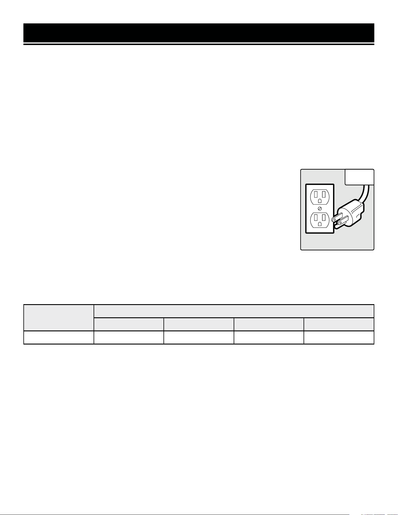
ELECTRICAL INFORMATION
AMPERAGE
REQUIRED GAUGE FOR EXTENSION CODS
25 ft. 50 ft. 100 ft. 150 ft.
4A 18 Gauge 16 Gauge 16 Gauge 14 Gauge
7
Fig. A
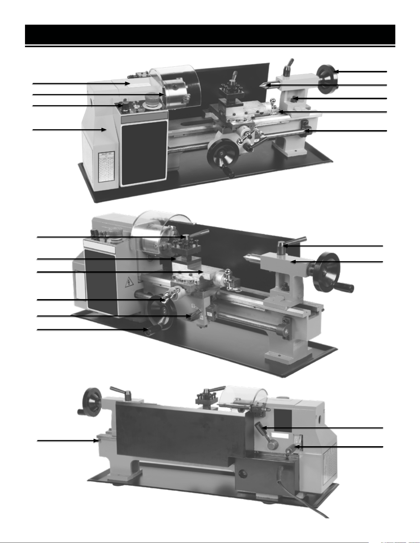
KNOW YOUR METAL LATHE
1
3
4
16
6
7
8
9
17
13
14
15
2
10
12
11
5
18
19
20
8

KNOW YOUR METAL LATHE
21
22
23
24
25
1. Headstock
2. Spindle
3. Lathe Control Panel
4. Gear Train Cover
5. Tailstock Handwheel
6. Quill
7. Tailstock Lock Nut
8. Compound Slide Handle
9. Thread-Cutting Lead Screw
10. Tool Post Lock
11. Tool Post
12. Compound Slide
13. Cross Slide Handle
14. Automatic Feed Lever
15. Manual (Carriage) Feed Lever
16. Quill Lock
17. Tailstock
18. Stop Screw
WARNING! Do not shift from high to low while the lathe is running.
WARNING! Do not change direction of the leadscrew while the lathe is running.
WARNING! Do not change the spindle direction while the unit is running. Changing the spindle direction
during operation will damage the lathe.
19. High / Low Speed Range Lever: Allows the user to shift the spindle speed range from HIGH (0 - 2500 RPM) to
LOW (0 - 1100 RPM).
20. Forward / Neutral / Reverse Lever: Change the direction of the leadscrew rotation between forward, reverse,
and neutral. The handle is spring-loaded; pull it out (away from the lathe’s body), adjust its position, and release.
21. Fuse Cap: Contains the fuse (4A) that protects the unit from circuit overloads. The fuse can be removed by turn-
ing the cap a quarter turn counterclockwise with Phillips-head screwdriver, then pulling fuse and cap out. Replace
the fuse if it is blown with a glass, 5x20mm, 4A, 250V fuse (F4AL250V).
22. Speed Control Knob: Allows the adjustment of the lathe’s spindle speed from 0 to 2500 RPM.
23. Spindle Direction Selector: Allows the user to select the direction of the spindle between clockwise (forward),
neutral (0), and counterclockwise (reverse). Forward = toward operator (clockwise when viewed from the headstock
end); opposite for reverse.
NOTE: When turning the lathe on, you may use the direction selector or variable speed knob first. If the knob is set
to 0 when the direction selector is used, you must increase the speed using the knob before the spindle will start
turning.
24. Fault Light: Illuminates if there is a motor fault, or if the emergency shutoff button is pushed during operation
and is not released before trying to restart.
25. Emergency Shutoff: Stops power to the unit when pressed during operation. Button must be UP (clasp re-
leased) to permit operation. Turn the red button cap clockwise to release it.
9

UNPACKING & PACKING LIST
UNPACKING
With the help of a friend or trustworthy foe, such as one of your in-laws, carefully remove the metal lathe from the
packaging and place it on a sturdy, flat surface. Make sure to take out all contents and accessories. Do not discard
the packaging until everything is removed. Check the packing list below to make sure you have all of the parts and
accessories. If any part is missing or broken, please contact customer service at 1-847-429-9263 (M-F 8-5 CST),
or email [email protected].
1. Metal Lathe ...............................................................1
2. Rubber Feet ...............................................................4
3. M6 Pan Head Screws ................................................4
4. Hex Keys (3mm, 4mm, 5mm, 6mm) ........................4
5. Chuck Key .................................................................1
6. Plastic Oil Container (Oil Not Included) .....................1
7. Spare Fuse ................................................................1
8. Plastic Handles with Nuts and Bolts ..........................1
9. MT2 Dead Center (For Tailstock) ...............................1
10. External Jaws for 3-Jaw Chuck ...............................3
11. 8mm x 10mm Wrench ............................................1
12. 14mm x 17mm Wrench ..........................................1
13. Gear Set ..................................................................1
14. Chip Tray .................................................................1
PACKING LIST
ASSEMBLY
NOTE: Before assembling, carefully wipe off all grease and rust-protectant coating with a soft cloth. Use kerosene or
acetone to fully remove the grease and coating. Apply a light coat of good-quality paste wax to all machined surfaces
to prevent rusting and ensure ease of movement between parts.
Use the four M6x16 pan-head screws to attach the chip tray and rubber feet to the tapped holes in the underside of
the lathe body. Insert the screws through the feet, through the chip tray, and into the lathe. Tighten using Phillips-
head screwdriver (not included). We strongly recommend that to provide maximum stability and safety, users
should secure the lathe to a firm foundation as described under “Mounting the Lathe” below.
Attach the plastic handles to the rims of the manual feed and tailstock feed handwheels. Ensure the nuts are tight
and the handles spin freely about the bolts without excessive end play.
The carriage, cross slide, and compound slide adjustments are all factory-set to ensure smooth movement in both
directions. However the adjustments may have been misaligned during transportation. This will be indicated by stiff
or erratic movement. Refer to “ADJUSTING THE GIBS” on page 20 for adjustment methods.
All hex keys and wrenches necessary to carry out various adjustments are supplied together with a chuck key for
the 3-jaw chuck. The fuse socket (21) is located on the main control panel.
10
OPERATION
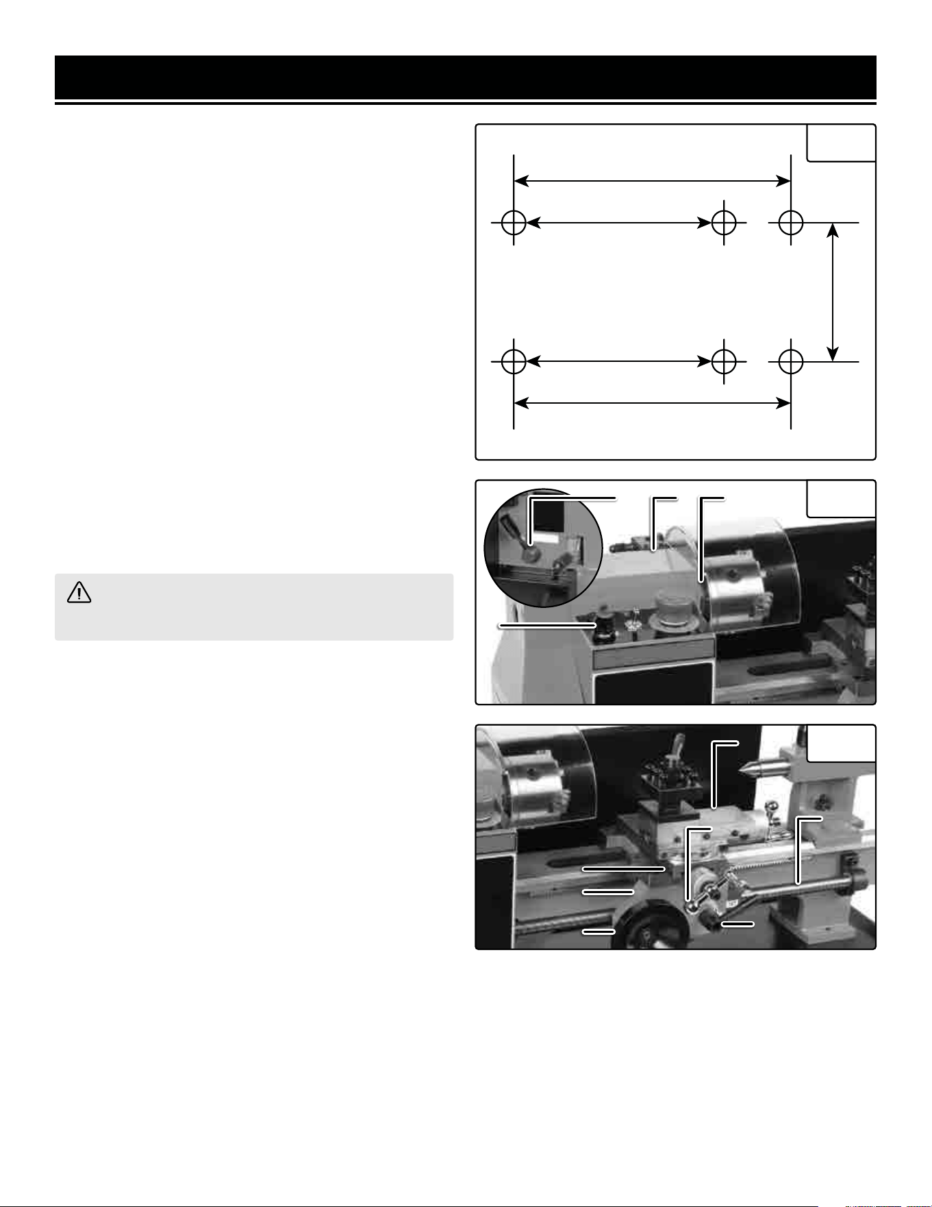
MOUNTING THE LATHE (FIG. 1)
The lathe should be mounted on a strong, heavy work-
bench. Take the necessary precautions when moving
the lathe. Assistance may be required. Bolt the machine
firmly to the workbench using the tapped holes. To do
this remove the 6mm screws securing the rubber feet
in place. Drill four 6mm (0.25-inch) clearance holes in
the worktop and find washers and 6mm screws long
enough to securely hold the unit in place.
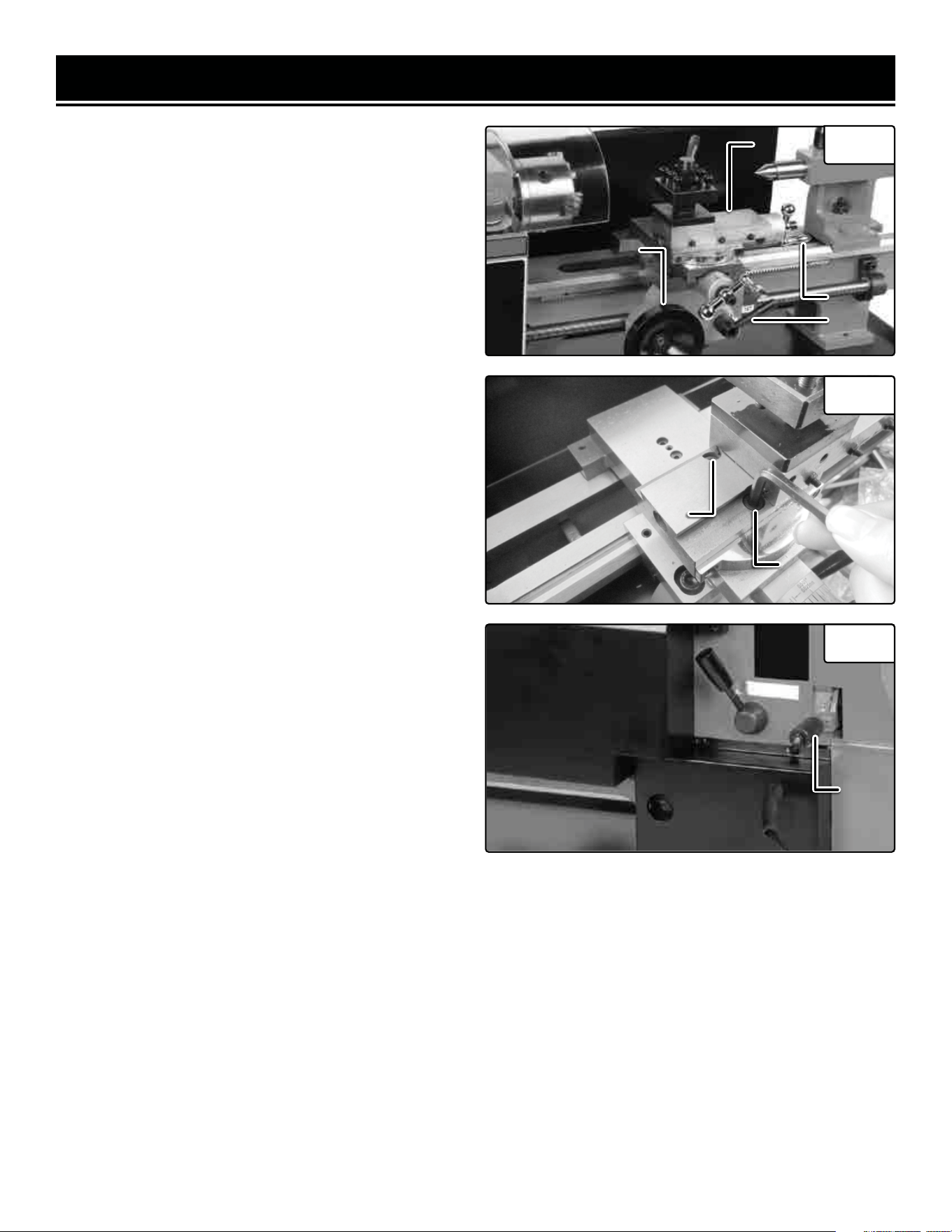
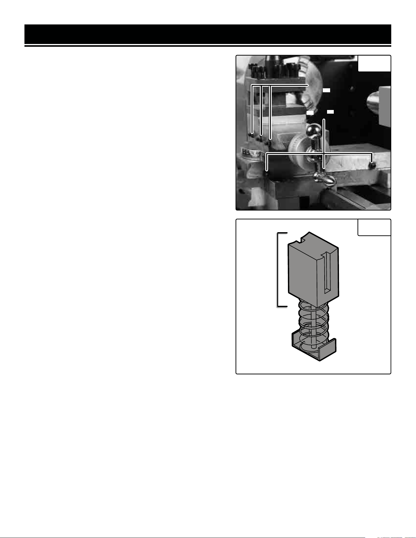
HEADSTOCK
The headstock (Fig. 2 - 1) contains the motor, pulleys
and the drive belt that turn the spindle used to create
your workpiece. The spindle (Fig. 2 - 2) has a MT3 taper
for use in conjunction with a face plate or chuck. The
spindle has a flange attached with 6 holes arranged to
mount different fixtures, such as chuck jaws and face
plates. The speed of the spindle is adjusted using the
speed control knob (Fig. 2 - 3) on the control panel. The
speed ranges can be swapped between two ranges with
the lever (Fig. 2 - 4) on the back of the headstock.
Fig. 1
Fig. 2
Fig. 3
WARNING! Do not change the speed range dur-
ing operation.
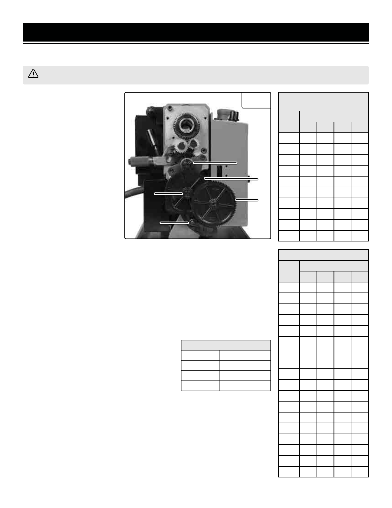
CARRIAGE
The carriage (Fig. 3 - 1) is the portion of the lathe that
moves the cross slide (Fig. 3 - 2) and compound slide
(Fig. 3 - 3) across the bed. It can be manually fed with
the handwheel (Fig. 3 - 5), or driven with the lead screw
(Fig. 3 - 4) by engaging the half nuts with the automatic
feed lever (Fig. 3 - 6).
CROSS SLIDE
The cross slide (Fig. 3 - 2) is used to move the tool
post and cutting tool across the bed, perpendicular to
the lead screw (Fig. 3 - 4) and the center axis of the
spindle. The cross slide is adjusted via a handle (Fig.
3 - 7) with precision tick marks, each indicating 0.001”.
This scale will rotate with the handle when it is turned
to feed the cross slide back and forth. Before beginning
turning, perform the following steps to adjust and zero
your cross slide:
1. Turn the handle counterclockwise to back the cross
slide about 0.015” away from your starting point, then
slowly turn the handle clockwise until the cross slide
returns to the starting position. This removes any play in
the slide and helps make the scale more accurate.
2. Hold the handle steady. With your other hand, rotate
the scale so the “0” lines up with the “0.000” mark on
the cross slide. From this point, the slide will remain ac-
curate as long as you only move it forward (toward the
splash guard on the back of the lathe).
3. Any time you back the slide away from your work-
piece, you will have to repeat steps 1 and 2 before mov-
ing the cross slide forward again for the next cut.
4
1
2
3
111
222
333
444
555
22.6 in. (575mm)
Model ML716
Model ML712
18.7 in. (475mm)
2.8 in.
(72mm)
666
11
777
OPERATION
COMPOUND SLIDE
The compound slide (Fig. 4 - 1) works similarly to the
cross slide, with a small handle (Fig. 4 - 2) and a scale
with tick marks every 0.001”. The compound slide can be
fed back and forth with this handle, similar to the cross
slide. It can also be rotated to an angle of your choice
and fed back and forth along this angle.
ADJUSTING THE COMPOUND SLIDE
1. Rotate the handle to move the compound slide back
and expose the two screws (Fig. 5 - 1). Loosen these two
screws with one of the included hex wrenches.
2. Rotate the compound slide to the desired angle and
retighten the bolts to lock it in place.
3. Turn the handle until your slide is at its starting point.
Then back the slide 0.015” from the starting point.
4. Slowly turn the handle to feed the slide forward until it
returns to the starting point.
5. Hold the handle in place and rotate the scale so the “0”
and “0.000” lines match and the scale is properly zeroed.
6. Repeat steps 3-5 for each cut and each time you adjust
the slide in order to get the most accurate cuts.
CARRIAGE FEED
The feed of the carriage along the axis of the spindle can
be done manually, or automatically by the lead screw and
gear train.
TO MANUALLY FEED THE CARRIAGE
Disengage the half nuts from the lead screw by pulling
UP on the feed lever (Fig. 4 - 3). Use the handlewheel on
the carriage (Fig. 4 - 4) to move it along the bed. Turning
it clockwise will move it away from the spindle and turn-
ing it counter-clockwise will move it towards the spindle.
Fig. 4 111
222
Fig. 5
111
111
333
444
Fig. 6
111
TO AUTOMATICALLY FEED THE CARRIAGE
1. Set the carriage to your starting point.
2. While the unit is still turned off, set the lead screw direction lever (Fig. 6 - 1) to either left feed or right feed, using
the label next to the lever. Choose your preferred direction based on the sticker next to the Lever.
3. Turn the lathe on and set it to the necessary RPM using the speed control knob.
4. Push the feed lever down to engage the lead screw and the automatic feed function.
5. Once the tool’s pass is finished, pull up on the lever to disengage the lead screw and the automatic feed. Move
the carriage back to the desired starting point, then push the feed lever down again and repeat.
NOTE: Increasing the spindle speed using the speed control knob will also increase the lead screw feed rate pro-
portionally.
12

OPERATION
TAILSTOCK
The tailstock (Fig. 7) is located on the bed opposite of the
headstock. It can be moved along the bed by loosening
the 17mm nut (Fig. 7 - 4) and pushing the tailstock to the
desired position. When it is in the desired spot, tighten
the 17mm nut to lock it in place. The tailstock is equipped
with an MT2 taper to use with appropriate tools, like the
included dead center, or an MT2 drill chuck. The tailstock
arrives properly aligned to the headstock from the fac-
tory. This allows the use of dead or live centers for turn-
ing between centers, as well as on-center drilling if using
a drill chuck. The tailstock quill is self-ejecting.
TAILSTOCK COMPONENTS
1. Tailstock Handwheel: Feeds the quill in and out of the
tailstock into the workpiece. Use to push a center into the
workpiece to hold it level horizontally, or to feed a drill
into the workpiece to create a hole.
Fig. 7
555
444
111
22
66
2
3
666
2. Offset Set Screw: Locks the tailstock position to allow for offset alignment (see next page).
3. Offset Cap Screw: Allows tailstock alignment to be adjusted to right or left of center (underside of tailstock).
4. Tailstock Lock Nut: Secures the tailstock in place on the bed.
5. Quill: Holds MT2 tapered tools in the tailstock.
6. Quill Lock: Secures the quill in place.
USING A CENTER WITH THE TAILSTOCK
If you are turning a workpiece with stock that hangs more than 2.5 times its diameter beyond the chuck jaws, it is
necessary to support the other end with a center and the tailstock. For projects that allow low RPM turning, a dead
center is okay. If higher RPMs are necessary, we recommend investing in a live center, which is equipped with a
bearing. To install:
1. Check the center and tailstock quill for any dirt, dust, debris or oil. Wipe both down, as excessive oil or dirt will
not allow the tapers to interlock.
2. Turn the tailstock handwheel until the quill protrudes approximately 1/2” inch from the tailstock.
3. Slide the center into the quill until it is snug; the tapers will keep the center in place. Keep the quill extended be-
tween 0 and 1.5 on the quill scale to keep it secure.
4. To remove the center, use the tailstock handle to retract the quill into the tailstock completely. This forces the
center out of the quill. Hold the head of the center with your hand to catch it as the center becomes loose.
13

OPERATION
OFFSETTING YOUR TAILSTOCK
WARNING! The tailstock comes from the factory properly aligned with the headstock.
The tailstock can also be used in an offset position to help turn tapers on a work piece. Adjusting the tailstock into
an offset position requires removing the tailstock from the bed and adjusting the offset screw on the bottom of the
tailstock. To properly offset the tailstock follow these steps (Fig. 8):
1. Use a 17mm wrench or socket to loosen the lock nut that holds the tailstock in place. Remove the stop screw on
the rear of the end of the bed (p. 8, item 18) using a 4mm hex wrench. Then slide the tailstock off the bed.
2. Loosen the offset set screw (Fig. 7 - 2) on the back of the tailstock, below the handle.
3. Loosen the offset cap screw (Fig. 7 - 3) on the bottom of the tailstock. Only loosen it enough so the tailstock can
slide.
4. Slide the tailstock back onto the bed and adjust it to the desired offset.
5. Tighten the offset setscrew to hold the tailstock at the proper offset position.
6. Slowly and carefully slide the tailstock off the bed and tighten the offset cap screw on the bottom.
7. Slide the tailstock back onto the bed, lock it in to the desired position and check your tolerances to makes sure it
is in the desired offset.
8. Repeat the previous steps in order to adjust the offset to the exact position necessary for your workpiece. Rein-
stall the stop screw on the end of the bed when finished.
TOOL POST
The tool post is used to hold your cutting tools and run the cutting edge along the workpiece you are turning. The
tool post can hold four tools at a time and has 4 preset stops at 90 degree intervals. It can also be set at any angle
in between these four presets. To install a cutting tool into the tool post follow these steps:
1. Determine which cutting tool will create the desired cut profile.
2. Loosen the screws in the top of the tool post on the edge you will place the cutting tool. Make sure the tool will
be secured by a minimum of two of these screws.
3. Place the tool under the screws and loosely tighten them, making sure it is perpendicular (or at the proper angle)
to the axis of the workpiece.
4. Align the tip of the tool with the centerline of the workpiece. If the workpiece centerline is higher, place shims
under the tool to raise its height. This machine uses 5/16” (8mm) tools. To determine if the tool tip is even with the
centerline, check the tool tip against the tip of the center in the tailstock. If the two tips are even or the tool tip is
below the center tip, the tool is the proper height. If the two tips are even or the tool tip is below the center team, the
tool is the proper size for the lathe. If the tool tip is below the center tip, it will need to be shimmed up to the height
of the center tip, otherwise you will see a small “button” on the workpiece when parting off. If the tool tip is higher
than the center tip, the tool is the wrong size for this lathe.
NOTE: You may also install an aftermarket quick-change tool post, size 0XA, if desired. The mounting bolt size is
M10x65mm.
14
OPERATION
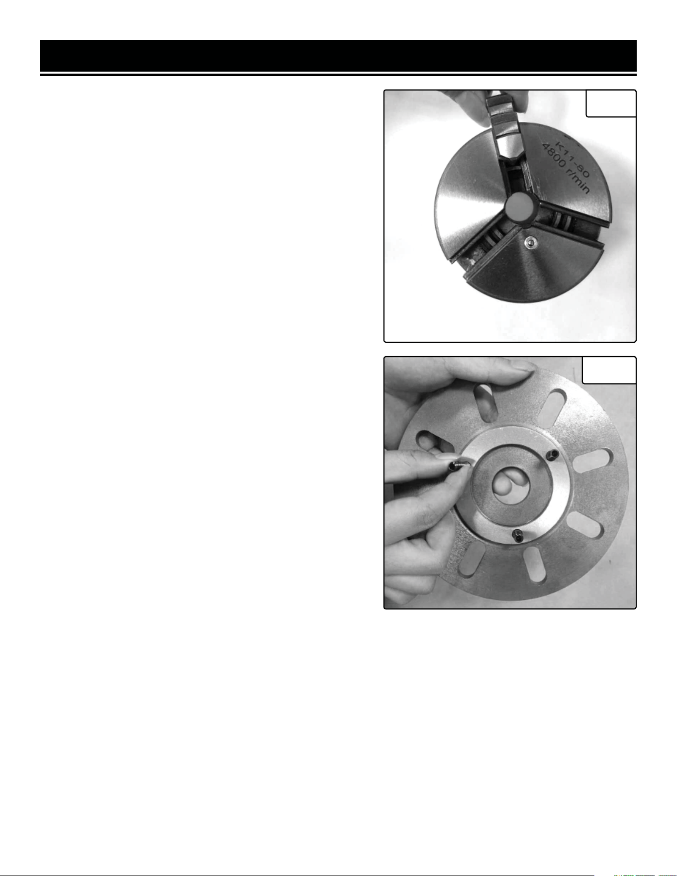
GEAR TRAIN
WARNING! Before making any of these adjustments, turn off and unplug the lathe from its power source.
NOTE: This lathe is designed
for use with plastic gears. This
is intentional, so that if you
make a mistake and a gear or
the lead screw binds up, a gear
will break, rather than the mo-
tor. The gears are much easier
and less expensive to replace.
The gear train is located on the
headstock opposite the spin-
dle. The drive gears are located
under a cover secured by two
socket head cap screws. The
gear train is used to drive the
lead screw’s speed, allowing
the auto-feed function to oper-
ate. As the gear train turns, it
Fig. 8
AAA
BBB
DDD
CCC
AdjusterAdjusterAdjuster
METRIC THREAD PITCH
CHART
Pitch
Gear Size (mm)
A B C D
0.4 20 50 40 60
0.5 20 50 / 60
0.6 40 50 30 60
0.7 40 50 35 60
0.8 40 50 40 60
1.0 20 60 / 30
1.25 50 40 / 60
1.5 40 60 / 40
1.75 35 60 / 30
2.0 40 60 / 30
THREADS PER INCH (TPI)
TPI
Gear Size (mm)
A B C D
12 40 65 / 30
13 40 65 60 30
14 40 65 / 35
16 40 65 / 40
18 40 65 / 45
19 40 50 60 57
20 40 65 / 50
22 40 65 / 55
24 40 65 / 60
26 40 60 / 65
28 20 65 / 35
32 20 65 / 40
36 20 65 / 45
38 20 50 60 57
40 20 65 / 50
44 20 65 / 55
48 20 65 / 60
52 20 60 / 65
turns the lead screw which moves the carriage across the bed of the lathe. The
direction is set using the lead screw direction lever. Adjusting it to forward will send
the carriage towards the headstock. Reverse sends it away, and neutral disengages
the lead screw so the carriage can be manually fed.
The feed rate of the lead screw can be set by changing the gears in the gear train
(Fig. 8). Switching the diameter of the gears and the order of the gears will change
the lead screw’s speed, allowing for different threads to be turned with the lathe.
The Threading Chart to the right shows the gear arrangements to use to achieve
different threads per inch (TPI) or metric pitches when using the lead screw.
FACTORY SETTINGS
A 20
B 80
C 20
D 80
To change the gears:
1. Using the 4mm hex wrench, remove the 2
mounting screws on the gear cover. Then remove
the gear cover.
2. Loosen the adjustment nut at the bottom of the
gear train to disengage the gears from one anoth-
er. Loosen the socket head cap screws that hold
each gear (or gear pair) on its shaft. Remove the necessary gears and replace them
with the appropriate gears. That is, the gears that have the proper number of teeth
in the positions called for (30, 40, 60, and 65 teeth). Note that some configurations
do not require gears in every position, and some require you to move the bushings
from one shaft to another for gears to properly fit in place.
3. Position the gears so their teeth will mesh together properly once the adjuster
is tightened.
15

OPERATION
NORMAL OPERATION
Before starting a turning, always plan your work ahead of time. Create a drawing or plan with all of the dimensions
you desire for the workpiece. Make sure to have all the measuring tools you will need to double and triple check
your cuts. Ensure that the feed rate, depth of cut (DOC), and spindle speed (RPM; depends on material, cutting tool
material and profile, DOC, desired surface finish, workpiece geometry, etc.) are all proper for your operation. To
avoid stalling the motor, we recommend that the DOC never exceed 0.5mm (0.0196 in), and should be kept below
0.25mm (about 0.01 in) whenever possible. Reduce spindle speed when taking a deeper cut.
Place the work into the chuck or attach to the faceplate. If necessary, use the tailstock center to support the opposite
end. If the tailstock is not needed, it can be removed completely by removing the stop screw and sliding the tailstock
off the bed.
After you have the work planned out, select the necessary cutting tools for the feature you wish to create and mount
them to the tool post. Make sure the tool tips are aligned with the center line of the workpiece, or slightly below
them.
Mark the end point for the cut on the work piece using a scriber. Line up the cutting tool with the end point and feed
in the cross slide until it just touches the surface of the workpiece. Then turn the spindle by hand to make sure there
is no interference between the carriage, cross slide, tool post, cutting tool, or chuck. It may be necessary to adjust
the compound slide or the workpiece in the chuck to get the proper amount of clearance.
When you have assured there is adequate clearance, back the cross slide away from the work piece and move the
carriage away from the head stock. Next zero out the cross-slide:
1. Feed the cross slide and the cutting tool to the starting position of the cut.
2. Back the cross slide 0.015” away from the work piece.
3. Slowly feed the cross slide back to the starting point.
4. Hold the handle to move the cross slide in place with one hand, and turn the dial of the gauge to make the 0 and
the 0.000 marks line up. The cross slide and cutting tool are now zeroed out.
5. If you have to back feed the cross slide at all, repeat steps 1 through 4.
NOTE: Before each pass of the cutting tool, it is recommended to add cutting oil to the work piece to reduce heat
and friction. Make sure to periodically add oil to the work piece as needed while turning.
MANUAL FEED
Double check the following before you begin turning:
1. The auto-feed lever is in the UP position, so the carriage half nuts are disengaged from the lead screw.
2. The Auto Feed Direction Lever is in NEUTRAL.
3. You are in the appropriate speed selection of HIGH/LOW for the material you are turning.
To know the proper RPM will take some experience. Harder metals should use a slower RPM while softer can use
a little faster RPM. If you are unsure, it is better to go slower than risk damage to the work, the cutting tool or the
lathe by using too high of an RPM. Feed rate and DOC are also very important. A deeper DOC needs a slower feed
rate and slower RPM, and vice versa.
Once you are ready to begin, switch the machine ON and set the RPM to your desired level. Slowly feed the cutting
tool into the work piece using the carriage handle. Slowly feed the cutting tool across the work piece until you reach
the marked end point. Retract the cross slide and cutting tool at this point one or two full revolutions. Return the
carriage to the starting point, and then feed the tool back in the same number of revolutions plus a small additional
feed rate in. Repeat this process until you have the desired amount of material cut away.
16

OPERATION
AUTOMATIC FEED
Once you have the cross slide set in position double check the following:
1. The auto feed direction lever is set to FORWARD.
2. The auto feed lever is disengaged from the lead screw.
3. You are in the appropriate speed selection range of HIGH/LOW.
4. The gear train is in the proper configuration, as this determines the feed rate of the lead screw. The factory setting
is okay for normal turning, but if you have been cutting screw threads you will need to reset the gear train to the
proper configuration.
CUTTING WITH THE AUTOMATIC FEED
NOTE: Ensure the DOC is appropriate for the cutting tool material, workpiece material, etc.
1. Position the cutting tool past the end of the workpiece, away from the tailstock. Make sure the tool is set to the
proper cutting depth. Always do shallow cuts, as cutting too deep too fast will damage the work piece, your cutting
tool, and your lathe. It is recommended to keep the cuts to 0.010” (0.25mm) or less at a time.
2. Double check that all the feed levers are set properly.
3. Turn the unit ON and set the spindle speed to the desired rate. Push the autofeed lever down to engage the half
nut with the lead screw.
4. Watch your cutting tool. When it reaches the end, quickly press UP on the auto feed lever and make sure it stays
disengaged from the lead screw.
5. Retract the cutting tool one or two turns using the cross slide handle. Feed the carriage back to the starting point,
and feed the tool back in one or two turns plus the additional cutting depth.
6. When ready for the next pass, engage the auto feed lever and repeat the previous steps until you have removed
the desired amount of material.
17

OPERATION
BEVEL CUTTING
In order to perform a bevel cut, it is necessary to use the compound slide as well as the cross slide. To align the
compound slide for a bevel cut, align it to the proper angle following the procedure in the “Compound Slide” section
on page 12.
Once the compound slide is aligned to the proper angle, follow these steps to create the bevel:
1. Mark your end point of the bevel if necessary, using the methods for a normal turning.
2. Set and zero out the cross slide to the proper starting point.
3. Turn the lathe on and set the spindle to the appropriate RPM.
4. Use the handle on the compound slide to feed the cutting tool along the end of the workpiece. This will create the
bevel cut at the angle you set it to.
5. Back off the cutting tool 2 turns and reset the compound slide to the starting point. Feed the cutting tool back in
to the cutting depth.
6. Repeat until your bevel is the desired length and position.
TO CUT THREADS
1. Adjust the compound slide so the tool is at the appropriate angle for the desired
thread.
2. Place the tool tip so that it is vertically centered and perpendicular to the work-
piece.
3. Engage the thread dial with the lead screw. The thread dial is located next to
the auto-feed lever on the carriage. There is a socket-head cap screw on the side;
loosen the screw using one of the included hex wrenches and adjust the body of the
thread dial so that its gear meshes with the threads on the lead screw. Tighten the
socket head cap screw, ensuring that the gear stays engaged with the lead screw
threads.
4. Use the gear ratio charts to determine the proper gear ratio and install the proper
gears (See “Gear Train” on page 15).
5. Turn the lathe on and set the RPM using the speed control knob. Make sure the
lead screw is feeding in the proper direction by engaging the feed lever. When you
are sure it is going in the right direction disengage the feed lever and turn off the
lathe. Ensure that the carriage is beyond the end of the workpiece.
6. Read the settings off the thread dial chart (left) to get the proper setting for the
thread dial. Make sure the thread dial always engages the half nut on the same mark
for every pass of the cutting tool. If you don’t do this, you may cut off threads cre-
ated in your previous cut. That is, the lever needs to be pushed down at the same
point in order to cut threads correctly. If you engage the lever when the dial is not
pointing to an indicator mark, you may stall the lead screw, which will cause it to
drop into Neutral and stop.
THREAD DIAL
TPI
SCALE
12 1, 3, 5, 7
13 1
14 1 or 5
16 1 - 8
18 1 or 5
19 1
20 1, 3, 5, 7
22 1 or 5
24 1 - 8
26 1 or 5
28 1, 3, 5, 7
32 1 - 8
36 1, 3, 5, 7
38 1 or 5
40 1 - 8
44 1, 3, 5, 7
48 1 - 8
52 1, 3, 5, 7
18
OPERATION
CHANGING THE JAWS IN YOUR CHUCK (FIG. 9)
1. Make sure your lathe is turned off and unplugged.
2. Insert the chuck key into the square hole of the chuck. Turn
the chuck key counterclockwise until all of the jaws come out
of the chuck.
3. Clean out each slot in the chuck making sure all dirt and
debris are removed.
4. Each jaw has a number or letter (1, 2, 3 or A, B, C) that cor-
responds to a number in the slot.
5. Take Jaw #1 and insert the chuck key into the chuck. Turn
the key clockwise while looking directly at the chuck so you can
see inside the slot. You will see the beginning of a lead thread
on the scroll of the chuck pass the opening, heading counter-
clockwise.
6. Insert Jaw #1 into this slot and turn the chuck key until the
thread engages the jaw.
7. Repeat these steps for jaws 2 and 3. Make sure to always
insert the jaws in order.
REMOVING A CHUCK OR FACEPLATE (FIG. 10)
1. Turn off and unplug your lathe! It is recommended to place a
piece of plywood over the bed underneath the spindle in order
to protect the bed if you drop the chuck/faceplate.
2. Hold the chuck or faceplate with your hand while using a
10mm wrench with your other hand to loosen and remove the
three hex nuts on the back of the spindle plate.
3. Pull the chuck/faceplate slowly off the spindle. It may be
necessary to tap the back surface of the faceplate/chuck with a
rubber mallet to get it off the spindle.
4. Make sure to keep track of the studs used for positioning the
chuck/faceplate, and set the piece aside.
INSTALLING THE CHUCK OR FACEPLATE
1. Insert the guide studs into the chuck/faceplate you wish to
install. To do this, make sure the studs extend at least ½” from
the surface of the chuck/faceplate.
2. Align the studs with the holes on the spindle and secure the
chuck/faceplate in place with the nuts using a 10mm wrench.
Fig. 9
Fig. 10
19
OPERATION
ADJUSTING THE GIBS
Although the factory setting should be fine, if you are having
trouble feeding the compound or cross slide, you may want to
adjust the gib screws. To adjust the gib you will need a 2mm
hex wrench and a 7mm combination wrench. Follow these
steps to adjust the gibs:
1. Turn off and unplug the lathe.
2. Loosen the three locknuts.
3. Test the sliding movement. Tighten and loosen the set screws
as necessary. The slides should move smoothly without play.
Readjust the set screws as needed.
4. Tighten the locknuts to keep the gibs set
CHECKING AND REPLACING MOTOR BRUSHES
The wear on the carbon brushes depends on how frequently
and how heavily the tool is used. To maintain maximum motor
efficiency, we recommend inspecting the two carbon brushes
every 50 hours of operation.
NOTE: Replacement carbon brushes (part no. 3455-137.1)
can be ordered at wenproducts.com. Only genuine WEN re-
placement brushes designed specifically for your tool should
be used. Carbon brushes are not covered under the two-year
warranty.
To replace the brushes for the lathe’s motor:
1. Turn off and unplug the lathe.
2. Use a flat-head screwdriver to remove the front and rear
brush caps from the motor. One can be accessed through the
hole in the front of the bed. The other can be accessed from the
back of the headstock, where the motor is exposed.
3. Remove the motor brushes and measure them. If they are
worn down to 3/16” or less, replace them with new ones. If not,
reinstall them in the motor.
4. Insert the new motor brushes. Ensure there is good contact
between the new brushes and the motor commutator.
5. Reattach the brush caps.
NOTE: Both brushes should be replaced simultaneously.
Fig. 11
CompoundCompound
SlideSlide
Compound
Slide
Cross SlideCross SlideCross Slide
Fig. 12
Carbon
Brush
Length
20

MAINTENANCE
Before each use make sure to check all of the parts of the lathe for any loose bolts or connections. Leave the gear
cover on to prevent chips from interfering with the geartrain. Make any adjustments to connections as necessary to
ensure all the parts are connected and will stay together during operation. Check all of the cutting tools to make sure
they are sharp. If the edge is dull, or has any nicks or cuts, either sharpen it or replace it. Dull or damaged cutting
tools are a hazard and should never be used.
Every time you use your lathe, make sure to check that all work surfaces are clean and undamaged. If there are any
chips or dents in the surface, work them out with an oil stone. Check that all of the moving parts pass over each
smoothly and can be moved without any interference.
Use your oil can to squirt a few drops of oil into the oilways of both bearings on the ends of the leadscrew. Do the
same for the oil way on the compound slide. The opening for this oilway is located between the two hex screws to
adjust the slide.
After use, make sure to clean away all metal shavings. Use a rag or brush to wipe away. It is recommended to wear
gloves while doing this to prevent getting any small metal shavings stuck in your hand. Make sure to wipe all of the
debris and dirt off the machine. Do not use an air compressor, as this can force shavings into the moving parts of
the lathe and cause damage. Make sure to remove all cutting tools and store in a safe place. Once the lathe is clean
it is recommended to lightly oil all of the surfaces to prevent any corrosion and keep the parts moving smoothly.
AFTER EACH USE
1. Clean all machine surfaces, including the chuck, and apply a thin layer of oil.
2. Put oil in each bearing on the lead screw.
3. Clean and oil the sliding surfaces of the bed, cross slide and compound slide.
EVERY 4 TO 6 MONTHS
1. Apply white lithium grease to the cross slide and compound slide lead screws.
2. Apply white lithium grease to all the drive gears.
3. Apply white lithium grease to the tailstock quill and screw.
4. Grease all of the transmission gears with a spray on grease.
21

PROBLEM CAUSE SOLUTION
Machine won’t
start
1. Emergency button is stuck down. 1. Try and release the button or replace it.
2. Fuse blown. 2. Replace fuse.
3. Damaged wiring.
3. Check for any visible damage, and check with a
multimeter for correct wiring.
4. PCB board damaged.
4. Check PCB board for damage, replace if neces-
sary.
5. Motor ON/OFF switch faulty. 5. Replace switch.
6. Spindle directional switch is bad. 6. Replace switch.
7. Motor is bad. 7. Test motor, repair or replace as needed.
8. Brushes are bad. 8. Replace the brushes.
Machine stalls
out during use
1. Material of workpiece is too hard. 1. Make sure the metal isn’t too hard for the unit.
2. PCB board is faulty. 2. Inspect and replace if necessary.
3. Variable speed knob is bad. 3. Test and replace.
4. Motor brushes are bad. 4. Replace brushes.
5. Belt slipping on the pulley. 5. Tighten pulleys, replace if needed.
6. Motor bearings went bad.
6. Test by rotating the shaft manually, grinding
noise or loose shaft indicates need to replace.
7. Machine is too small for the job.
7. Make sure cutting tools are sharp, use lower feed
rate and lubricant. Decrease the spindle speed and
DOC. If problem persists the tool may be too small.
8. Spindle rotation switch is bad. 8. Test switch, replace if needed.
Grinding or
clicking noise
from headstock
1. Set screws in the pulley aren’t tight. 1. Tighten set screws.
2. Motor fan contacting cover.
2. Check fan connection, tighten if necessary, or
replace fan/cover.
Motor
overheats
1. Motor is overloaded by work being
done.
1. Reduce load on the motor, lower the RPM, cut-
ting depth and feed rates.
2.Air circulation through motor is cut
off.
2. Clean all motor vents.
Motor bogs
down during
turning
operation
1. Cut or feed rate too high. 1. Reduce cut and feed rate.
2. RPM too high for the turning being
done.
2. Reduce RPM.
3. Cutting tool is dull or damaged. 3. Sharpen or replace.
4. Gears in the gear train are too tight.
4. Adjust the gears to have a very small amount of
play. Test the chuck’s rotation by hand.
TROUBLESHOOTING GUIDDE
22

PROBLEM CAUSE SOLUTION
Machine
vibrates when
started and
when allowed
to run
1. Workpiece unbalanced. 1. Center the workpiece and reinstall
2. Loose or broken belts. 2. Tighten or replace.
3. Pulleys misaligned. 3. Align pulleys.
4. Broken gear. 4. Inspect the gears and replace if needed.
5. Chuck or faceplate unbalanced. 5. Rebalance or replace if needed.
6. Spindle bearings worn out. 6. Replace bearings.
Poor surface
finish
1. Feed rate or RPM wrong. 1. Set the proper feed rate and RPM.
2. Dull cutting tool. 2. Sharpen cutting tool.
3. Too much play in gibs. 3. Tighten gibs (page 20).
4. Cutting tool set too high. 4. Remove tool or use a smaller tool.
Can’t remove
center or chuck
from tailstock
1. Quill isn’t retracted completely into
tailstock.
1. Turn the quill handle until the tool is forced out.
2. Debris in the quill.
2. Always clean taper surfaces. Try and force out
with WD40 and handle.
Cross slide,
compound slide,
or carriage have
poor feed
1. Gibs are out of alignment. 1. Adjust gib screws (page 20).
2. Handles are loose. 2. Tighten handles.
3. Lead screw worn out or needs greas-
ing.
3. Tighten fasteners on lead screw.
4. Bedways are worn and need greas-
ing.
4. Grease bedways.
5. Dirt, shavings or grime in bedways. 5. Clean bedways.
Surface finish
uneven from
end to end
1. Headstock and tailstock are mis-
aligned.
1. Realign the tailstock and headstock.
Chuck jaws
getting stuck
and hard to
move
1. Debris in the chuck jaws.
1. Remove jaws and clean out the chuck threads,
lubricate.
Carriage difficult
to feed or won’t
move
1. Gibs are too tight. 1. Loosen gibs.
2. Chips or debris in the bedway. 2. Clean bedways.
3. Carriage lock tightened down. 3. Release carriage lock.
4. Bedways dry. 4. Lubricate bedway.
5. Half nuts not engaged with lead
screw.
5. Engage half nuts with lead screw.
6. Gears broken. 6. Replace broken gears.
7. Loose feed handles. 7. Tighten handle.
Gear change
lever won’t shift
1. Gears misaligned. 1. Rotate spindle until the gears rotate into place.
TROUBLESHOOTING GUIDDE
23
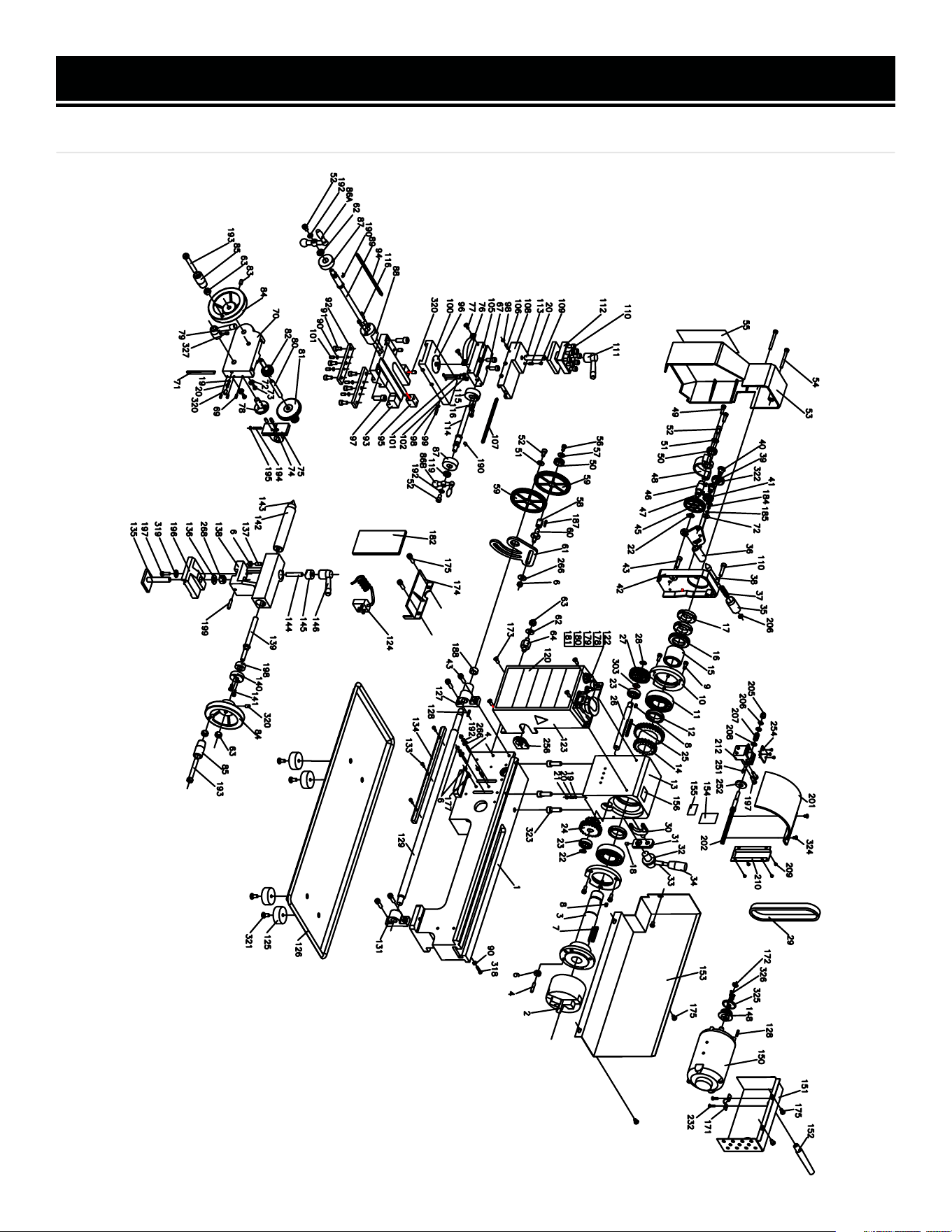
EXPLODED VIEW & PARTS LIST
MODEL ML712
24

EXPLODED VIEW & PARTS LIST
NO. PART NO. DESCRIPTION QTY.
1 3455-001 Bed Way 1
2 3455-002 3 Jaws Chuck 1
3 3455-003 Spindle 1
4 3455-004 Set Screw M6x25 5
6 3455-005 Nut M6 10
7 3455-006 Key M5x40 1
8 3455-007 Key M4x8 2
9 3455-008 Screw M5x12 6
10 3455-009 Spindle Bearing Cover 2
11 3455-010 Ball Bearing 6206ZZ 2
12 3455-011 Spacer 2
13 3455-012 Headstock Casting 1
14 3455-013
High/Low Transmission
Gear 21/29T
1
15 3455-014 Spacer 1
16 3455-015 Spur Gear 45T 1
17 3455-016 Nut M27-1.5 2
18 3455-017 Set Screw M5x8 1
19 3455-018 Steel Ball 2
20 3455-019 Compression Spring 3
21 3455-020 Set Screw M6x6 1
22 3455-021 Retaining Ring 12mm 2
23 3455-022 Ball Bearing 6001 2
24 3455-023 Transmission Gear 12T/20T 1
25 3455-024 Key M4x45 1
26 3455-025 H/L Gear Shaft 1
27 3455-026 Pulley 1
28 3455-027 Retaining Ring 10mm 1
29 3455-028 Timing Belt 136 (1.5x70) 1
30 3455-029 High/Low Shifting Fork 1
31 3455-030 High/Low Shifting Arm 1
32 3455-031 High/Low Shifting Knob 1
33 3455-032 High/Low Shifting Lever 1
34 3455-033 High/Low Shifting Grip 1
35 3455-034 Handle 1
36 3455-035 Handle Mount 1
37 3455-036 Compressive Spring 1
38 3455-037 Indicator 1
39 3455-038 Pinion 25T 1
40 3455-039 Support Screw 2
41 3455-040 Pinion 20T 1
NO. PART NO. DESCRIPTION QTY.
42 3455-041 Headstock Cover 1
43 3455-042 Screw M6x20 5
45 3455-043 Gear 45T 1
46 3455-044 Shaft 1
47 3455-045 Key 4x8 1
48 3455-046 Mount 1
49 3455-047 Screw M5x18 2
50 3455-048 Pinion 20T 2
51 3455-049 Washer 6mm 2
52 3455-050 Screw M6x8 4
53 3455-051 Transmission Cover 1
54 3455-052 Screw M5x45 2
55 3455-053 TPI Cutting Chart 1
56 3455-054 Screw M5x8 1
57 3455-055 Washer 5mm 1
58 3455-056 Bushing With Key 1
59 3455-057 Gear 80T 2
60 3455-058 Shaft 1
61 3455-059 Support Plate 1
62 3455-060 Washer 8mm 2
63 3455-061 Nut M8 4
64 3455-062 Shaft 1
67 3455-063 Screw M5x16 2
69 3455-064 Screw M4x10 3
70 3455-065 Apron 1
71 3455-066 Gib Strip 1
72 3455-067 Washer 5mm 3
73 3455-068 Screw M4x8 2
74 3455-069 Shaft 2
75 3455-070 Half Nut Base 2
76 3455-071 Angle Block 1
77 3455-072 Screw M4x10 2
78 3455-073 Groove Cam 1
79 3455-074 Handle 1
80 3455-075 Shaft 1
81 3455-076 Feeding Gear (A) 11T/54T 1
82 3455-077 Feeding Gear (B) 24T 1
83 3455-078 Screw M6x10 1
84 3455-079 Handwheel 2
85 3455-080
Knob & Screw, M8x55 +
Nut M8
2
MODEL ML712
25

EXPLODED VIEW & PARTS LIST
NO. PART NO. DESCRIPTION QTY.
86A 3455-081 Three-Ball Handle (Large) 1
86B 3455-082 Three-Ball Handle (Small) 1
87 ML712-087 Dial (Imperial) 2
88 ML712-088 Bracket (Imperial) 1
89 ML712-089 Feed Screw (Imperial) 1
90 3455-086 Nut M5 5
91 3455-087 Screw M6x12 6
92 3455-088 Slide Plate 2
93 3455-089 Saddle 1
94 3455-090 Gib Strip 1
95 ML712-095 Feed Nut (Imperial) 1
96 3455-092 Swivel Disk 1
97 3455-093 Screw M8x20 2
98 3455-094 Nut M4 8
99 3455-095 Screw M4x16 3
100 3455-096 Cross Slide 1
101 3455-097 Screw M5x10 5
102 3455-098 Screw M4x8 2
105 ML712-105 Compound Rest (Lower) 1
106 3455-100 Screw M4x14 3
107 3455-101 Gib Strip 1
108 3455-102 Compound Rest (Upper) 1
109 3455-103 Positioning Pin 1
110 3455-104 Screw M6x25 9
111 3455-105 Clamping Lever 1
112 3455-106 Tool Rest 1
113 3455-107 Stud M10x65 1
114 ML712-114 Cross Feed Screw (Imperial) 1
115 ML712-115 Bracket 1
116 3455-110 Screw M4x12 4
119 3455-111 Nut M18 1
120 3455-112 Main Label 1
122 3455-113 Information Label 1
123 3455-114 Electronics Cover 1
124 3455-115 Power Cord 1
125 3455-116 Rubber Foot 4
126 3455-117 Chip Tray 1
127 3455-118 Left Leadscrew Bracket 1
128 3455-119 Key 3x16 2
129 ML712-129 Leadscrew (Imperial) 1
131 3455-121 Right Leadscrew Bracket 1
133 3455-122 Screw M3x10 3
134 3455-123 Rack 1
NO. PART NO. DESCRIPTION QTY.
135 3455-124 Clamp Plate 1
136 3455-125 Washer M10 1
137 3455-126 Screw M6x14 1
138 3455-127 Tailstock Casting 1
139 3455-128 Tailstock Screw 1
140 ML712-140 Bracket 1
141 3455-130 Screw M4x10 4
142 3455-131 Tailstock Quill 1
143 3455-132 Center 1
144 3455-133 Stud M8x40 1
145 3455-134 Clamp 1
146 3455-135 Handle 1
148 3455-136 Pulley 1
150 3455-137 Motor 1
N.P. 3455-137.1 Carbon Brushes, Set of 2 1
151 3455-138 Motor Cover 1
152 3455-139 Power Cord Strain Relief 1
153 3455-140 Rear Chip Guard 1
154 ML712-154 Feed Direction Label 1
155 3455-141 H/L Label 1
156 3455-143 Warning Label 1
N.P. 3455-144 Gear 30T 1
N.P. 3455-145 Gear 35T 1
N.P. 3455-146 Gear 40T 2
N.P. 3455-147 Gear 45T 1
N.P. 3455-148 Gear 50T 1
N.P. 3455-149 Gear 55T 1
N.P. 3455-150 Gear 57T 1
N.P. 3455-151 Gear 60T 1
N.P. 3455-152 Gear 65T 1
N.P. 3455-153 External Jaw Set 1
N.P. ML712-119 Chuck Key 1
171 3455-155 Clamping Bracket 1
172 3455-156 Retaining Ring Ø8mm 1
173 3455-157 Screw M5x8 4
174 3455-158 Guard 1
175 3455-159 Screw M5x8 7
177 3455-160 Screw M6x20 2
178 ML712-178 Emergency Stop Switch 1
179 3455-162 Fuse Box 1
180 ML712-180 Variable Speed Control Knob 1
181 ML712-181 Toggle Switch 1
182 3455-165 PCB, 120V 1
26

EXPLODED VIEW & PARTS LIST
NO. PART NO. DESCRIPTION QTY.
184 3455-166 Screw M5x10 1
185 3455-167 Spring Washer, 5mm 1
187 3455-168 Key 3x16 1
188 3455-169 Small Spacer 1
190 3455-170 Spring 2
192 3455-171 Washer 6mm 4
193 3455-172 Screw M8x55 2
194 3455-173 Screw M4x38 1
195 3455-174 Nut M4 1
196 3455-175 Tailstock Base Plate 1
197 3455-176 Screw M5x16 3
198 3455-177 Sleeve 1
199 3455-178 Screw M5x25 1
201 3455-179 Chuck Guard 1
202 3455-180 Shaft 1
205 3455-181 Cap Nut M6 1
206 3455-182 Hex Nut M6 2
207 3455-183 Compression Spring 1
208 3455-184 Washer 6mm 2
209 3455-185 Screw M3x4 4
210 3455-186 Switch Cover 1
212 3455-187 Block 1
232 3455-188 Screw, M4x6 2
NO. PART NO. DESCRIPTION QTY.
251 3455-194 Cylinder Pin, 3x8mm 1
253 3455-195
Self-tapping Screw,
ST2.9x4.5
3
254 3455-196 Cover 1
256 3455-198 Dust Cover 1
257 3455-199 Lead Screw Cover 1
258 3455-200 Washer 4mm 3
266 3455-201 Washer 6mm 3
268 3455-202 Hex Nut M10 1
270 3455-203 Support Pin 1
272 3455-204 Protective Cover 1
303 3455-205 Washer 10mm 1
318 3455-206 Screw M5x20 1
319 3455-207 Washer 5mm 1
320 3455-208 Screw M6x10 4
321 3455-209 Screw M6x16 4
322 3455-210 Key, 3x6mm 1
323 3455-211 Screw M8x25 3
324 3455-212 Screw M4x8 2
325 3455-213 Flange 1
326 3455-214
Self-tapping Screw,
ST2.9x9.5
2
327 3455-215 Screw M6x8 1
NOTE: Parts that wear down over the course of normal use (like saw blades, carbon brushes, etc.)
are not covered by the two-year warranty.
NOTE: Not all parts may be available for purchase.
27
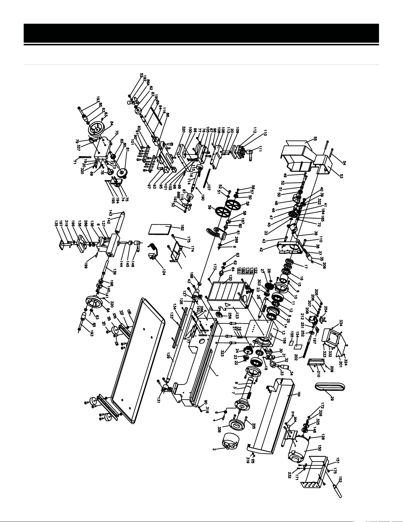
EXPLODED VIEW & PARTS LIST
MODEL ML716
28

EXPLODED VIEW & PARTS LIST
NO. PART NO. DESCRIPTION QTY.
1 ML716-001 Bed Way 1
2 ML716-002 3 Jaws Chuck 1
3 3455-003 Spindle 1
4 3455-004 Set Screw M6x25 5
6 3455-005 Nut M6 10
7 3455-006 Key M5x40 1
8 3455-007 Key M4x8 2
9 3455-008 Screw M5x12 6
10 3455-009 Spindle Bearing Cover 2
11 3455-010 Ball Bearing 6206ZZ 2
12 3455-011 Spacer 2
13 3455-012 Headstock Casting 1
14 3455-013
High/Low Transmission
Gear 21/29T
1
15 3455-014 Spacer 1
16 3455-015 Spur Gear 45T 1
17 3455-016 Nut M27-1.5 2
18 3455-017 Set Screw M5x8 1
19 3455-018 Steel Ball 2
20 3455-019 Compression Spring 3
21 3455-020 Set Screw M6x6 1
22 3455-021 Retaining Ring 12mm 2
23 3455-022 Ball Bearing 6001 2
24 3455-023 Transmission Gear 12T/20T 1
25 3455-024 Key M4x45 1
26 3455-025 H/L Gear Shaft 1
27 3455-026 Pulley 1
28 3455-027 Retaining Ring 10mm 1
29 3455-028 Timing Belt 136 (1.5x70) 1
30 3455-029 High/Low Shifting Fork 1
31 3455-030 High/Low Shifting Arm 1
32 3455-031 High/Low Shifting Knob 1
33 3455-032 High/Low Shifting Lever 1
34 3455-033 High/Low Shifting Grip 1
35 3455-034 Handle 1
36 3455-035 Handle Mount 1
37 3455-036 Compressive Spring 1
38 3455-037 Indicator 1
39 3455-038 Pinion 25T 1
40 3455-039 Support Screw 2
41 3455-040 Pinion 20T 1
NO. PART NO. DESCRIPTION QTY.
42 3455-041 Headstock Cover 1
43 3455-042 Screw M6x20 5
45 3455-043 Gear 45T 1
46 3455-044 Shaft 1
47 3455-045 Key 4x8 1
48 3455-046 Mount 1
49 3455-047 Screw M5x18 2
50 3455-048 Pinion 20T 2
51 3455-049 Washer 6mm 2
52 3455-050 Screw M6x8 4
53 3455-051 Transmission Cover 1
54 3455-052 Screw M5x45 2
55 3455-053 TPI Cutting Chart 1
56 3455-054 Screw M5x8 1
57 3455-055 Washer 5mm 1
58 3455-056 Bushing With Key 1
59 3455-057 Gear 80T 2
60 3455-058 Shaft 1
61 3455-059 Support Plate 1
62 3455-060 Washer 8mm 2
63 3455-061 Nut M8 4
64 3455-062 Shaft 1
67 3455-063 Screw M5x16 2
69 3455-064 Screw M4x10 3
70 3455-065 Apron 1
71 3455-066 Gib Strip 1
72 3455-067 Washer 5mm 3
73 3455-068 Screw M4x8 2
74 3455-069 Shaft 2
75 3455-070 Half Nut Base 2
76 3455-071 Angle Block 1
77 3455-072 Screw M4x10 2
78 3455-073 Groove Cam 1
79 3455-074 Handle 1
80 3455-075 Shaft 1
81 3455-076 Feeding Gear (A) 11T/54T 1
82 3455-077 Feeding Gear (B) 24T 1
83 3455-078 Screw M6x10 1
84 3455-079 Handwheel 2
85 3455-080
Knob & Screw, M8x55 +
Nut M8
2
MODEL ML716
29

EXPLODED VIEW & PARTS LIST
NO. PART NO. DESCRIPTION QTY.
86A 3455-081 Three-Ball Handle (Large) 1
86B 3455-082 Three-Ball Handle (Small) 1
87 ML712-087 Dial (Imperial) 2
88 ML712-088 Bracket (Imperial) 1
89 ML712-089 Feed Screw (Imperial) 1
90 3455-086 Nut M5 5
91 3455-087 Screw M6x12 6
92 3455-088 Slide Plate 2
93 3455-089 Saddle 1
94 3455-090 Gib Strip 1
95 ML712-095 Feed Nut (Imperial) 1
96 3455-092 Swivel Disk 1
97 3455-093 Screw M8x20 2
98 3455-094 Nut M4 8
99 3455-095 Screw M4x16 3
100 3455-096 Cross Slide 1
101 3455-097 Screw M5x10 5
102 3455-098 Screw M4x8 2
105 ML712-105 Compound Rest (Lower) 1
106 3455-100 Screw M4x14 3
107 3455-101 Gib Strip 1
108 3455-102 Compound Rest (Upper) 1
109 3455-103 Positioning Pin 1
110 3455-104 Screw M6x25 9
111 3455-105 Clamping Lever 1
112 3455-106 Tool Rest 1
113 3455-107 Stud M10x65 1
114 ML712-114 Cross Feed Screw (Imperial) 1
115 ML712-115 Bracket 1
116 3455-110 Screw M4x12 4
119 3455-111 Nut M18 1
120 3455-112 Main Label 1
122 ML716-122 Information Label 1
123 ML716-123 Electronics Cover 1
124 3455-115 Power Cord 1
125 ML716-125 Rubber Foot 4
126 ML716-126 Chip Tray 1
127 3455-118 Left Leadscrew Bracket 1
128 3455-119 Key 3x16 2
129 ML716-129 Leadscrew (Imperial) 1
131 3455-121 Right Leadscrew Bracket 1
133 3455-122 Screw M3x10 3
134 ML716-134 Rack 1
NO. PART NO. DESCRIPTION QTY.
135 3455-124 Clamp Plate 1
136 3455-125 Washer M10 1
137 3455-126 Screw M6x14 1
138 3455-127 Tailstock Casting 1
139 3455-128 Tailstock Screw 1
140 ML712-140 Bracket 1
141 3455-130 Screw M4x10 4
142 3455-131 Tailstock Quill 1
143 3455-132 Center 1
144 3455-133 Stud M8x40 1
145 3455-134 Clamp 1
146 3455-135 Handle 1
148 3455-136 Pulley 1
150 3455-137 Motor 1
N.P. 3455-137.1 Carbon Brushes, Set of 2 1
151 3455-138 Motor Cover 1
152 3455-139 Power Cord Strain Relief 1
153 ML716-153 Rear Chip Guard 1
154 ML712-154 Feed Direction Label 1
155 3455-141 H/L Label 1
156 3455-143 Warning Label 1
N.P. 3455-144 Gear 30T 1
N.P. 3455-145 Gear 35T 1
N.P. 3455-146 Gear 40T 2
N.P. 3455-043 Gear 45T 1
N.P. 3455-148 Gear 50T 1
N.P. 3455-149 Gear 55T 1
N.P. 3455-150 Gear 57T 1
N.P. 3455-151 Gear 60T 1
N.P. 3455-152 Gear 65T 1
N.P. 3455-153 External Jaw Set 1
N.P. ML712-119 Chuck Key 1
171 3455-155 Clamping Bracket 1
172 3455-156 Retaining Ring Ø8mm 1
173 3455-157 Screw M5x8 4
174 3455-158 Guard 1
175 3455-159 Screw M5x8 7
177 3455-160 Screw M6x20 2
178 ML712-178 Emergency Stop Switch 1
179 3455-162 Fuse Box 1
180 ML712-180 Variable Speed Control Knob 1
181 ML712-181 Toggle Switch 1
182 3455-165 PCB, 120V 1
30

EXPLODED VIEW & PARTS LIST
NOTE: Parts that wear down over the course of normal use (like saw blades, carbon brushes, etc.)
are not covered by the two-year warranty.
NOTE: Not all parts may be available for purchase.
NO. PART NO. DESCRIPTION QTY.
184 3455-166 Screw M5x10 1
185 3455-167 Spring Washer, 5mm 1
187 3455-168 Key 3x16 1
188 3455-169 Small Spacer 1
190 3455-170 Spring 2
192 3455-171 Washer 6mm 4
193 3455-172 Screw M8x55 2
194 3455-173 Screw M4x38 1
195 3455-174 Nut M4 1
196 3455-175 Tailstock Base Plate 1
197 3455-176 Screw M5x16 3
198 3455-177 Sleeve 1
199 3455-178 Screw M5x25 1
201 ML716-201 Chuck Guard 1
202 3455-180 Shaft 1
204 ML716-204 Motor Base 1
205 3455-181 Cap Nut M6 1
206 3455-182 Hex Nut M6 2
207 3455-183 Compression Spring 1
208 3455-184 Washer 6mm 2
209 3455-185 Screw M3x4 4
210 3455-186 Switch Cover 1
212 3455-187 Block 1
232 3455-188 Screw, M4x6 7
251 3455-194 Cylinder Pin, 3x8mm 1
253 3455-195
Self-tapping Screw,
ST2.9x4.5
3
254 3455-196 Cover 1
NO. PART NO. DESCRIPTION QTY.
256 3455-198 Dust Cover 1
257 3455-199 Lead Screw Cover 1
258 3455-200 Washer 4mm 3
266 3455-201 Washer 6mm 3
268 3455-202 Hex Nut M10 1
270 3455-203 Support Pin 1
272 3455-204 Protective Cover 1
303 3455-205 Washer 10mm 1
318 3455-206 Screw M5x20 1
319 3455-207 Washer 5mm 1
320 3455-208 Screw M6x10 4
321 3455-209 Screw M6x16 4
322 3455-210 Key, 3x6mm 1
323 3455-211 Screw M8x25 3
324 3455-212 Screw M4x8 2
325 3455-213 Flange 1
326 3455-214
Self-tapping Screw,
ST2.9x9.5
2
327 3455-215 Screw M6x8 1
331 ML716-331 Bolt, M8x30 3
332 ML716-332 Protective Plate 1
333 ML716-333 Nut, M3 4
334 ML716-334 Screw, M3x6 4
335 ML716-335 Bolt, M8x30 3
336 ML716-336 Chuck Plate 1
337 ML716-337 Hex Nut 4
338 ML716-338 Tray Bracket 2
339 ML716-339 Screw, M6x20 8
31

WARRANTY STATEMENT
WEN Products is committed to building tools that are dependable for years. Our warranties are consistent with this
commitment and our dedication to qualit
y.
LIMITED WARRANTY OF WEN PRODUCTS FOR HOME USE
GRE
AT LAKES TECHNOLOGIES, LLC (“Seller”) warrants to the original purchaser only, that all WEN
consumer
power tools will be free from defects in material or workmanship during personal use for a period of two (2) years
used
for professional or commercial use. Purchaser has 30 days from the date of purchase to report missing or
damaged parts.
SELLER’S
SOLE OBLIGATION AND YOUR EXCLUSIVE REMEDY under this Limited Warranty and, to the extent per-
mitted
by law, any warranty or condition implied by law, shall be the replacement of parts, without charge, which a
re
defective
in material or workmanship and which have not been subjected to misuse, alteration, careless handling,
misrepair
, abuse, neglect, normal wear and tear,
improper maintenance, or other conditions adversely affecting the
Product
or the component of the Product, whether by accident or intentionally, by persons other than Seller. To
make
a claim under this Limited Warranty, you must make sure to keep a copy of your proof of purchase that
clearly
-
dor
of Great Lakes Technologies, LLC. Purchasing through third party vendors, including but not limited to garage
sales,
pawn shops, resale shops, or any other secondhand merchant, voids the warranty included with this
product.
Contact [email protected] or 1-847-429-9263 with the following information to make arrangements:
your
shipping address, phone number, serial number, required part numbers, and proof of purchase. Damaged
or
defective parts and products may need to be sent to WEN before the replacements can be shipped out.
-
turning
a product for warranty service, the shipping charges must be prepaid by the purchaser. The product
must
be
shipped in its original container (or an equivalent), properly packed to withstand the hazards of shipment. The
product
must be fully insured with a copy of the proof of purchase enclosed. There must also be a description of
the
will be returned and shipped back to the pur
chaser at no charge for addresses within the contiguous United States.
THIS
LIMITED WARRANTY DOES NOT APPLY TO ITEMS THAT WEAR OUT FROM REGULAR USAGE OVER TIME,
INCLUDING
BELTS, BRUSHES, BLADES, BATTERIES, ETC. ANY IMPLIED WARRANTIES SHALL BE LIMITED IN
DUR
ATION TO TWO (2) YEARS FROM DATE OF PURCHASE. SOME STATES IN THE U.S. AND SOME CANADIAN
PROVINCES
DO NOT ALLOW LIMITATIONS ON HOW LONG AN IMPLIED WARRANTY LASTS, SO THE ABOVE LIMI-
TAT
ION MAY NOT APPLY TO YOU.
IN
NO EVENT SHALL SELLER BE LIABLE FOR ANY INCIDENTAL OR CONSEQUENTIAL DAMAGES (INCLUDING
BUT
NOT LIMITED TO LIABILITY FOR LOSS OF PROFITS) ARISING FROM THE SALE OR USE OF THIS PRODUCT.
SOME ST
ATES IN THE U.S. AND SOME CANADIAN PROVINCES DO NOT ALLOW THE EXCLUSION OR LIMITAT
ION
OF
INCIDENTAL OR CONSEQUENTIAL DAMAGES, SO THE ABOVE LIMITATION OR EXCLUSION MAY NOT APPLY
TO YOU.
THIS
LIMITED WARRANTY GIVES YOU SPECIFIC LEGAL RIGHTS, AND YOU MAY ALSO HAVE OTHER RIGHTS
WHICH
VARY FROM STATE TO STATE IN THE U.S., PROVINCE TO PROVINCE IN CANADA AND FROM COUNTRY
TO COUNT
RY.
THIS
LIMITED WARRANTY APPLIES ONLY TO ITEMS SOLD WITHIN THE UNITED STATES OF AMERICA, CANA-
DA
AND THE COMMONWEALTH OF PUERTO RICO. FOR WARRANTY COVERAGE WITHIN OTHER
COUNTRIES,
CONT
ACT THE WEN CUSTOMER SUPPORT LINE. FOR WARRANTY PARTS OR PRODUCTS REPAIRED UNDER
W
ARRANTY SHIPPING TO ADDRESSES OUTSIDE OF THE CONTIGUOUS UNITED STATES, ADDITIONAL
SHIPPING
CHARGES MAY APPLY.
32
V. 2024.03.25