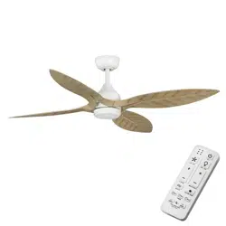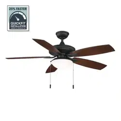
USE AND CARE GUIDE
42 IN. CEILING FAN
THD_RH5H1_UD42.eg 18年11月07日 下午15:20
An electronic copy of this user manual can also be obtained online at
homedepot.com
Model # RH5H1-ORB/RH5H1-BN
2
Table of Contents
Table of Contents ....................................2
Safety Information ...................................2
Warranty ..........................................3
Pre-Installation .....................................4
Operation .........................................10
Care and Cleaning ..................................11
Troubleshooting ....................................11
Safety Information
PLEASE READ AND SAVE THESE INSTRUCTIONS.
1. To reduce the risk of electric shock, ensure electricity has been
turned off at the circuit breaker or fuse box before beginning.
2. All wiring must be in accordance with the National Electrical
Code, ANSI/NFPA 70, and local electrical codes. Electrical
installation should be performed by a qualied licensed
electrician.
3. The outlet box and support structure must be securely mounted
and capable of reliably supporting a minimum of 35 pounds. Use
only UL Listed outlet boxes marked “FOR FAN SUPPORT.”
4. Do not operate the reversing switch while the fan blades are in
motion. The fan must be turned off and blades stopped before
reversing blade direction
5. Avoid placing objects in the path of the blades. To avoid personal
injury or damage to the fan and other items, be cautious when
working around or cleaning the fan
6. Do not use water or detergents when cleaning the fan or fan
blades. A dry dust cloth or lightly dampened cloth will be
suitable for most cleaning.
7. After making electrical connections, spliced conductors should
be turned upward and pushed carefully up into the outlet box.
The wire should be spread apart with the grounded conductor
and the equipment-grounding conductor on one side of the
outlet box. Splices after being made should be turned upward
and pushed carefully up into the outlet box.
8. Electrical diagrams are for reference only. Light kits that are not
packed with the fan must be UL Listed and marked suitable for
use with the model fan you are installing. Switches must be UL
General Use Switches. Refer to the instructions packaged with
the light kits and switches for proper assembly.
WARNING: Before servicing or cleaning unit, switch power
off at service panel, and lock service disconnecting means to
prevent power from being switched on accidentally. When the
service disconnecting means cannot be locked, securely fasten
a prominent warning.
WARNING: To reduce the risk of re, electric shock or
personal injury, mount to an outlet box acceptable for fan
support of 15.9 Kg (35 lbs) or less. Use mounting screws
provided with the outlet box. Most outlet boxes commonly
used for the support of lighting xtures are not acceptable for
fan support and may need to be replaced. Consult a qualied
electrician if in doubt.
WARNING: To reduce the risk of personal injury, do not bend
the blade brackets when installing the brackets, balancing the
blades, or cleaning the fan. Do not insert foreign objects in
between rotating fan blades.
WARNING: To reduce the risk of re or electric shock, do not
use this fan with any solid-state speed control device.
CAUTION: To reduce the risk of injury to person, the fan
must be mounted with a minimum of 7 feet clearance from the
trailing edge of the blades to the oor.
RH5H1
UD42
THD_RH5H1_UD42.eg 18年11月07日 下午15:20
3
Warranty
LIMITED WARRANTY
WHAT IS COVERED
The retailer warrants the fan motor to be free from defects in workmanship and material present at time of shipment from the
factory for a period of lifetime after the date of purchase by the original purchaser. The retailer also warrants that all other fan parts,
excluding any glass or acrylic blades, to be free from defects in workmanship and material at the time of shipment from the factory for a
period of one year after the date of purchase by the original purchaser. We agree to correct such defects without charge or at our option
replace with a comparable or superior model if the product is returned to the retailer. To obtain warranty service, you must present a
copy of the receipt as proof of purchase. All costs of removing and reinstalling the product are your responsibility. Damage to any part
normal and should not be considered a defect. Servicing performed by unauthorized persons shall render the warranty invalid. There is no
other express warranty. The retailer hereby disclaims any and all warranties, including but not limited to. Those of merchantability and
above limitation may not apply to you. The retailer shall not be liable for incidental, consequential, or special damages arising out of or
in connection with product use or performance except as may otherwise be accorded by law. Some states do not allow the exclusion of
and you may also have other rights which vary from state to state. This warranty supersedes all prior warranties. Shipping costs for any
return of product as part of a claim on the warranty must be paid by the customer.
Fan Size Speed Volts Amps Watts RPM CFM N.W. G.W. C.F.
42 in.
Low 120 1N/A
N/A
N/A
430
4.8 kgMed 120 28
45
140 2163
High 120 180 2737
Pre-Installation
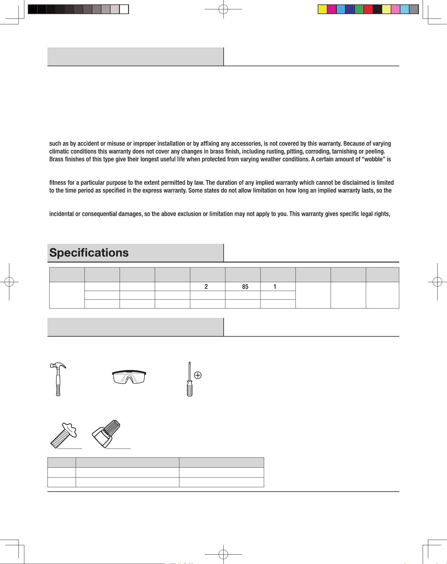
TOOLS REQUIRED
Claw
hammer
Safety
goggles
Phillips
screwdriver
HARDWARE INCLUDED
AA BB
Part Description Quantity
AA Machine Screws 16
BB Wire Nuts 3
THD_RH5H1_UD42.eg 18年11月07日 下午15:20
5.4 kg 1.0
4
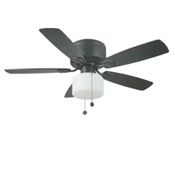
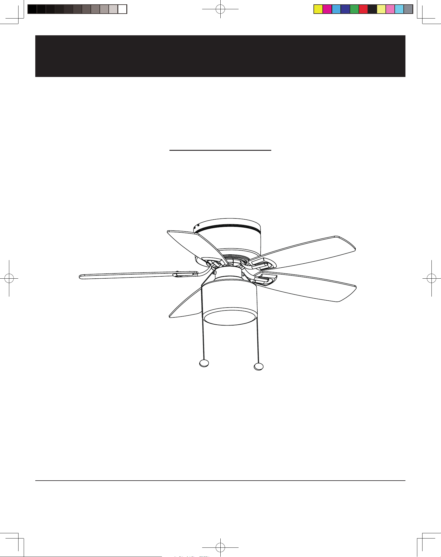
Pre-Installation (continued)
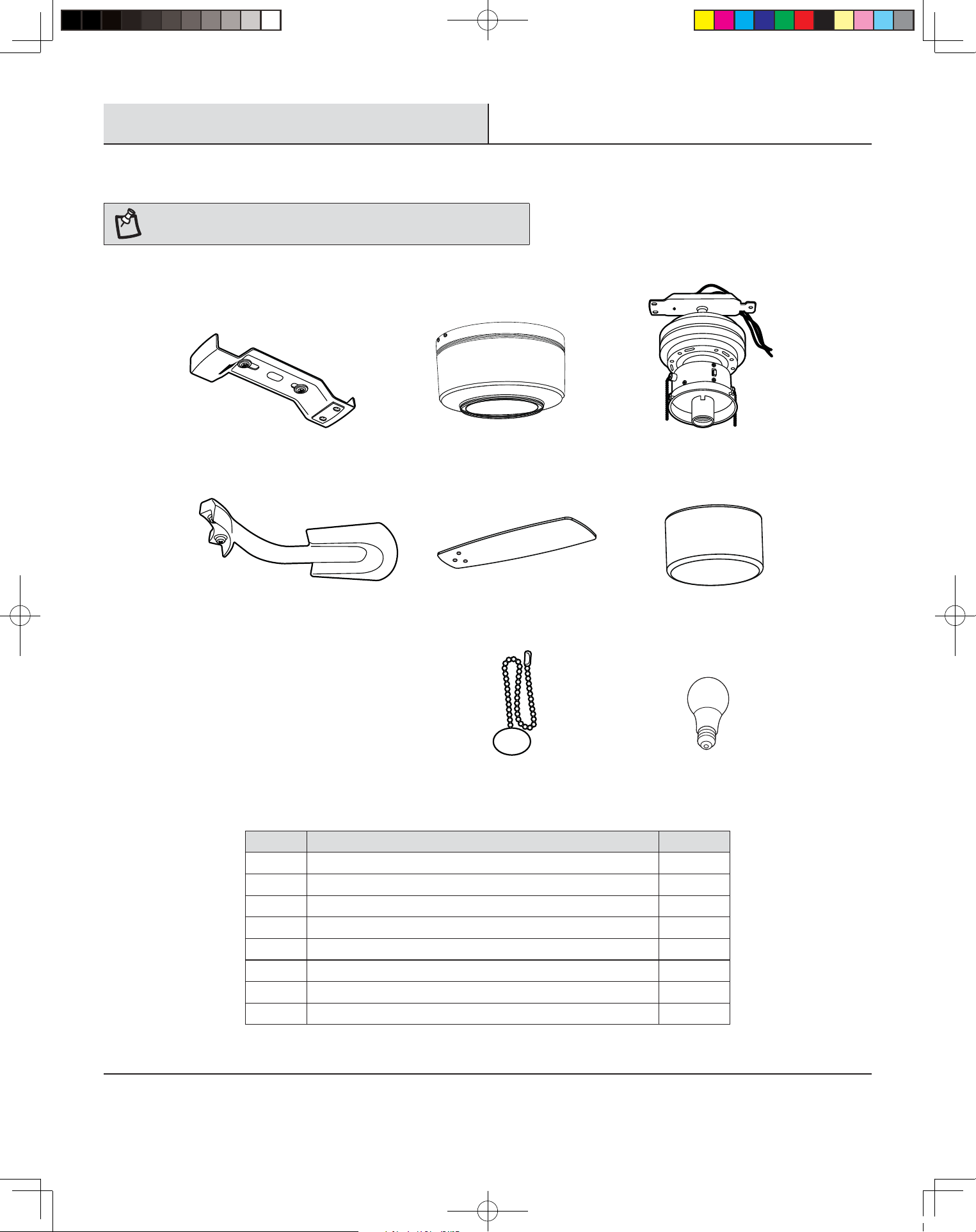
PACKAGE CONTENTS
NOTE: Unpack your fan and check the contents. You should have the
following items listed below
BAC
D
E
F
GH
Part Description Quantity
A Supporting bar 1
B Motor housing 1
C Fan motor with switch housing 1
D Set of blade holders (with blade holder screws pre-installed) 5
E Set of blades 5
F Glass shade 1
G Pull chain pendant 2
H 9 Watt E-26 (LED, A19) Bulb 1
THD_RH5H1_UD42.eg 18年11月07日 下午15:20
5
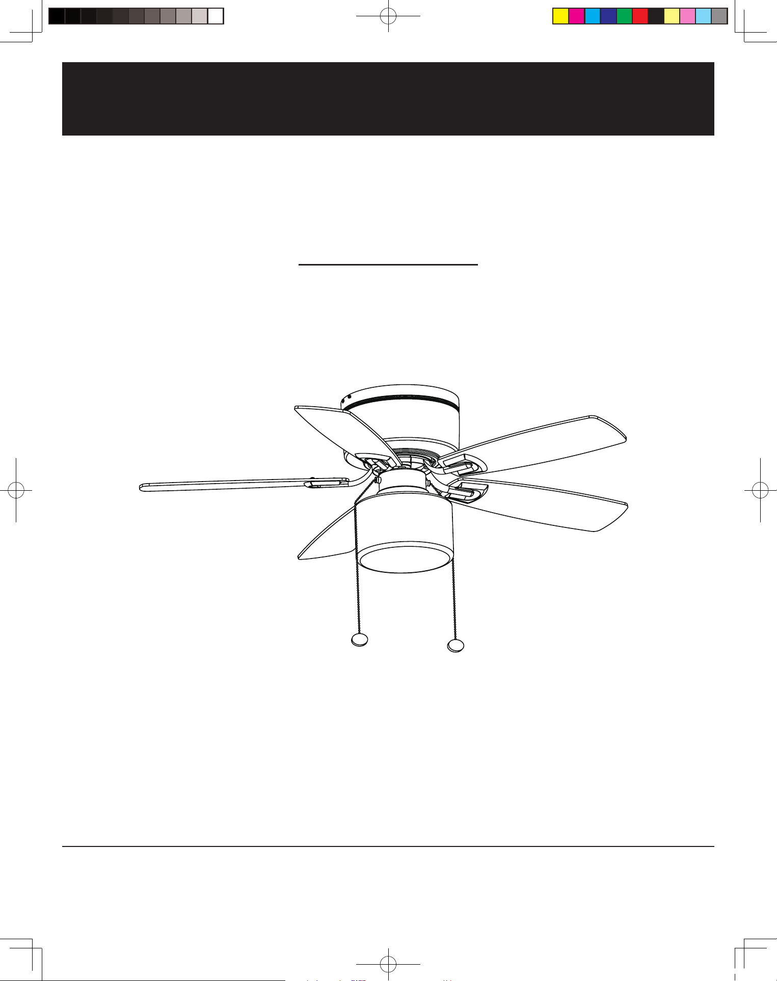
Installation
1
Determining mounting method
WARNING: To reduce the risk of re, electric shock, or
personal injury, mount to outlet box marked acceptable for
fan support of 15.9 Kg (35 lbs) or less and use mounting
screws provided with the outlet box.
□ If there is not an existing UL Listed metal mounting box,
then read the following instructions. Disconnect the power
by removing fuses or turning off circuit breakers.
□ Secure the outlet box directly to the building structure. Use
appropriate fasteners and building materials. The outlet
box and its support must be able to fully support the moving
weight of the fan (at least 35 lbs.). Do not use plastic outlet
boxes. Figures 1 and 2 are examples of different ways to
mount the outlet box.
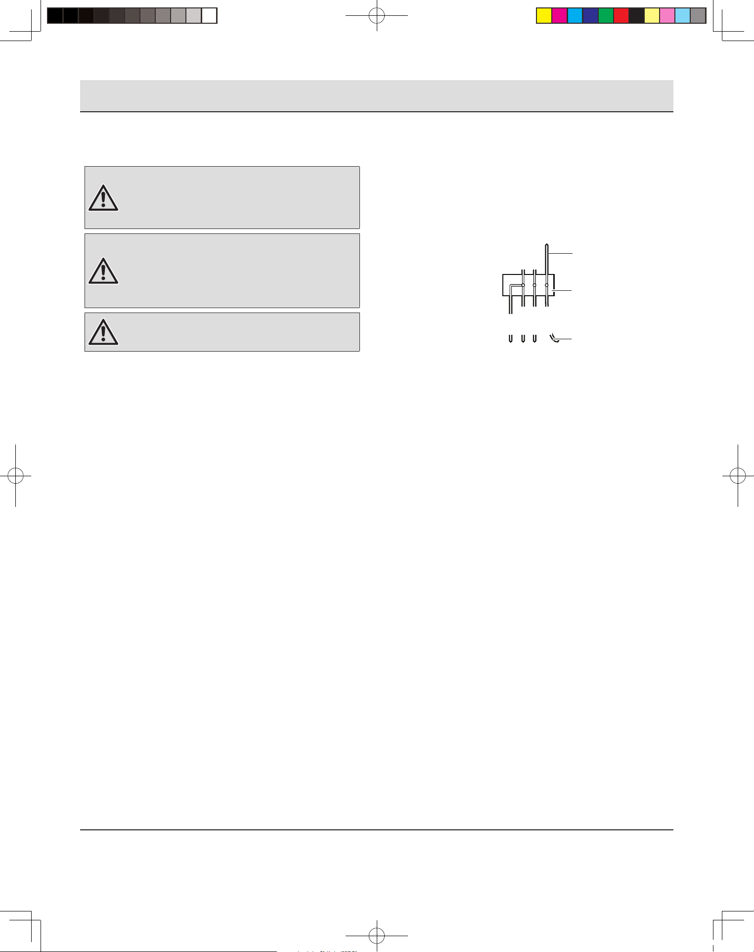
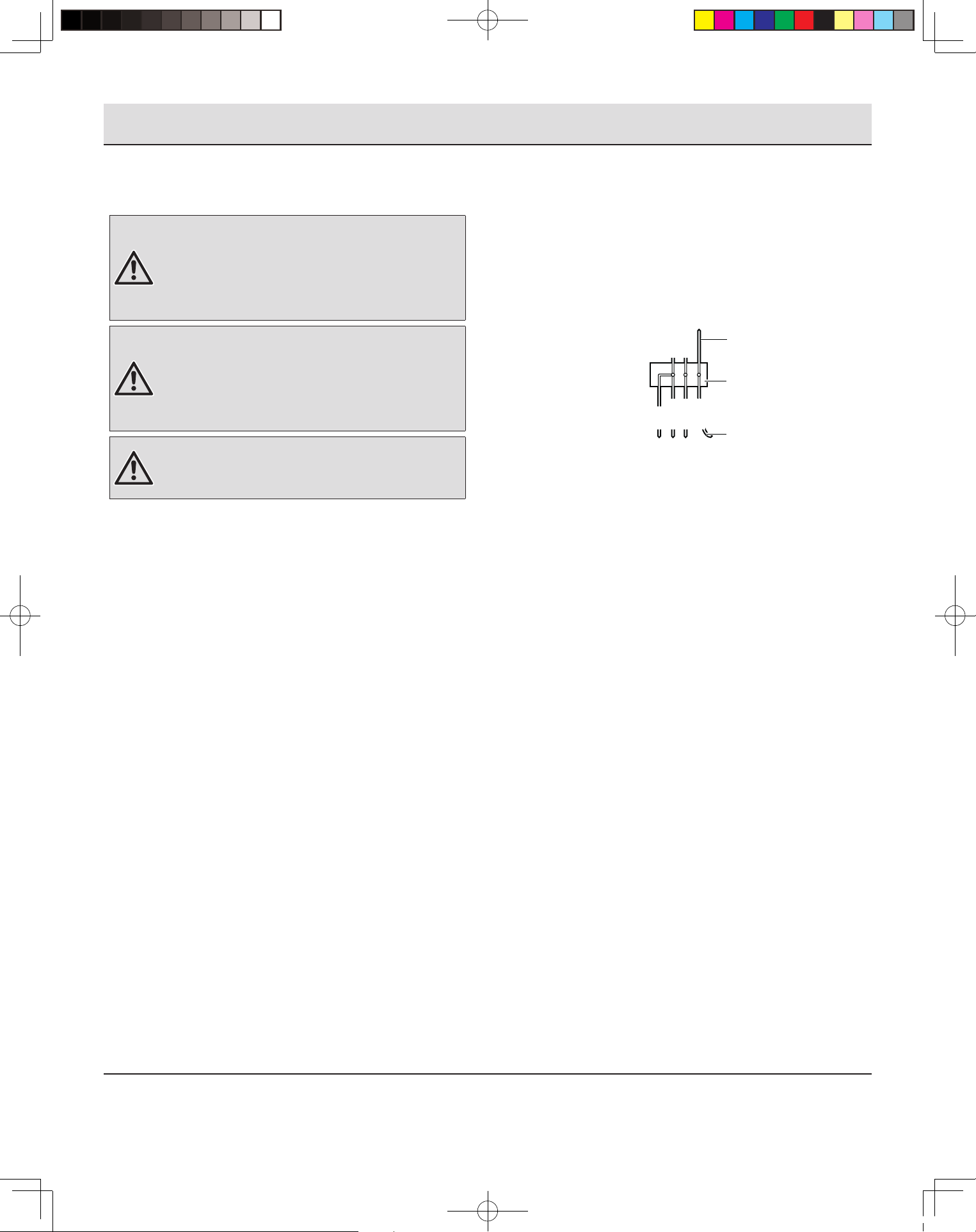
□ To hang your fan where there is an existing xture but no
ceiling joist, you may need an installation hanger bar as
shown in Figure 3 (available at your Retailer).
Figure 1
Figure 2
Figure 3
Outer Box
Outer Box
Outer Box
2
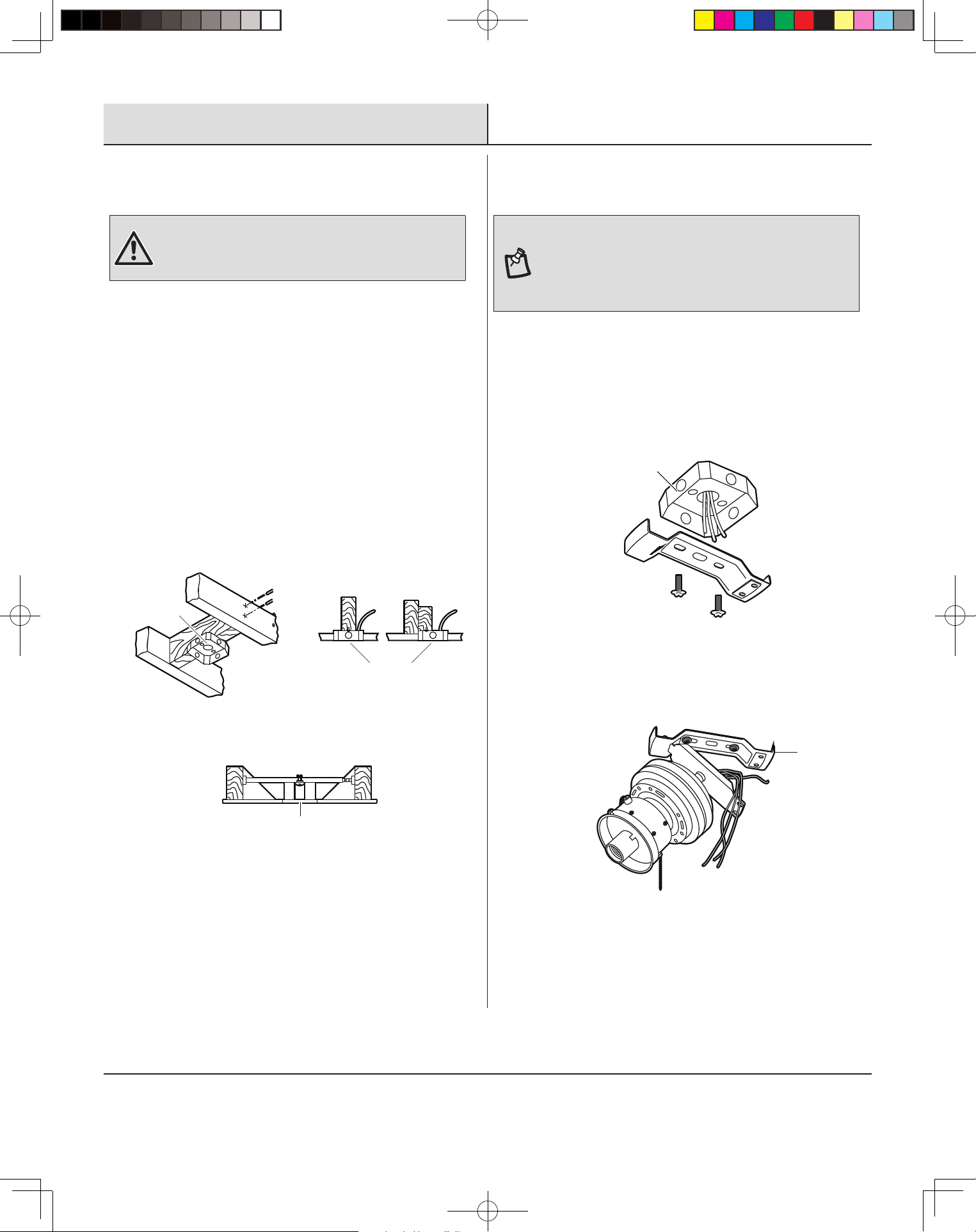
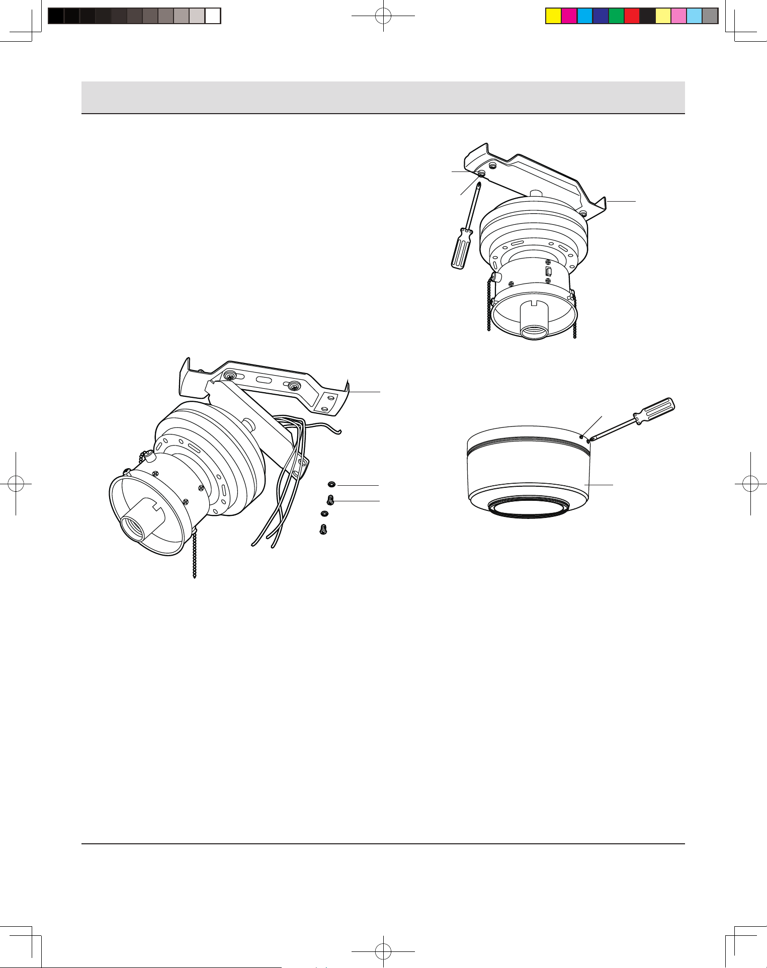
Installing the support bar
NOTE: You may need a longer downrod to maintain proper
blade clearance when installing on a steep, sloped ceiling.
The maximum angle allowable is 18° away from horizontal. If
the canopy touches the downrod, then remove the decorative
canopy bottom cover (C) and turn the canopy (B) 180° before
attaching the canopy (B) to the mounting bracket (A).
REMEMBER to turn off the power. Follow the steps below to hang
your fan properly.
□ Secure the supporting bar to the ceiling outlet box as
shown in Figure 4 by using two screws and washers (not
provided). Make sure the supporting bar is level. You may
need to insert additional washers (not provided) between
the outlet box and the supporting bar to make it level.
Figure 4
Outer Box
□ Before making the electrical connections, use the square
hole at one end of the supporting bar (A) to hang the fan
motor (Figure 5).
Figure 5
A
THD_RH5H1_UD42.eg 18年11月07日 下午15:20
6
Installation (continued)
3
Making the electrical connections
WARNING: To avoid possible electrical shock, be sure
electricity is turned off at the main fuse box before wiring.
If you are not sure the electrical box and fan are grounded,
contact a licensed electrician for advice. They must be
grounded for safe operation.
WARNING: Each wire nut (wire connector) supplied with
this fan is designed to accept up to one 12 gauge house
wire and two wires from the fan. If you have larger than 12
gauge house wiring or more than one house wire to connect
to the fan wiring, consult an electrician for the proper size
wire nuts to use.
WARNING: Check to see that all connections are tight,
including ground, and that no bare wire is visible at the wire
nuts, except for the ground wire.
If you feel that you do not have enough electrical wiring knowledge
or experience, have your fan installed by a licensed electrician.
Follow the steps below to connect the fan to your household
wiring. Use the plastic wire splice connectors (BB) supplied with
your fan. Secure the connectors with electrical tape. Make sure
there are no loose strands or connections.
□ Connect the fan supply (black) wire and light supply (blue)
wire to the black household wire as shown in Figure 6. Do
not connect the blue wire if the light kit is not used.
□ Connect the neutral fan (white) wire to the white neutral
household wire.
□ Connect the fan ground wires (green) on the supporting bar
and the hanger to the household ground wire.
□ After connecting the wires, secure the wire connectors (BB)
with black electrical tape and spread them apart so that
the green and white wires are on one side of the outlet box
and the black and blue wires are on the other side (i.e.,
grounded conductor on one side and hot wires on the other
side).
□ Turn the wire connectors (BB) upward and push the wiring
into the outlet box.
□ If you choose to install another light kit, it must be a UL
Listed light kit accessory marked suitable for use with this
fan. Follow the instruction packed with the light kit.
SUPPLY CIRCUIT
Figure 6
Diagram indicates light kit wiring.
BlackBlack
White
White
Blue
Green
Ground
Conductor
Outlet Box
Green
Ground Lead
THD_RH5H1_UD42.eg 18年11月07日 下午15:20
7
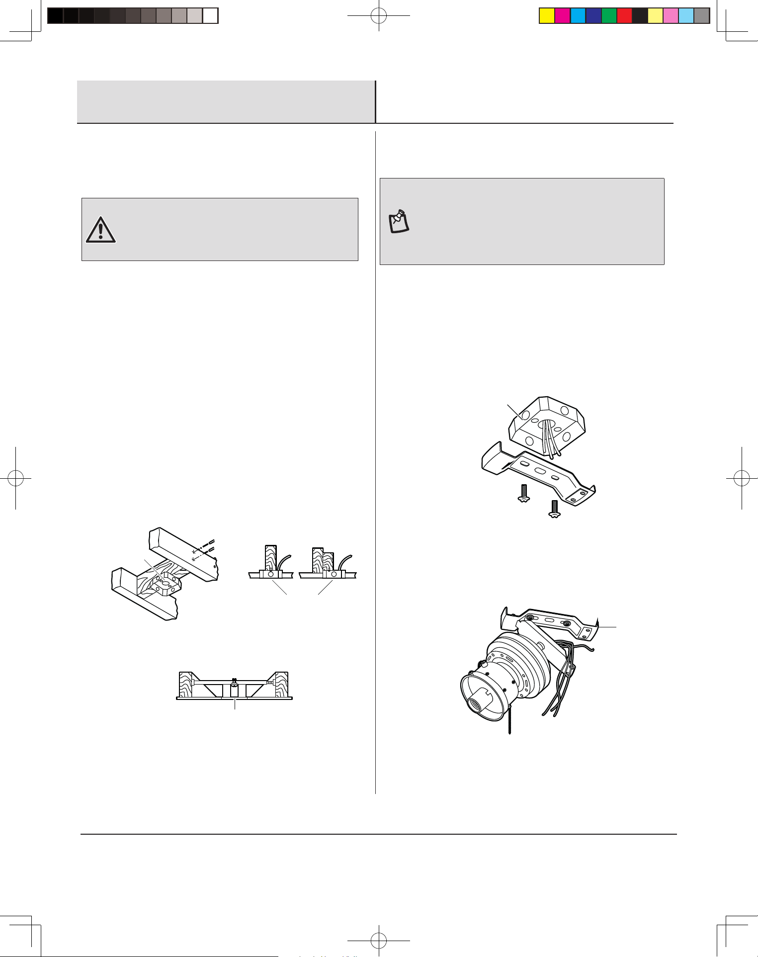
Installation (continued)
4
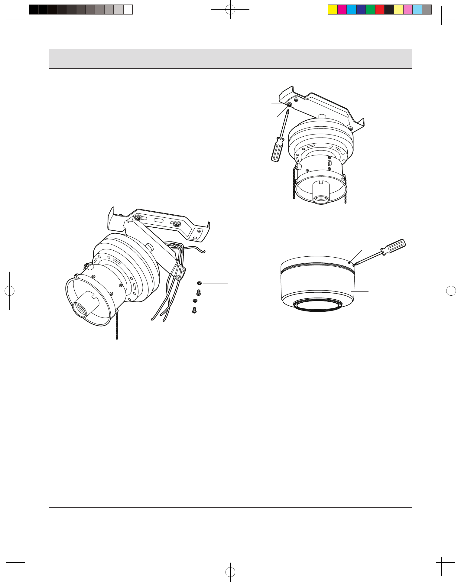
Finishing the installation
□ Match the three holes at two ends of the supporting bar (A)
with three screws of the hanger. Secure the fan assembly
onto the supporting bar (A) using the preassembled screws
(1) and washers (2) (Figure 7 and 8).
□ Fix the motor housing (B) onto the supporting bar (A) by
tightening the four screws (3) preassembled to the motor
housing (B) (Figure 9).
□ Attach the fan pull chain pendant to the pull chain on the
switch assembly.
Figure 7
A
1
2
Figure 8
A
2
1
Figure 9
THD_RH5H1_UD42.eg 18年11月07日 下午15:20
3
B
8
Installation (continued)
5
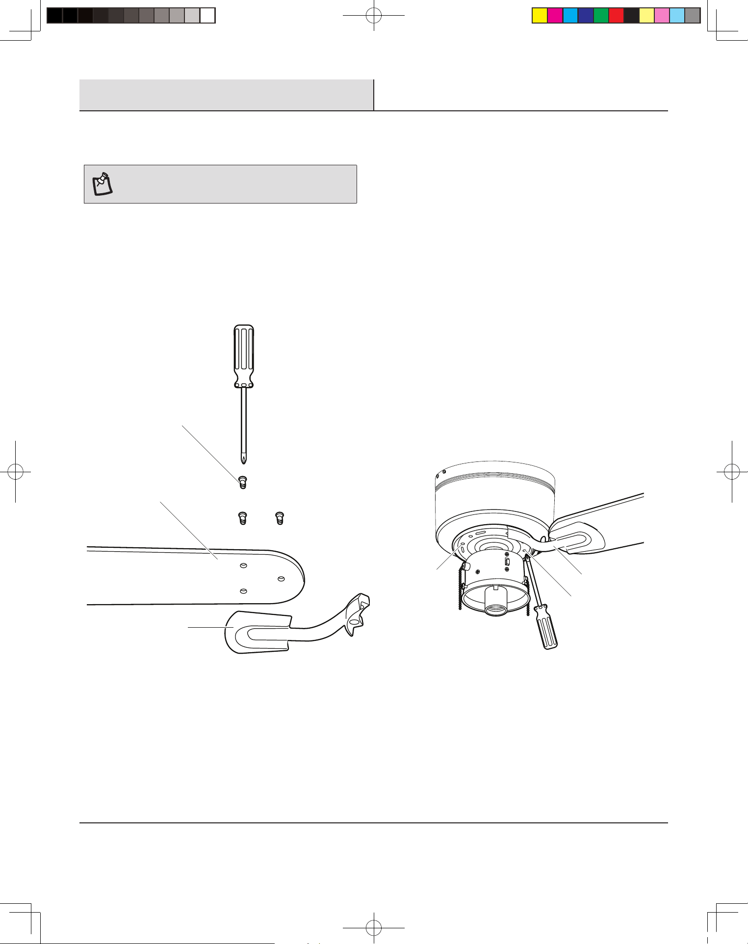
Attaching the fan blades
NOTE: Your fan blades are reversible. Select the blade side
nish which best accentuates your decor. Failure to follow
above procedure could result in fan wobble.
□ Mount the blade holders (D) to the fan blades (E) using the
screws (1) provided – 3 per blade (Figure 10). Please note
the rubber washers are pre-attached to the blade holder
(D).
The fan blade assemblies attach to the motor using the blade
holder screws (2) that are pre-installed into the blade holder (D).
The procedure to attach blade assemblies is as follows:
Figure 10
1
D
E
□ Position the blade holder (D) under the motor such that the
alignment post on the blade holder ts into the slot (3) in
the motor (Figure 11).
□ Tighten the pre-installed blade holder screws (2).
□ Repeat these steps to install the remaining blade
assemblies.
Figure 11
3
2
D
THD_RH5H1_UD42.eg 18年11月07日 下午15:20
9
Installation (continued)
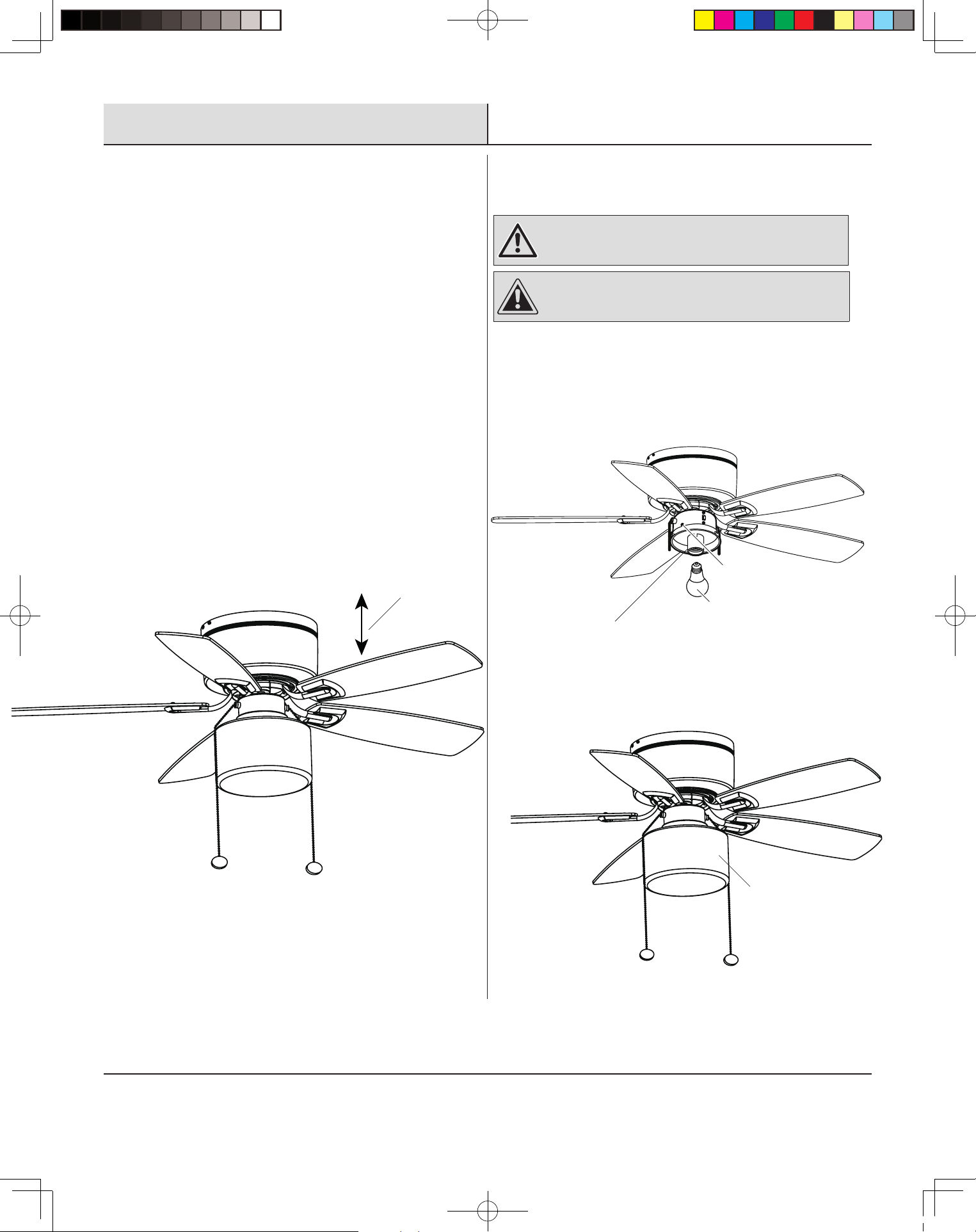
Balancing the blades
All blades are grouped by weight. Because natural woods vary in
density, the fan may wobble even though the blades are weight
matched.
The following procedure should correct most fan wobble. Check for
wobble after each step.
Ƒ Check that all blade and blade holder screws are secure.
Ƒ Most fan wobble problems are caused when blade levels
are unequal. Check this level by selecting a point on the
ceiling above the tip of one of the blades. Measure this
distance as shown in Figure 12. Rotate the fan until the
next blade is positioned for measurement. Repeat for each
blade. Measurements should be within 1/8 in.
Ƒ If blade wobble is still noticeable, interchanging two
adjacent (side by side) blades can redistribute the weight
and possibly result in smoother operation.
Figure 12
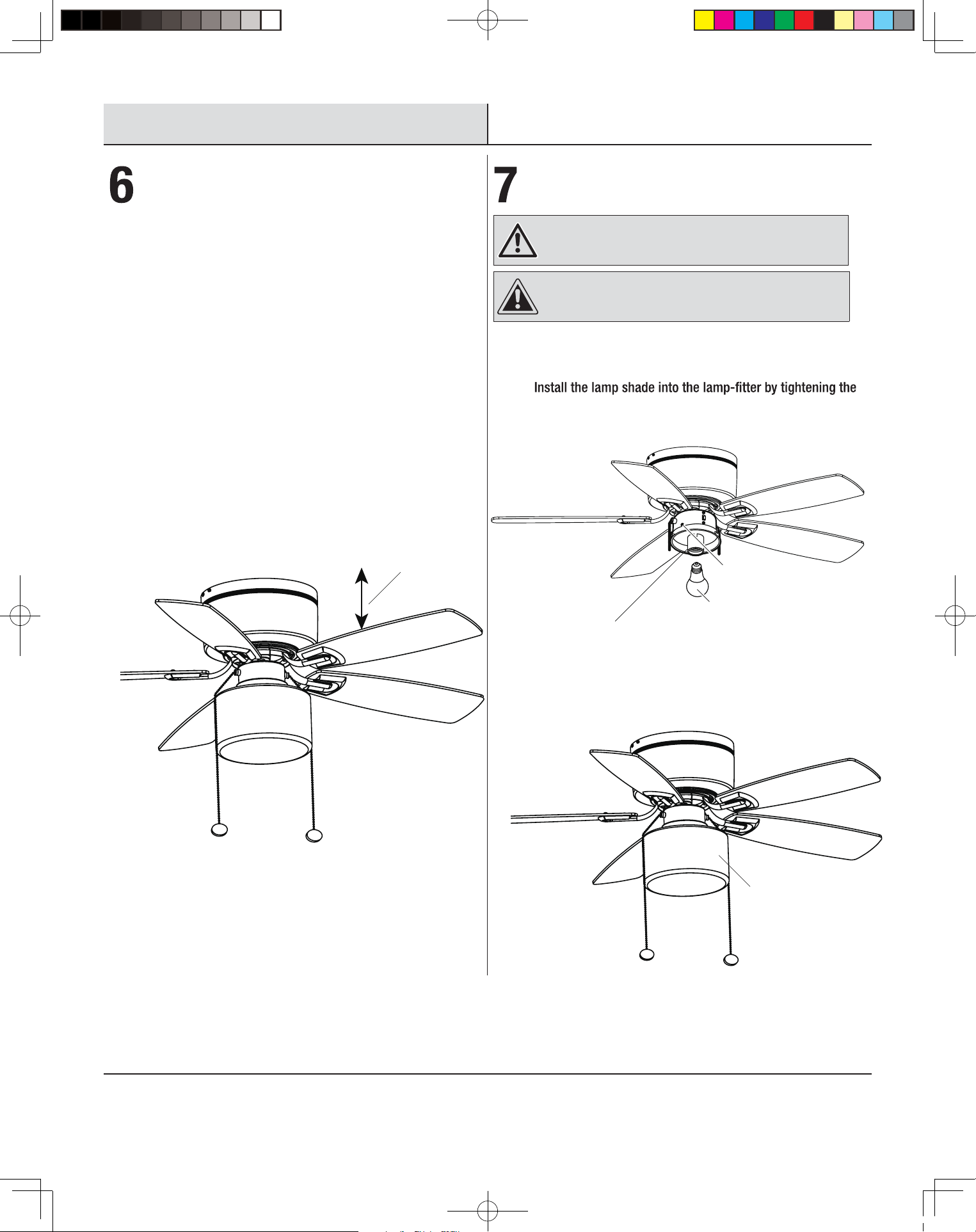
Installing the light kit
WARNING: To reduce the risk of electric shock,
disconnect the electrical supply circuit to the fan before
installing light kit.
CAUTION: Do not use pliers or screwdrivers to tighten
the thumb screws. Overtightening of the thumb screws may
crack the lamp shades.
Install a LED bulb (max. 9W, medium screw base) to the Ƒ
lampholder (Figure 13).
Ƒ
thumb screws (Figure 14).
THD_RH5H1_UD42.eg 18年11月07日 下午15:20
Touch Ceiling
Figure 13
1
LED Bulb
Lamp Holder
Figure 14
F
10
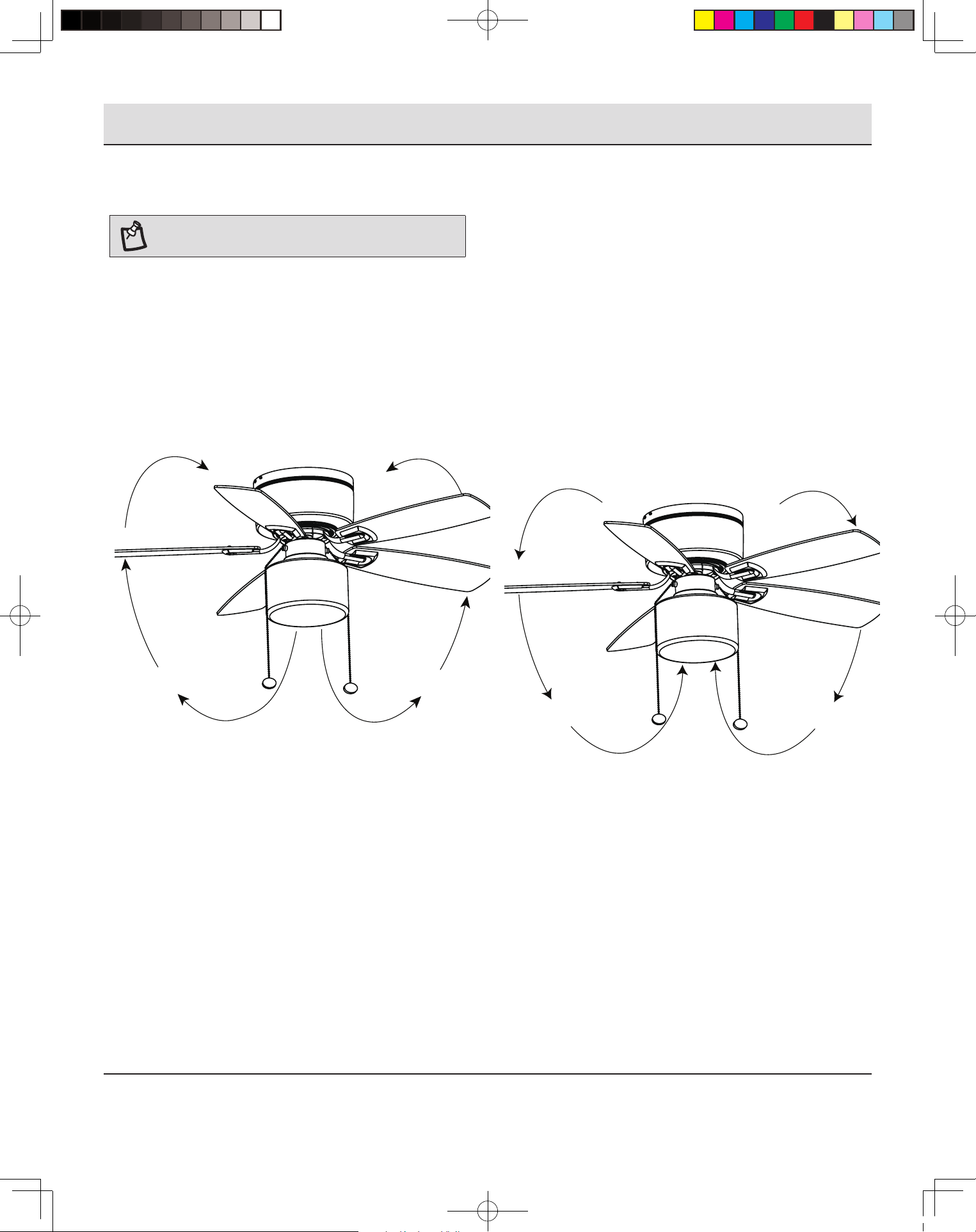
Operation
Operating
NOTE: Wait for the fan to stop before changing the setting
of the slide switch.
The pull chain controls the fan speed as follows: 1 pull – High, 2
pulls – Medium, 3 pulls – Low, and 4 pulls – Off.
Speed settings for warm or cool weather depend on factors such
as the room size, ceiling height, number of fans, and so on.
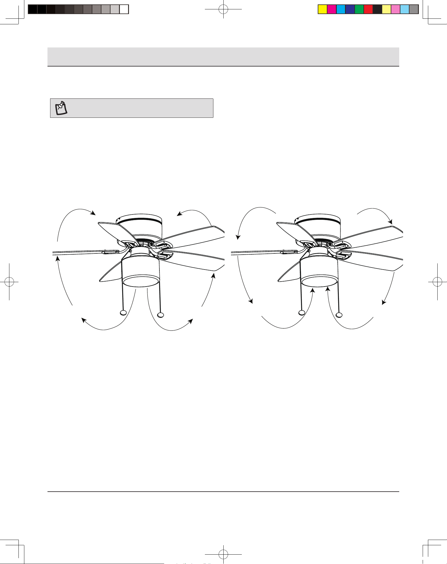
The slide switch controls direction: forward (switch down) or
reverse (switch up).*
Warm weather – (Forward) A downward airow creates a cooling
effect as shown in Figure 15. This allows you to set your air
conditioner on a higher setting without affecting your comfort.
Cool weather – (Reverse) An upward airow moves warm air off
the ceiling area as shown in Figure 16. This allows you to set your
heating unit on a lower setting without affecting your comfort.
THD_RH5H1_UD42.eg 18年11月07日 下午15:20
Figure 15
Figure 16
11
Care and Cleaning
WARNING: Make sure the power is off at the electrical panel box before you attempt any repairs. Refer to the section Making Electrical
Connections Section.
Here are some suggestions to help you maintain your fan.
□ Because of the fan’s natural movement, some connections may become loose. Check the support connections, brackets, and blade
attachments twice a year. Make sure they are secure. (It is not necessary to remove the fan from the ceiling.)
□ Clean your fan periodically to help maintain its new appearance over the years. Use only a soft brush or lint-free cloth to avoid
scratching the nish. The plating is sealed with a lacquer to minimize discoloration or tarnishing. Do not use water when cleaning. This
could damage the motor, or the wood, or possibly cause an electrical shock.
□ You can apply a light coat of furniture polish to the wood blades for additional protection and enhanced beauty. Cover small scratches
with a light application of shoe polish.
□ There is no need to oil your fan. The motor has permanently lubricated bearings.
Troubleshooting
WARNING: Make sure the power is off at the electrical panel box before you attempt any repairs. Refer to the section Making Electrical
Connections Section.
Problem Solution
The fan will not start. □ Check circuit fuses or breakers.
□ Check the line wire connections to the fan and switch wire connections in the switch housing.
The fan sounds noisy. □ Make sure all motor housing screws are snug.
□ Make sure the screws that attach the fan blade bracket to the motor hub are tight.
□ Make sure wire nut connections are not rubbing against each other or the interior wall of the switch
housing.
□ Allow a 24-hour “breaking-in” period. Most noises associated with a new fan disappear during this time.
□ Some fan motors are sensitive to signals from solid-state variable speed controls. If you have installed
this type of control, choose and install another type of control.
□ Make sure the motor housing is a short distance from the ceiling. It should not touch the ceiling.
THD_RH5H1_UD42.eg 18年11月07日 下午15:20
An electronic copy of this user manual can also be obtained online at
homedepot.com
Retain this manual for future use.
THD_RH5H1_UD42.eg 18年11月07日 下午15:20
GUÍA DE USO Y CUIDADO
VENTILADOR DE TECHO DE 42 PULG.
Núm. de modelo RH5H1-ORB/RH5H1-BN
THD_RH5H1_UD42.spa 18年11月07 日 15:22
Puede obtener también una copia electrónica de este manual del usuario en línea en
homedepot.com.
2
Tabla de contenido
Tabla de contenido ..................................2
Información de seguridad .............................2
Garantía ...........................................3
Pre-instalación .....................................4
Operación ........................................10
Cuidado y limpieza .................................11
Resolución de fallas ................................11
Información de seguridad
POR FAVOR LEA Y GUARDE ESTAS INSTRUCCIONES.
1. Para reducir el riesgo de choque eléctrico, antes de comenzar
asegúrese de que la electricidad haya sido desconectada en el
interruptor de circuito o la caja de fusibles.
2. Todo el cableado debe estar de acuerdo con el Código Eléctrico
Nacional, ANSI/NFPA 70 y los códigos eléctricos nacionales.
La instalación eléctrica debe ser hecha por un electricista
calicado autorizado.
3. La caja de salida y la estructura de soporte deben estar
montadas con seguridad y ser capaces de soportar de manera
able un mínimo de 35 libras. Use solamente cajas de salida
listadas UL marcadas “PARA SOPORTE DE VENTILADOR.”
4. No opere el interruptor de reversa mientras las aspas del
ventilador estén en movimiento. El ventilador debe estar
apagado y las aspas detenidas antes de invertir la dirección de
las aspas.
5. Evite colocar objetos en el paso de las aspas. Para evitar
lesiones personales o daños al ventilador y otros artículos, tenga
precaución cuando trabaje cerca o limpie el ventilador.
6. No use agua o detergentes cuando limpie el ventilador o las
aspas. Un paño seco o ligeramente empapado será adecuado
para la mayoría de limipiezas.
7. Después de hacer conexiones eléctricas, los conductores
empalmados deben ser girados hacia arriba y empujados con
cuidado hacia adentro de la caja de salida. El cable debe estar
separado con el conductor de puesta a tierra y el conductor
de puesta a tierra del equipo en un lado de la caja de salida.
Después de hacer los empalmes, estos deben ser girados hacia
arriba y empujados con cuidado hacia adentro de la caja de
salida.
8. Los diagramas eléctricos son solamente para referencia. Los
juegos de lámparas que no están empacados con el ventilador
deben ser Listados UL y marcados como adecuados para uso
con el ventilador modelo que está instalando. Los interruptores
deben ser Interruptores de Uso General UL. Consulte las
instrucciones que vienen con los juegos de lámparas e
interruptores para un montaje apropiado.
ADVERTENCIA: Antes de darle servicio o limpiar la unidad,
desconecte la energía en el panel de servicio y cierre el
servicio desconectando los medios para evitar que la energía
se active accidentalmente. Cuando los medios de desconexión
del servicio no se pueden cerrar, coloque con seguridad una
advertencia fácil de ver.
ADVERTENCIA: Para evitar el riesgo de incendio, choque
eléctrico o lesiones a las personas, monte una caja de salida
aceptable para soporte del ventilador de 15.9 Kg (35 lbs) o
menos. Use los tornillos de montaje proporcionados con la caja
de salida. La mayoría de cajas de salida usadas comúnmente
como soporte de luminarias no son aceptables para soporte
del ventilador y pueden necesitar ser reemplazadas. Consulte
a un electricista calicado si tiene dudas.
ADVERTENCIA: Para reducir el riesgo de lesiones
personales, no doble los soportes de las aspas cuando instale
los soportes, equilibre las aspas o limpie el ventilador. No
inserte objetos extraños en medio de las aspas del ventilador
en rotación.
ADVERTENCIA: Para reducir el riesgo de incendio o
choque eléctrico, no use este ventilador con ningún dispositivo
de control de velocidad de estado sólido.
PRECAUCIÓN: Para reducir el riesgo de lesiones
personales, el ventilador debe estar montado con un mínimo
de 7 pies de espacio libre desde el borde posterior de las
aspas hasta el piso.
RH5H1
UD42
THD_RH5H1_UD42.spa 18年11月07 日 15:22
3
Garantía
GARANTÍA LIMITADA
LO QUE ESTÁ CUBIERTO
El distribuidor garantiza que el motor del ventilador está libre de defectos en materiales y mano de obra presentes en el momento del envío
de la fábrica por un periodo de vida después de la fecha de compra por el comprador original. El distribuidor también garantiza que todas
las otras piezas del ventilador, excluyendo cualquier aspa de vidrio o acrílico, están libres de defectos en materiales y mano de obra en el
momento del envío de la fábrica por un periodo de un año después de la compra por el comprador original. Aceptamos corregir cualquier
defecto sin cargos o a nuestra discreción reemplazar con un modelo comparable o superior si el producto es devuelto a el distribuidor. Para
obtener el servicio de garantía, debe presentar una copia del recibo como prueba de compra. Todos los costos por retirar o reemplazar el
accesorio, no están cubiertos por la garantía. Debido a las condiciones climáticas variables, esta garantía no cubre ningún cambio en el
acabado de latón, incluyendo herrumbre, picaduras, corrosión, deslustrado o descamación. Los acabados de latón de este tipo dan su vida
útil más larga cuando se protegen de las condiciones climáticas variables. Es normal una cierta cantidad de “bamboleo” y no debe ser
considerado un defecto. El mantenimiento realizado por personas no autorizadas anulará la garantía. No hay otra garantía expresa. Por la
presente, el distribuidor renuncia a cualquier y todas las garantías, incluyendo pero no limitadas a Garantías de comercialización o idoneidad
para un propósito particular en la medida permitida por la ley. La duración de cualquier garantía implícita que no puede ser denegada está
una garantía implícita, por lo tanto las limitaciones anteriores podrían no aplicar a usted. La tienda minorista no será responsable de daños
incidentales, consecuenciales, o daños especiales que surgan de o con respecto al uso o rendimiento del producto excepto como pueda ser
acordado de otra manera por la ley. Algunos estados no permiten la exclusión de los daños incidentales o consecuenciales, por lo tanto, las
otros derechos que varían de un estado a otro. Esta garantía reemplaza todas las garantías anteriores. Los costos de envío por cualquier
devolución de producto como parte de un reclamo sobre la garantía deben ser pagados por el cliente.
E
Tamaño del
ventilador
Velocidad Voltios Amperios Watts RPM pies
3
/min Peso neto Peso bruto C.F.
42 p
lg
Baja 120 N/A
N/A
N/A
12 8 430
4.8 kgMedia 120 28 140 2163
Alta 120 4 180 2737
Pre-instalación
HERRAMIENTAS REQUERIDAS
Martillo de
garra
Gafas de
seguridad
Desarmador
Phillips
HERRAJE INCLUIDO
AA BB
Pieza Descripción Cantidad
AA Tornillos de máquina 16
BB Tuercas de cable 3
THD_RH5H1_UD42.spa 18年11月07 日 15:22
5.4 kg 1.0
4
Pre-instalación (continuación)
CONTENIDO DEL PAQUETE
NOTA: Desempaque su ventilador y compruebe el contenido. Debe tener
los siguientes artículos listados a continuación.
BA C
D
E
F
G
Pieza Descripción Cantidad
A Barra de soporte 1
B Carcasa del motor 1
C Motor del ventilador con carcasa de interruptor 1
D Conjunto de porta aspas (con tornillos de porta aspas preinstalados) 5
E Conjunto de aspas 5
F Pantalla de vidrio 1
G Halador colgante de cadena 2
H
Foco de 9 Watts de base E-26 (LED, A19) 1H
THD_RH5H1_UD42.spa 18年11月07 日 15:22
5
Instalación
1
Determinación del método de
montaje
ADVERTENCIA: Para evitar el riesgo de incendio,
choque eléctrico o lesiones a las personas, monte la caja
de salida marcada aceptable para soporte de ventilador
de 15.9 Kg (35 lbs) o menos y use los tornillos de montaje
proporcionados con la caja de salida.
□ Si no hay una caja de montaje de metal existente Listada
UL, lea las siguientes instrucciones. Desconecte la energía
retirando los fusibles o apagando los interruptores de
circuito.
□ Asegure la caja de salida directamente a la estructura
del edicio. Use sujetadores apropiados y materiales
de construcción. La caja de salida y su soporte deben
de ser capaces de soportar por completo el peso móvil
del ventilador (al menos 35 lbs.) No use cajas de salida
plásticas. Las Figuras 1 y 2 son ejemplos de diferentes
maneras de montar la caja de salida.
□ Para colgar su ventilador donde ya hay una luminaria pero
no una viga de techo, puede necesitar un barra colgador
como se muestra en la Figura 3 (disponible en su tienda
minorista Hampton Bay).
Figura 1
Figura 2
Figura 3
Caja exterior
Caja exterior
Caja exterior
2
Instalación de la barra soporte
NOTA: Puede necesitar un vástago de extensión para
mantener un espacio libre de aspa adecuado cuando instale
sobre un techo inclinado. El ángulo máximo permisible es
de 18° a partir de la horizontal. Si el dosel toca el vástago
de extensión, retire la cubierta decorativa del dosel (C) y gire
el dosel (B) 180° antes de instalar el dosel (B) al soporte de
montaje (A).
RECUERDE desconectar la energía. Siga los pasos a continuación
para colgar su ventilador apropiadamente.
□ Asegura la barra de soporte a la caja de salida del techo
como se muestra en la Figura 4 usando dos tornillos y
arandelas (no suministrados). Asegúrese de que la barra de
soporte esté nivelada. Puede necesitar insertar arandelas
adicionales (no suministradas) entre la caja de salida y la
barra de soporte para nivelar.
Figura 4
Caja exterior
□ Antes de hacer las conexiones eléctricas, use el agujero
cuadrado en un extremo de la barra de soporte (A) para
colgar el motor del ventilador (Figura 5).
Figura 5
A
THD_RH5H1_UD42.spa 18年11月07 日 15:22
6
Instalación (continuación)
3
Cómo hacer las conexiones eléctricas
ADVERTENCIA: Para evitar un posible choque eléctrico,
asegúrese de que la electricidad esté desconectada en
la caja de fusibles principal antes del cableado. Si no
está seguro de que la caja eléctrica y el ventilador están
conectados a tierra, póngase en contacto con un electricista
calicado para que lo aconseje. Deben estar conectados a
tierra para una operación segura.
ADVERTENCIA: Cada tuerca de cable (conector de
cable) suministrada con este ventilador está diseñada
para aceptar hasta un cable calibre 12 y dos cables del
ventilador. Si tiene un cableado más grande de calibre
12 o más de un cableado para conectar al cableado del
ventilador, consulte a un electricista sobre el tamaño
adecuado de las tuercas de cableado que debe usar.
ADVERTENCIA: Revise para ver que todas las
conexiones estén apretadas, incluyendo la tierra, y que
ningún cable desnudo sea visible en las tuercas de
cableado, excepto el cable de tierra.
Si siente que no tiene suciente conocimiento o experiencia sobre
cableado eléctrico, haga que su ventilador sea instalado por un
electricista autorizado.
Siga los pasos a continuación para conectar el ventilador al
cableado eléctrico de su vivienda. Use los conectores plásticos de
empalme de cables (BB) suministrados con su ventilador. Asegure
los conectores con cinta aislante. Asegúrese de que no hayan
hebras o conexiones ojas.
□ Conecte el cable de alimentación del ventilador (negro) y el
cable de alimentación de la lámpara (azul) al cable negro
de la vivienda como se muestra en la Figura 6. No conecte
el cable azul si el juego de la lámpara no es usado.
□ Conecte el cable neutro del ventilador (blanco) al cable
neutro blanco de la vivienda.
□ Conecte los cables de tierra del ventilador (verdes) en la barra
de soporte y el colgador, al cable de tierra de la vivienda.
□ Después de conectar los cables, asegure los conectores de
cable (BB) con cinta aislante negra y sepárelos de modo
que los cables verde y blanco estén en un lado de la caja
de salida y los cables negro y azul en el otro lado. (o sea, el
conector con conexión a tierra en un lado y los cables vivos
en el otro lado).
□ Gire los conectores de cable (BB) hacia arriba y empuje el
cableado dentro de la caja de salida.
□ Si desea instalar otro juego de lámparas, debe ser un
accesorio de juego de lámparas Listado UL marcado como
adecuado para ser usado con este ventilador . Siga las
instrucciones que vienen con el juego de lámparas.
CIRCUITO DE ALIMENTACIÓN
Figura 6
El diagrama indica el cableado del juego de lámparas.
NegroNegro
Blanco
Blanco
Azul
Verde
Conductor
de tierra
Caja de salida
Verde
Ground Lead
YH-
THD_RH5H1_UD42.spa 18年11月07 日 15:22
7
Instalación (continuación)
4
Finalización de la instalación
□ Haga coincidir los tres agujeros en los dos extremos de la
barra de soporte (A) con tres tornillos del colgador. Asegure
el ensamblaje del ventilador sobre la barra de soporte (A)
usando los tornillos preensamblados (1) y arandelas (2)
(Figura 7 y 8).
□ Fije la carcasa del motor (B) sobre la barra de soporte (A)
apretando los cuatro tornillos (3) preensamblados a la
carcasa del motor (B) (Figura 9).
□ Instale el halador colgante de cadena del ventilador a la
cadena de tiro en el ensamblaje del interruptor.
Figura 7
A
1
2
Figura 8
A
2
1
Figura 9
THD_RH5H1_UD42.spa 18年11月07 日 15:22
3
B
8
Instalación (continuación)
5
Instalación de las aspas del
ventilador
NOTA: Las aspas de su ventilador son reversibles.
Seleccione el acabado lateral del aspa que mejor acentúe
su decoración. No seguir el procedimiento anterior puede
resultar en bamboleo del ventilador.
□ Monte los porta aspas (D) a las aspas del ventilador (E)
usando los tornillos (1) proporcionados – 3 por aspa (Figura
10). Note que las arandelas de goma están preinstaladas al
porta aspas (D).
Los ensamblajes de aspas del ventilador se instalan al motor
usando los tornillos del porta aspas (2) que están preinstalados
dentro del porta aspas (D). El procedimiento para instalar los
ensamblajes de aspas es como sigue:
Figura 10
1
D
E
□ Coloque el porta aspas (D) bajo el motor de modo que el
poste de alineamiento en el porta aspas encaje dentro de
la ranura (3) en el motor (Figura 11).
□ Apriete los tornillos preinstalados del porta aspas (2).
□ Repita estos pasos para instalar los ensamblajes de las
aspas restantes.
Figura 11
THD_RH5H1_UD42.spa 18年11月07 日 15:22
3
2
D
9
Instalación (continuación)
6
Cómo equilibrar las aspas
Todas las aspas están agrupadas por peso. Debido a que las
maderas naturales varían en densidad, el ventilador puede
bambolear incluso si las aspas concuerdan en peso.
El siguiente procedimiento debe corregir la mayor parte del
bamboleo del ventilador. Compruebe si hay bamboleo después de
cada paso.
□ Compruebe que todos los tornillos de las aspas y los porta
aspas estén seguros.
□ La mayoria de problemas de bamboleo ocurren cuando los
niveles de las aspas son desiguales. Compruebe este nivel
seleccionando un punto en el techo sobre la punta de una
de las aspas. Mida esta distancia como se muestra en la
Figura 12 . Gire el ventilador hasta que la siguiente aspa
esté ubicada para medición. Repita para cada aspa. Las
medidas deben estar dentro de 1/8 pulg.
□ Si todavía se nota bamboleo en el aspa, el intercambio de dos
aspas adyacentes (lado por lado) puede redistribuir el peso y
posiblemente resulte en un funcionamiento más estable.
Figura
12
Tocar techo
7
Instalación del juego de lámparas
ADVERTENCIA: Para reducir el riesgo de choque
eléctrico, desconecte el circuito de suministro eléctrico al
ventilador antes de instalar el juego de lámparas.
PRECAUCIÓN: No use tenazas o destornilladores
para apretar los tornillos de pulgar. Apretar en exceso los
tornillos de pulgar puede rajar las pantallas de la lámpara.
Instale una bombilla (máx. 9W, LED, base de tornillo □
mediano) al portalámpara (Figura 13 ).
□ Instale la pantalla de la lámpara en el adaptador de la
lámpara apretando los tornillos de pulgar (Figura 14).
Figura 13
Bombilla
Portalámpara
Figura 14
THD_RH5H1_UD42.spa 18年11月07 日 15:22
1
F
10
Operación
Cómo operarla
NOTA: Espere a que el ventilador se detenga antes de
cambiar el ajuste del interruptor corredizo.
La cadena controla la velocidad del ventilador como sigue: 1 tirón–
Alta, 2 tirones– Media, 3 tirones– Baja, y 4 tirones– Apagado.
Los ajustes de velocidad para clima cálido o fresco dependen de
factores como el tamaño de la habitación, altura del techo, número
de ventiladores, y así sucesivamente.
Figura 15
El interruptor corredizo controla la dirección: hacia adelante
(interruptor abajo) o reversa (interruptor hacia arriba)*.
Clima cálido – (Hacia adelante) Un ujo de aire hacia abajo crea un
efecto de enfriamiento como se muestra en la Figura 15. Esto le
permite ajustar su acondicionador de aire a un ajuste más alto sin
afectar su comodidad.
Clima fresco– (Reversa) Una corriente de aire hacia arriba hace
salir el aire caliente del área del techo como se muestra en la
Figura 16. Esto le permite ajustar su unidad de calefacción a un
ajuste más bajo sin afectar su comodidad.
Figura 16
THD_RH5H1_UD42.spa 18年11月07 日 15:22

11
Cuidado y limpieza
ADVERTENCIA: Asegúrese de que la energía esté desconectada en la caja del panel eléctrico antes de intentar cualquier reparación.
Consulte la sección Cómo hacer conexiones eléctricas.
Aquí tiene algunas sugerencias para ayudarle a mantener su ventilador.
□ Debido al movimiento natural del ventilador, algunas conexiones se pueden aojar. Revise las conexiones del soporte, soportes y
acoplamientos de las aspas dos veces al año. Asegúrese de que estén seguras. (No es necesario retirar el ventilador del techo.)
□ Limpie su ventilador periódicamente para ayudar a mantener su apariencia nueva con el paso de los años. Use solamente un cepillo
suave o paño sin pelusa para evitar rayar el acabado. El enchapado está sellado con una laca para minimizar la decoloración o el
deslustrado. No use agua cuando limpie. Esto podría dañar el motor, o la madera, o causar posiblemente un choque eléctrico.
□ Puede aplicar una capa ligera de cera para muebles a las aspas de madera para protección adicional y belleza mejorada. Cubra las
rayas pequeñas con una aplicación ligera de betún para calzado.
□ No hay necesidad de aceitar su ventilador. El motor tiene cojinetes lubricados permanentemente.
Resolución de fallas
ADVERTENCIA: Asegúrese de que la energía esté desconectada en la caja del panel eléctrico antes de intentar cualquier reparación.
Consulte la sección Cómo hacer conexiones eléctricas.
Problema Solución
El ventilador no arranca. □ Revise los fusibles o los interruptores.
□ Revise las conexiones del cable de línea al ventilador y las conexiones del cable del interruptor en la
carcasa del interruptor.
El ventilador hace ruido. □ Asegúrese de que todos los tornillos de la carcasa del motor estén ajustados.
□ Asegúrese de que los tornillos que sujetan el soporte del aspa del ventilador al núcleo del motor estén
apretados.
□ Asegúrese de que las conexiones de la tuerca del cable no rocen entre sí o con la pared interior de la
carcasa del interruptor.
□ Permita un periodo de “rodaje” de 24 horas. La mayoría de ruidos asociados a un ventilador nuevo
desaparecen durante este tiempo.
□ Algunos motores de ventilador son sensibles a señales de controles de velocidad variable de estado
sólido. Si tiene instalado este tipo de control, elija e instale otro tipo de control.
□ Asegúrese de que la carcasa del motor esté a una corta distancia del techo. No debe tocar el techo.
THD_RH5H1_UD42.spa 18年11月07 日 15:22
Conserve este manual para uso futuro.
Puede obtener también una copia electrónica de este manual del usuario en línea en
homedepot.com.
THD_RH5H1_UD42.spa 18年11月07 日 15:22