3
21
13
20
14
7
21
23
10
4
15
12
15
11
6
15
14
8
9
3x
8x
4x
4x
2x
2x
4x
4x
3 5 6 7
13 14 20 21
1
3x
5
4x
19
4 8 10 11
12 14 15
2
19
16
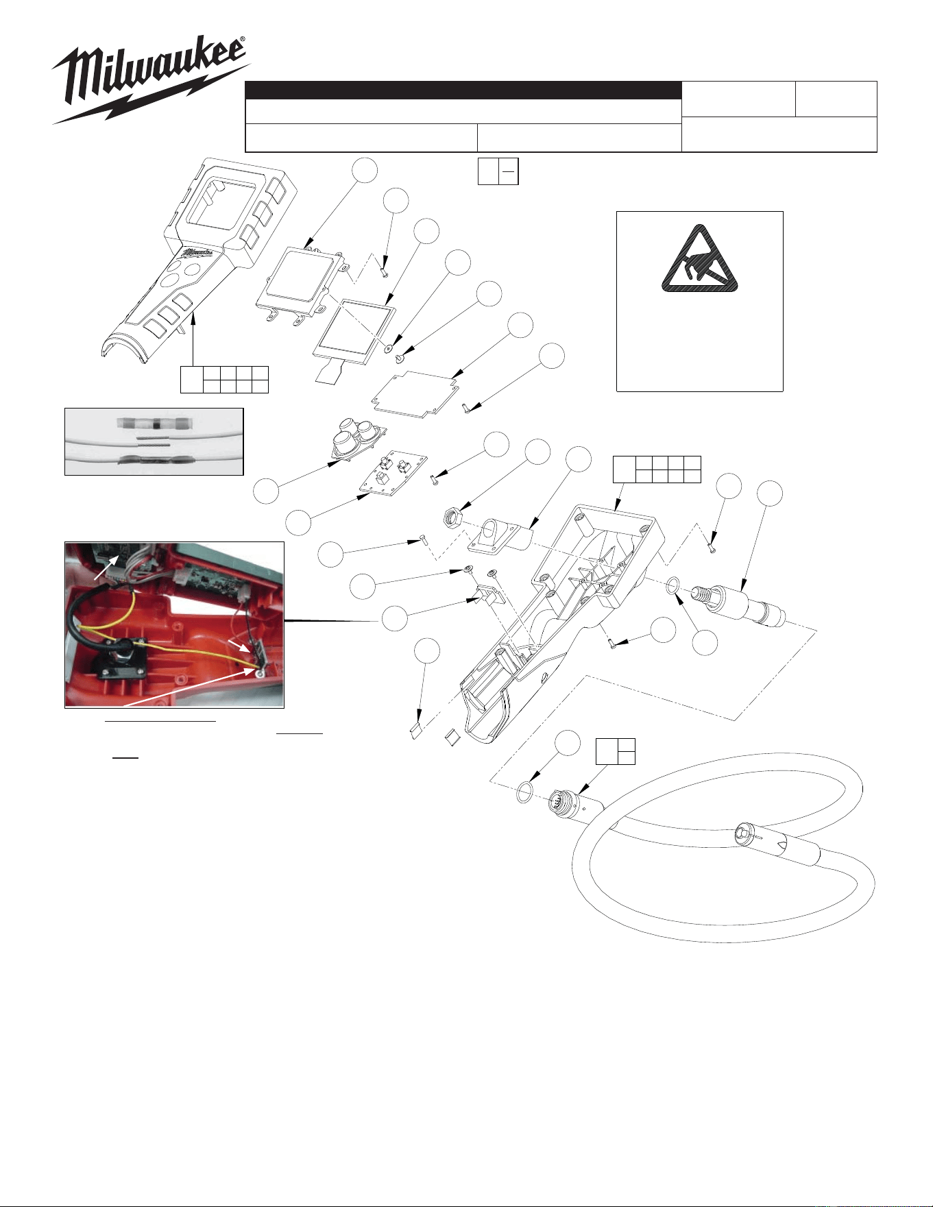
2310-21
12 VOLT DIGITAL INSPECTION CAMERA
Sept. 2008
FIG. PART NO. DESCRIPTION OF PART NO. REQ.
1 14-46-1870 12 Volt Top Housing Kit (1)
2 14-46-1880 12 Volt Bottom Housing Kit (1)
3 44-06-0050 LCD Lens (1)
4 --------------- Holder (1)
5 42-42-0305 Rubber Button (1)
6 22-09-1460 PCB - Switch (1)
7 --------------- PCB - Main (1)
8 22-09-1480 PCB - Battery Contact (See Note) (1)
9 42-70-0180 Clip (2)
10 --------------- M10 Hex Head Nut (1)
11 --------------- O-Ring (1)
12 --------------- Socket Assembly (1)
13 --------------- LCD (1)
14 05-78-0840 M2 x 4 Washer Hd Self-Tapping Scr (5)
15 05-78-0850 M2.6 x 10 Self-Tapping Screw (12)
16 48-53-0115 Camera Cable (1)
19 34-40-0195 O-Ring (1)
20 45-88-0665 LCD Cushion Washer (3)
21 05-78-0085 M2 x 6 Screw (12)
23 05-78-0090 M2 x 5 Screw (4)
12-20-0705 Service Nameplate (Not Shown) (1)
42-55-0460 Carrying Case (Not Shown) (1)
54-07-2310
REVISED BULLETIN
SERVICE PARTS LIST
BULLETIN NO.
WIRING INSTRUCTION
DATE
CATALOG NO.
SPECIFY CATALOG NO. AND SERIAL NO. WHEN ORDERING PARTS
SERIAL
NUMBER
MILWAUKEE ELECTRIC TOOL CORPORATION
13135 W. LISBON RD., BROOKFIELD, WI 53005
Drwg. 3
EXAMPLE:
Component Parts (Small #) Are Included
When Ordering The Assembly (Large #).
0
00
B47A
ATTENTION
OBSERVE PRECAUTIONS
FOR HANDLING
ELECTROSTATIC
SENSITIVE
DEVICES
Clip
Clip
Clip and remove
yellow wire
NOTE: Service replacement PCB-Battery Contact
22-09-1480 will have a Yellow leadwire soldered onto the
PCB Board next to the black wire; Loose end of the Yellow
leadwire must be spliced into the existing Yellow leadwire of
Main PCB Board.
PCB-
Main
PCB-
Battery Contact
A Solder Sleeve Wire Splice
Connector is recommended
when splicing the two Yellow
PCB-Battery Contact leadwires.