
1
2
3
2
44
47
38
30
39
7
8 9 10
11 12
28
10 13 14 15 17 18 20 21
22 23 24 25 26 27 45
49
1
5
MILWAUKEE ELECTRIC TOOL CORPORATION
13135 W. Lisbon Road, Brookfi eld, WI 53005
Drwg. 1
BULLETIN NO.
54-26-2463
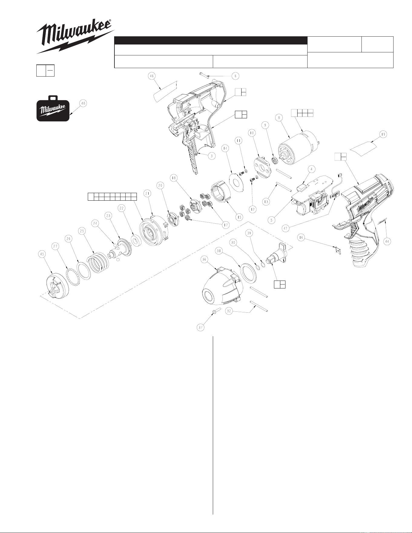
SERVICE PARTS LIST
FIG. PART NO. DESCRIPTION OF PART NO. REQ.
1 31-50-2403 Handle Set (1)
2 --------------- Left Handle Half (1)
3 --------------- Right Handle Half (1)
4 45-24-0105 Fwd./Rev. Button (1)
5 23-66-1132 Electronics Module Assembly (1)
6 06-82-2385 M2.6 x 14 T-9 Screw (5)
7 23-30-0090 Motor Service Assembly (1)
8 --------------- Motor (1)
9 --------------- Pinion (1)
10 --------------- Motor Mount (1)
11 --------------- Washer (2)
12 --------------- M3 x 6 Screw (2)
13 06-65-0075 Pin (2)
14 --------------- Washer (1)
15 --------------- Ring Gear (1)
16 42-70-0055 Clip (1)
17 --------------- Planet Gear Set (8)
18 --------------- Sun Gear (1)
19 10-20-0790 Warning Label (1)
20 --------------- Carriage (1)
21 --------------- Rear Housing (1)
22 --------------- Ball Bearing (1)
23 --------------- Cam Shaft (1)
24 --------------- 3/16" Dia. Steel Ball (2)
25 --------------- Compression Spring (1)
26 --------------- Washer (1)
27 --------------- 3.0mm Dia. Steel Ball (29)
28 14-29-0190 Gear Assembly (1)
CATALOG NO. 2451-20
REVISED BULLETIN
SPECIFY CATALOG NO. AND SERIAL NO. WHEN ORDERING PARTS
12 Volt 3/8" Square Drive Impact Wrench
STARTING
SERIAL NO.
DATE
Mar. 2013
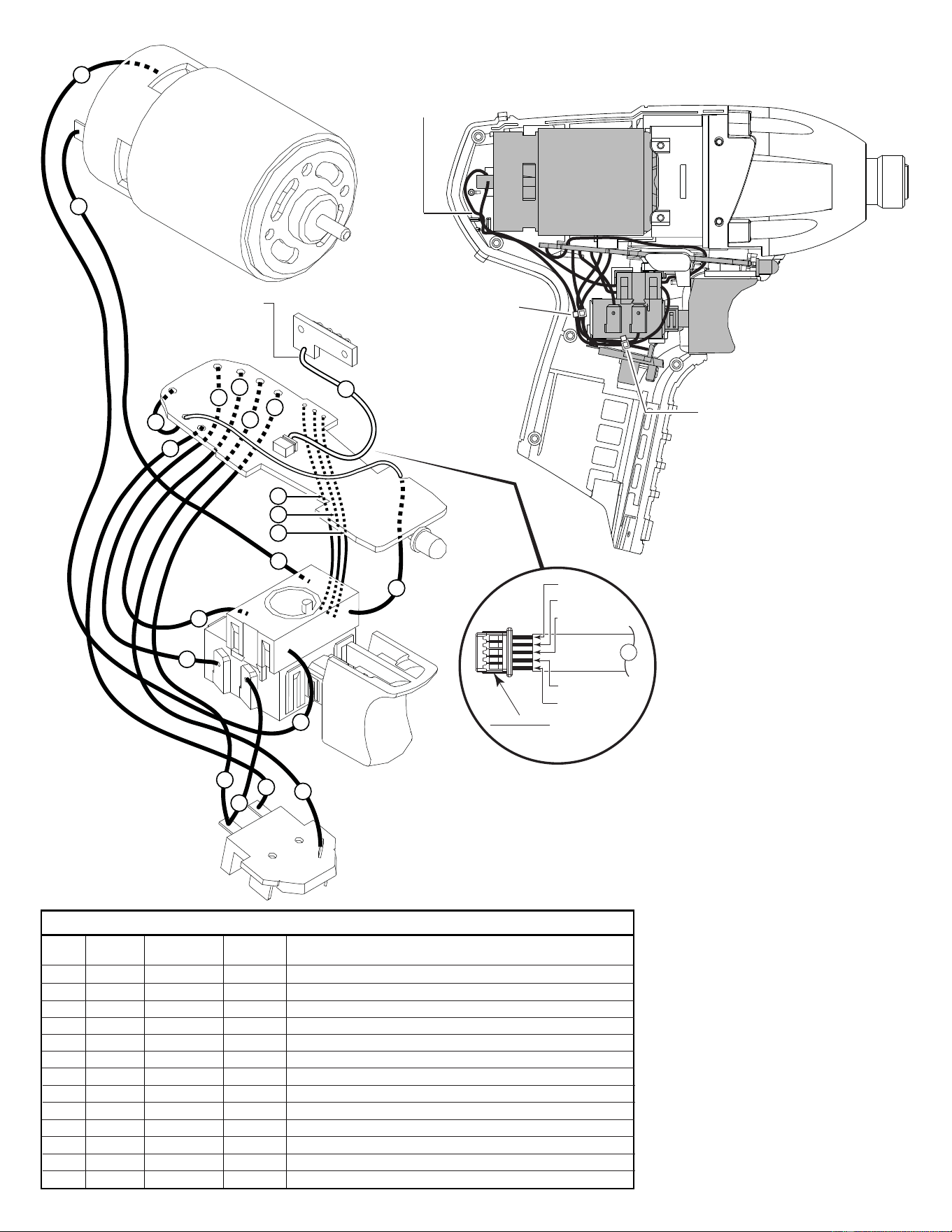
WIRING INSTRUCTION
C08D
EXAMPLE:
Component Parts (Small #)
Are Included When Ordering
The Assembly (Large #).
0
00
SEE REVERSE SIDE
FIG. PART NO. DESCRIPTION OF PART NO. REQ.
30 44-90-1050 Hog Ring (1)
31 45-88-0455 Washer (1)
32 06-65-0085 Pin (2)
35 --------------- Gear Housing (1)
36 14-30-0005 Gearcase Assembly with Bushing (1)
37 06-81-0005 M3.5 x 24 Screw (4)
38 42-06-0310 3/8" Square Drive Anvil Assembly (1)
39 34-40-1885 Rubber Ring (1)
44 --------------- LED Label (1)
45 --------------- Hammer (1)
46 12-20-2452 Service Nameplate (1)
47 --------------- Fuel Gauge LED Assembly (1)
48 42-55-2450 Carrying Case, Optional (1)
49 14-46-1705 Handle Set and Switch Assembly (1)
Service replacement Gear Assembly (28)
comes with a motor mount plate that must
be removed and discarded when servicing.
A Motor Mount Plate (10) already exists on
the Motor Assembly (7).
FIG. LUBRICATION
(Type 'J' Grease, No. 49-08-4220):
36 Coat inside grooves of Bushing inside of gearcase with grease.
38 Lightly coat front washer surface of Anvil (38) with grease.
Place a dab of grease in the Ball holes and in the hole in the
back of the Anvil.
NOTE: Gear Assembly (28) must be attached
to the Motor Assembly (7) prior to installing in
Gearcase Assembly (36).
NOTE:
Pins (13) are shorter
than Pins (32).
= Part number change
from previous service parts list.
54-26-2462
3
3
2
2
1
1
4
4
8
9
8
7
6
5
5
6
7
10
11
12
13
Terminals, Connectors and 1 or 2 End Wire Preparation
Wire
Color
Origin or
Gauge
Wire
No.
Length
WIRING SPECIFICATIONS
1 Black 23-30-0090 ----- Component of the motor assembly.
2 Red 23-30-0090 ----- Component of the motor assembly.
3 White 23-66-1132 ----- Component of the electronics module assembly.
4 Black 23-66-1132 ----- Component of the electronics module assembly.
5 Black 23-66-1132 ----- Component of the electronics module assembly.
6 Red 23-66-1132 ----- Component of the electronics module assembly.
7 White 23-66-1132 ----- Component of the electronics module assembly.
8 Red 23-66-1132 ----- Component of the electronics module assembly.
9 Red 23-66-1132 ----- Component of the electronics module assembly.
10 Yellow 23-66-1132 ----- Component of the electronics module assembly.
11 Blue 23-66-1132 ----- Component of the electronics module assembly.
12 Black 23-66-1132 ----- Component of the electronics module assembly.
13 Sleeve 23-66-1132 ----- Component of the electronics module assy. / Fuel gauge LED.
MOTOR
ASSEMBLY
FUEL GUAGE
LED ASSY.
SLEEVED WIRES
(White, black, red,
green and gray)
ROUTE WIRES 1 AND 2
THROUGH TRAPS IN
THIS AREA.
WIRE
TIE
WIRE
TIE
AS AN AID TO REASSEMBLY, TAKE NOTICE OF WIRE ROUTING AND
POSITION IN WIRE GUIDES AND TRAPS WHILE DISMANTLING TOOL
BE CAREFUL AND AVOID
PINCHING WIRES BETWEEN
HANDLE HALVES WHEN
ASSEMBLING.
WHITE
BLACK
RED
GREEN
GRAY
13
PINNED SIDE OF CONNECTOR
TO FACE DOWN WHEN
INSTALLING TO
PC BOARD
NOTE:
POSITION CONNECTOR PORTION
OF #13 WITH OPEN PINNED SIDE
FACING DOWN TOWARDS THE
PCB (WHITE WIRE SHOULD FACE
FRONT OF TOOL). BE SURE THAT
THE CONNECTOR IS FULLY SEATED.
PCB