1
Installation Guide
AT-USB-EX350-KIT
The Atlona AT-USB-EX350-KIT is a data only USB 3.2 extender kit. It supports simultaneous
extension of 5 Gbps USB 3.2 Gen 1 data and 480 Mbps USB 2.0 data up to 330 feet (100
meters) using a single, cost-eective Category 6A U/FTP cable.
The USB-EX350-KIT is ideal for video conferencing or remote instruction applications where high
data rate USB components including laptops, computers, cameras, microphones, and speakers
are in dierent areas of the room.
The USB-EX350-KIT is comprised of two endpoints. The host endpoint includes a USB-C port
for connection to hosts such as laptops, computers, or other AV equipment that supports USB
connectivity including many Omega
™
Series products. The device endpoint includes three USB-A
ports and one USB-C port for connection to 4K cameras, conferencing bars, microphones,
speakers, and other peripherals. Bidirectional remote power allows the kit to be powered by the
included power supply connected to either the host or device endpoint.
The USB-EX350-KIT is a great solution for routing USB 3.2 Gen 1 data up to 5 Gbps between
components at distances greater than is possible with traditional cabling.
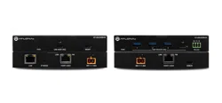
1 x AT-USB-EX350-HS
1 x AT-USB-EX350-DV
1 x 3 ft. USB-A to USB-C cable
1 x 3-pin captive screw connector
4 x Surface mounting brackets
4 x Mounting screws
1 x AC power supply with 2-pin captive screw connector
1 x AC power cord
1 x Insert w/ QR code
Package Contents
USB 3.2 Gen 1 Data Extender Kit
AT-USB-EX350-KIT
IMPORTANT: Visit https://www.atlona.com/product/at-usb-ex350-kit for the
latest rmware updates and User Manual.
2
Installation Guide
AT-USB-EX350-KIT
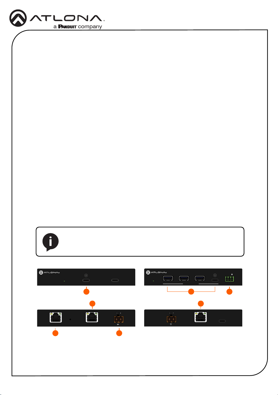
Front
Rear
4
1
5
2
6
3
7
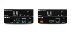
AT-USB-EX350-HS
AT-USB-EX350-HS
PWR USB HOST (5G) MGMT
USB LINKIP MODELAN
LINK FW
48V 1.36A
AT-USB-EX350-HS
PWR USB HOST (5G) MGMT
USB LINKIP MODELAN
LINK FW
48V 1.36A
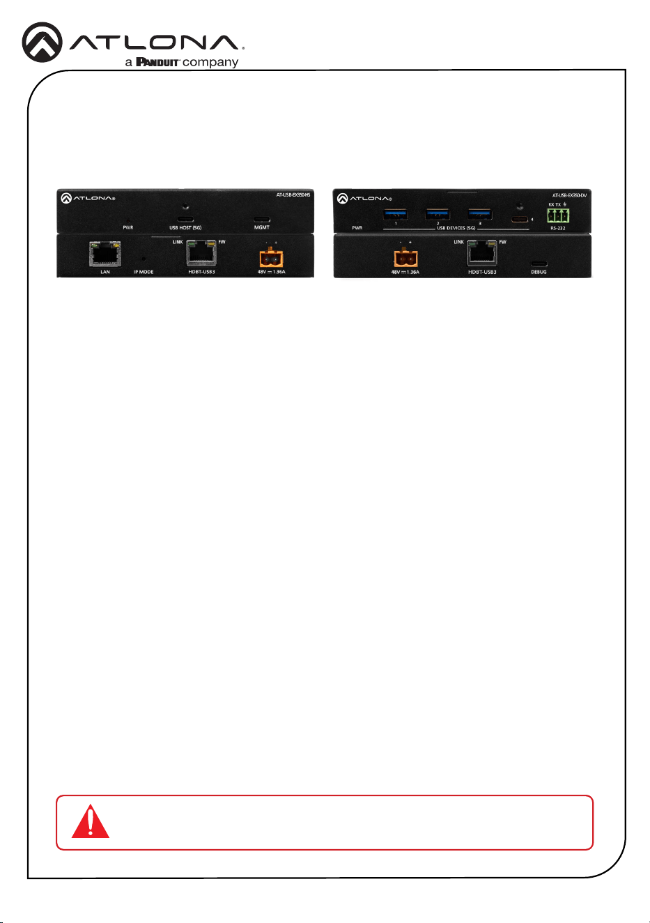
1 PWR
This LED indicator will be green while the
unit is powered and operating normally.
Refer to LED Indicators (page 5) for
more information.
2 USB HOST (5G)
Connect the included USB-C cable from
this port to the host device.
3 MGMT
Connect a USB-C cable from this port to
a computer to perform rmware updates.
Refer to the AT-USB-EX350-KIT User
Manual for more information.
4 LAN
Connect an Ethernet cable from this
port to a network switch on the Local
Area Network (LAN). This connection is
required in order to access the built-in
web server.
• Firmware Update Mode
Press and hold the button for 5
seconds, then release.
• IP Mode
Press and hold the button for 10 to
15 seconds.
• Factory Reset
Press and hold the button for more
than 15 seconds.
5 IP MODE
Use a paperclip or another slim object to
press and hold this recessed button.
The button serves three functions:
6 USB LINK
Connect a category cable (CAT6A U/
FTP), up to 330 feet (100 meters) from
this port to the USB LINK port on the AT-
USB-EX350-DV.
7 48V / 1.36A
Connect the 2-pin captive screw
connector on the included power supply
to this power receptacle.
NOTE: The AT-USB-EX350-KIT supports bidirectional PoE+.
The included power supply can be connected to either the AT-USB-
EX350-HS or AT-USB-EX350-DV.
3
Installation Guide
AT-USB-EX350-KIT
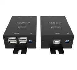
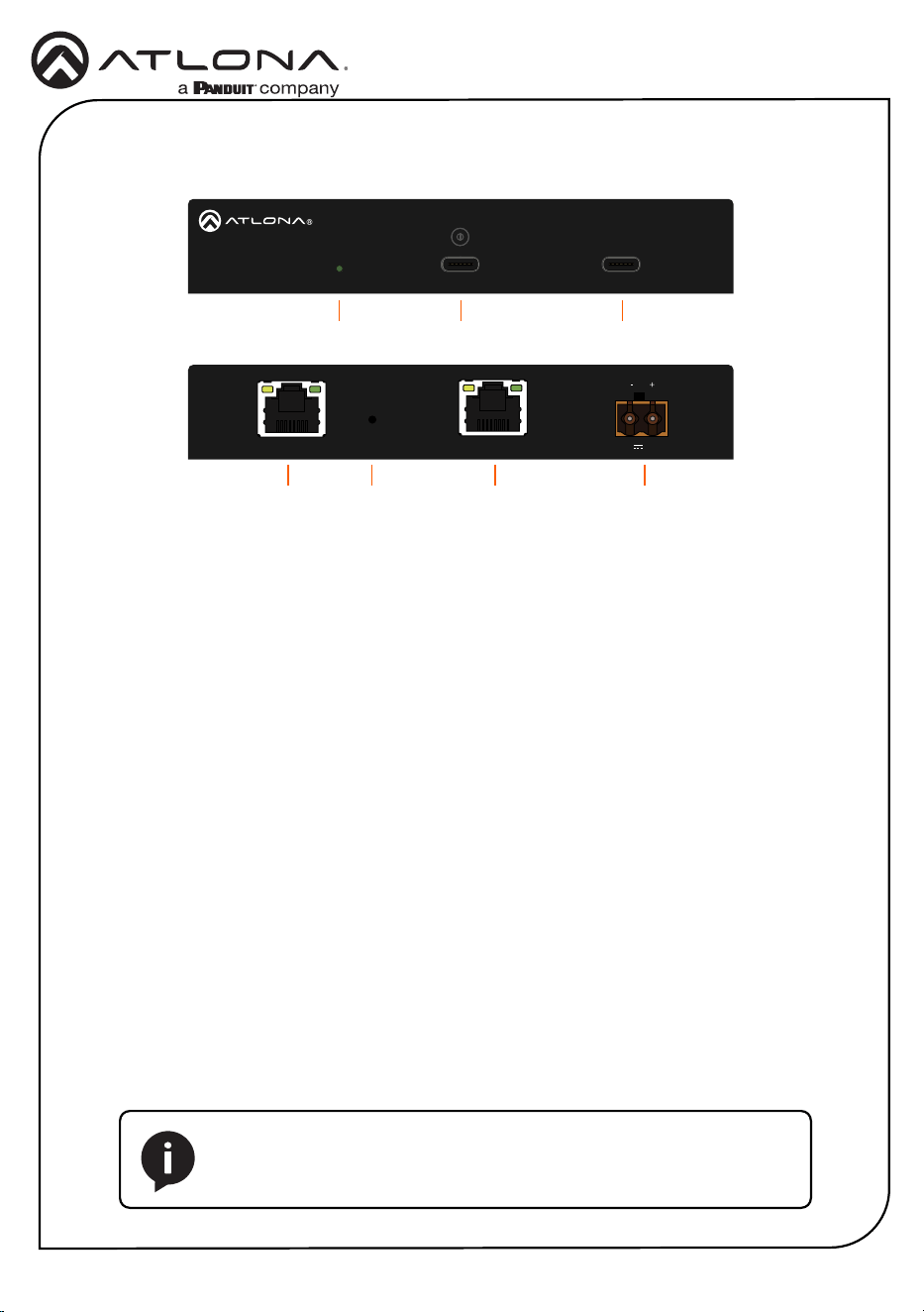
1 DEVICE
This LED indicator will be green while the
unit is powered and operating normally.
Refer to LED Indicators (page 5) for
more information.
2 USB DEVICES (5G)
Connect USB devices to these ports.
These ports support USB 3.2 Gen 1.
3 RS-232
Connect an RS-232 cable from this port to
a control system to enable TCP proxy over
the LAN port.
4 48V / 1.36A
Connect the 2-pin captive screw
connector on the included power supply
to this power receptacle.
5 HDBT-USB3
Connect a category cable (CAT6A U/FTP),
up to 330 feet (100 meters), from this port
to the USB LINK port on the AT-USB-
EX350-HS.
6 DEBUG
Connect a USB-C cable from this port
to a computer for debugging and for
performing Valens rmware updates.
AT-USB-EX350-DV
Front
Rear
4
2
5
31
6
PWR
1 2 3
USB DEVICES (5G)
4
RS-232
AT-USB-EX350-DV
RX TX
DEBUGHDBT-USB3
LINK FW
48V
1.36A
PWR
1 2 3
USB DEVICES (5G)
4
RS-232
AT-USB-EX350-DV
RX TX
DEBUGHDBT-USB3
LINK FW
48V
1.36A
NOTE: The AT-USB-EX350-KIT supports bidirectional PoE+.
The included power supply can be connected to either the AT-USB-
EX350-HS or AT-USB-EX350-DV.
4
Installation Guide
AT-USB-EX350-KIT
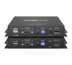
1. Connect a USB cable from the host device to the USB-C HOST port on the AT-USB-EX350-
HS. This port supports USB 3.2 data up to 5 Gbps and USB 2.0 data up to 480 Mbps.
Recommended cable types:
• USB Type-A to Type-C (USB 3.2 Gen 1 or higher)
• USB Type-A to Type-A (USB 3.2 Gen 1 or higher)
Installation
2
AT-USB-EX350-HS
PWR USB HOST (5G) MGMT
USB LINKIP MODELAN
LINK FW
48V 1.36A
AT-USB-EX350-HS
PWR USB HOST (5G) MGMT
USB LINKIP MODELAN
LINK FW
48V 1.36A
PWR
1 2 3
USB DEVICES (5G)
4
RS-232
AT-USB-EX350-DV
RX TX
DEBUGHDBT-USB3
LINK FW
48V
1.36A
PWR
1 2 3
USB DEVICES (5G)
4
RS-232
AT-USB-EX350-DV
RX TX
DEBUGHDBT-USB3
LINK FW
48V
1.36A
NOTE: The AT-USB-EX350-KIT supports bidirectional PoE+.
The included power supply can be connected to either the AT-USB-
EX350-HS or AT-USB-EX350-DV.
2. Connect up to four USB devices to the USB DEVICES (5G) ports on the AT-USB-EX350-DV.
Each port supports USB 3.2 Gen 1 and 5 V / 1.5 A of power.
3. Connect a category cable (CAT6A U/FTP), from the USB LINK port on the AT-USB-EX350-
HS, to the USB LINK port on the AT-USB-EX350-DV. Maximum cable length should not
exceed 330 feet (100 meters) of CAT6A U/FTP. For maximum lengths of other cable types,
refer to the product datasheet.
4. Connect an Ethernet cable from the LAN port to the network. This is necessary to access
the built-in web server, which is used to control and congure the AT-USB-EX350-KIT.
5. OPTIONAL: Connect a 3-pin captive screw connector from the RS-232 port to a third-party
device to enable TCP proxy via LAN control at the host endpoint.
6. Connect the included power supply to either the AT-USB-EX350-HS or AT-USB-EX350-DV
to the 48 V DC / 1.36 A power receptacle.
7. Connect the power supply to an available AC outlet.
3 3
1
4 6
5
5
Installation Guide
AT-USB-EX350-KIT
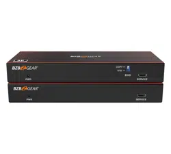
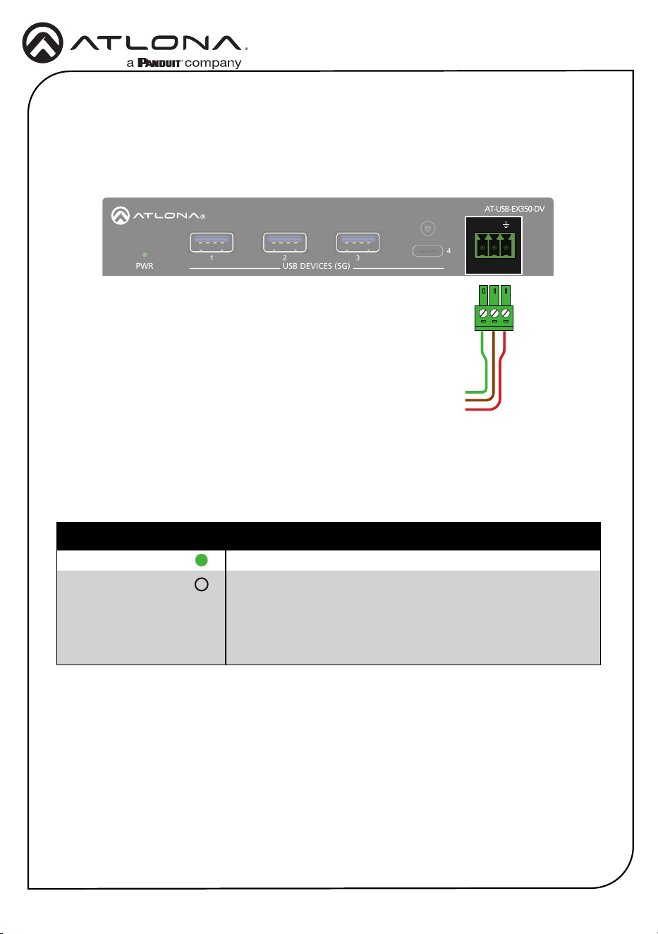
Connect an RS-232 cable from the RS-232 port on the AT-USB-EX350-DV to a device that will
be controlled via a serial connection, such as a camera. This connection will be established over
the network using a TCP Proxy to the AT-USB-EX350-HS. Refer to the AT-USB-EX350-KIT User
Manual for more information.
RS-232
RX
To control system
TX
GND
}
PWR
1 2 3
USB DEVICES (5G)
4
RS-232
AT-USB-EX350-DV
RX TX
DEBUGHDBT-USB3
LINK FW
48V
1.36A
PWR
1 2 3
USB DEVICES (5G)
4
RS-232
AT-USB-EX350-DV
RX TX
DEBUGHDBT-USB3
LINK FW
48V
1.36A
PWR Description
Solid green Unit is powered.
O Unit is not powered.
• Verify that the 2-pin captive screw connector is rmly
secured to the power receptacle.
• Make sure that the power supply is plugged into a live AC
outlet.
The PWR indicator on both the AT-USB-EX350-HS and AT-USB-EX350-DV provide power state
information on both the AT-USB-EX350-HS and AT-USB-EX350-DV.
LED Indicators

6
Installation Guide
AT-USB-EX350-KIT
Accessing the built-in Web Server
The AT-USB-EX350-KIT includes a built-in web server, which allows easy management and
control of all features. Before using the web server, a password must be created.
The AT-USB-EX350-KIT is set to DHCP by default and will receive an IP address from the
network’s DHCP pool if a DHCP server is available. If no DHCP server is detected, the AT-USB-
EX350-KIT will automatically assign itself an APIPA address in the range 169.254.0.1 to
169.254.255.254, with a subnet mask of 255.255.0.0.
1. Make sure that an Ethernet cable is connected between one of the LAN ports on the AT-
USB-EX350-KIT and the network.
2. Launch a web browser and enter the IP address of the unit. By default, the AT-USB-EX350-
KIT is set to DHCP mode and will be assigned an IP address, if a DHCP server is present on
the network.
3. The Login page will be displayed.
4. Enter Atlona in the Password eld.
5. Click Login.
6. The Change Password screen will be displayed.
7. Enter the desired password in the Password eld.
8. Click Apply.
7
Installation Guide
AT-USB-EX350-KIT
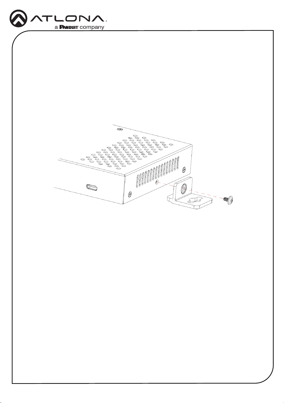
The AT-USB-EX350-KIT includes mounting brackets, which can be used to attach the units to
any at surface. Use the included screws to attach the mounting brackets.
• If using a drywall surface, a #6 drywall screw is recommended.
1. Locate the included screws in the packaging.
2. Align the mounting bracket with the enclosure, matching the holes on the side of the
enclosure with those on the bracket, as shown below.
Mounting Instructions
3. Secure the bracket using a small Phillips screwdriver and a screw.
4. Repeat steps 2 and 3 for the other mounting bracket.
5. Attach the unit to a at surface using the oval-shaped holes on each bracket.
8
Installation Guide
AT-USB-EX350-KIT
25384-R1
© 2025 Atlona Inc. All rights reserved. “Atlona” and the Atlona logo are registered trademarks of Atlona Inc. All other brand names and trademarks or registered
trademarks are the property of their respective owners. Pricing, specications and availability subject to change without notice. Actual products, product images, and
online product images may vary from images shown here.
English Declaration of Conformity
Warranty
Chinese Declaration of Conformity 中国RoHS合格声明
To view the product warranty, use the following link or QR code:
https://atlona.com/warranty/.
由SKU列出於:
https://atlona.com/about-us/china-rohs/.
The English version can be found under the resources tab at:
https://atlona.com/product/at-usb-ex350-kit/.
US International
atlona.com • 408.962.0515 • 41.43.508.4321