1
Installation Guide
AT-OME-EX-KIT-LT
Omega
™
4K/UHD
HDMI Over HDBaseT TX/RX with USB
AT-OME-EX-KIT-LT
The Atlona AT-OME-EX-KIT-LT is an HDBaseT extender for video up to 4K/60 4:2:0, plus
embedded audio, control, and USB over distances up to 130 feet (40 meters) for 4K/UHD, and up
to 230 feet (70 meters) for 1080p/60 video. Part of the Omega™ Series of integration products for
modern AV communications and collaboration, the OME-EX-KIT-LT is HDCP 2.2 compliant and
extends IR and RS-232 control signals. The integrated USB extension addresses the challenge
of connecting between USB devices at remote locations, and is ideal for software video
conferencing and touch or interactive displays. The transmitter includes a USB 2.0 host interface
for a PC, plus two peripheral devices such as a speakerphone, microphone, or keyboard and
mouse. The receiver provides two USB interfaces for devices such as a camera, soundbar, or
display.*
* Both the AT-OME-EX-TX-LT and AT-OME-EX-RX-LT are not compatible with the AT-UHD-
HDVS-300 system for extending USB.
IMPORTANT: Visit http://www.atlona.com/product/AT-OME-EX-KIT-LT for the
latest rmware updates.
1 x AT-OME-EX-TX-LT
1 x AT-OME-EX-RX-LT
2 x Captive screw connectors, 4-pin
1 x Captive screw connector, 2-pin
1 x AT-IR-CS-TX
4 x Mounting plates
8 x Mounting screws
1 x 48 V DC power supply
1 x Installation Guide
Package Contents
2
Installation Guide
AT-OME-EX-KIT-LT
FWHOST
OMEGA
TM
DEVICE
PWR
LINK
HDMI INHDBaseT OUT
RX RXTX
RS-232 IRTEST
FW
OMEGA
TM
DEVICE
PWR
LINK
HDMI OUTHDBaseT IN
RX TXTX
RS-232 IR
AT-OME-EX-RX-LT
DC 48V
DC 48V
-
+
AT-OME-EX-TX-LT
FWHOST
OMEGA
TM
DEVICE
PWR
LINK
HDMI INHDBaseT OUT
RX RXTX
RS-232 IR
TEST
FW
OMEGA
TM
DEVICE
PWR
LINK
HDMI OUTHDBaseT IN
RX TXTX
RS-232 IR
AT-OME-EX-RX-LT
DC 48V
DC 48V
-
+
AT-OME-EX-TX-LT
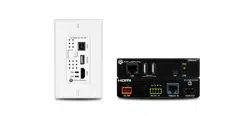
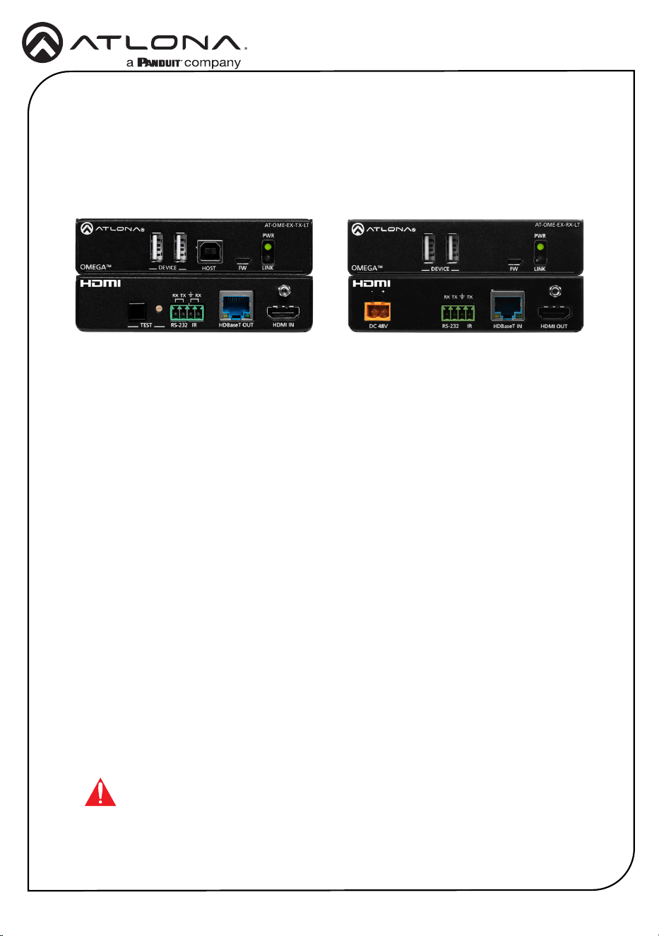
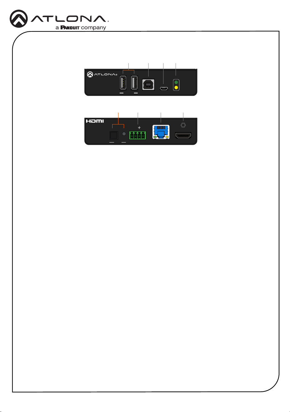
1 DEVICE
Connect up to two USB devices (e.g. mouse, keyboard, etc.) to these ports. These ports
provide 2.5 W per USB device interface.
2 HOST
Connect a USB cable from this port to the host computer.
3 FW
Connect a micro-USB to USB-A cable from this port, to a computer, to update the rmware.
Refer to Updating the Firmware (page 10) for more information.
4 PWR / LINK
The PWR LED indicator will glow green when the AT-OME-EX-TX-LT is powered. The AT-
OME-EX-RX-LT supplies power to the AT-OME-EX-TX-LT over HDBaseT. The LINK LED
indicator glows yellow when a solid link is established between the AT-OME-EX-TX-LT and
AT-OME-EX-RX-LT. Refer to LED Indicators (page 6) for more information.
5 TEST
Press and release this button to test the integrity of the HDBaseT connection, between
the transmitter and the receiver. If the connection is good, then the TEST LED indicator
will glow bright green. Refer to Testing the HDBaseT Connection (page 7) for more
information.
6 RS-232 / IR
Connect the included 4-pin captive screw block to this receptacle. Refer to RS-232 and IR
(page 4) for more information.
7 HDBaseT OUT
Connect a category cable from this port to the HDBaseT IN port of the AT-OME-EX-RX-LT
or other PoE-compatible receiver.
8 HDMI IN
Connect an HDMI cable from this port to the source device.
Front
Rear
8
65 7
1
2 3 4
AT-OME-EX-TX-LT
3
Installation Guide
AT-OME-EX-KIT-LT
FWHOST
OMEGA
TM
DEVICE
PWR
LINK
HDMI INHDBaseT OUT
RX RXTX
RS-232 IRTEST
FW
OMEGA
TM
DEVICE
PWR
LINK
HDMI OUTHDBaseT IN
RX TXTX
RS-232 IR
AT-OME-EX-RX-LT
DC 48V
DC 48V
-
+
AT-OME-EX-TX-LT
FWHOST
OMEGA
TM
DEVICE
PWR
LINK
HDMI INHDBaseT OUT
RX RXTX
RS-232 IRTEST
FW
OMEGA
TM
DEVICE
PWR
LINK
HDMI OUT
HDBaseT IN
RX TXTX
RS-232 IR
AT-OME-EX-RX-LT
DC 48V
DC 48V
-
+
AT-OME-EX-TX-LT
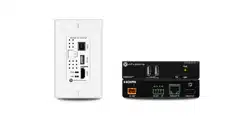
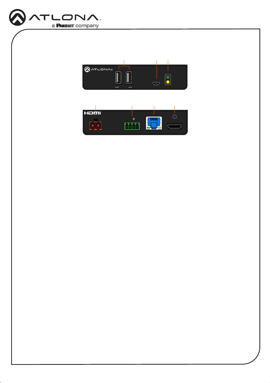
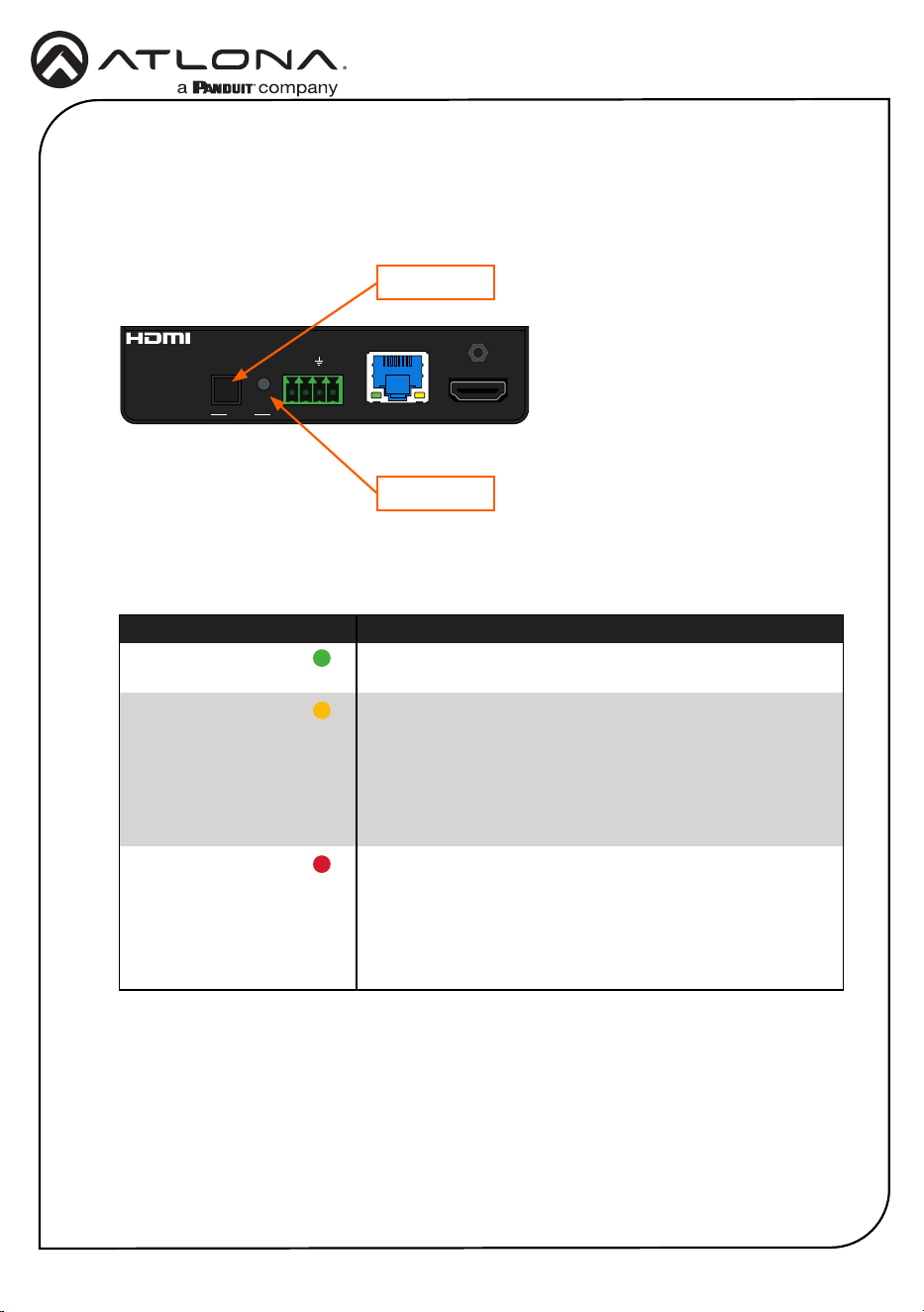
1 DEVICE
Connect up to two USB 2.0 devices (e.g. mouse, keyboard, etc.) to these ports.
These ports provide 2.5 W per USB device.
2 FW
Connect a micro-USB to USB-A cable from this port, to a computer, to update the rmware.
Refer to Updating the Firmware (page 10) for more information.
3 PWR / LINK
The PWR LED indicator will glow green when the AT-OME-EX-RX-LT is powered. The LINK
LED indicator glows yellow when a solid link is established between the AT-OME-EX-TX-LT
and AT-OME-EX-RX-LT. Refer to LED Indicators (page 6) for more information.
4 DC 48V
Connect the included 2-pin captive screw block from this receptacle to the power supply.
This connection supplies power to the AT-OME-EX-TX-LT. Refer to Power (page 4) for
more information.
5 RS-232 / IR
Connect the included 4-pin captive screw block to this receptacle. Refer to RS-232 and IR
(page 4) for more information.
6 HDBaseT IN
Connect a category cable from this port to the HDBaseT OUT port of the AT-OME-EX-TX-
LT. The AT-OME-EX-TX-LT is powered by the AT-OME-EX-RX-LT over HDBaseT.
7 HDMI OUT
Connect an HDMI cable from this port to the display (sink) device.
AT-OME-EX-RX-LT
Front
Rear
7
54 6
1
2 3
4
Installation Guide
AT-OME-EX-KIT-LT
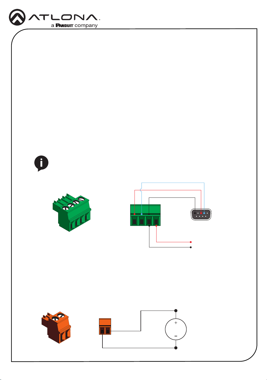
The AT-OME-EX-KIT-LT provides pass-through transport of RS-232 protocol and/or IR over
HDBaseT, which allows communication between a control system and an RS-232 or IR device.
This step is optional.
1. Use wire strippers to remove a portion of the cable jacket.
2. Remove at least 3/16” (5 mm) from the insulation of the RX, TX, and GND wires for the RS-
232 connection.
3. Insert the TX, RX, and GND wires into correct terminal using one of the included 4-pin
captive screw connectors.
4. Repeat step 2 for the S and GND wires for the IR connection.
5. Insert the S (signal) wire in to the TX terminal and the ground wire to the GND terminal.
6. Tighten the captive screws to secure the wires in place. Do not over-tighten or use high-
torque devices to prevent damage to the connector block.
NOTE: Typical DB9 connectors use pin 2 for TX, pin 3 for RX, and pin 5 for
ground. On some devices functions of pins 2 and 3 are reversed. Note that the
signal (S) pin for the IR is labeled as “TX” on the port.
GND
to control system
or AT-VCC-IR-KIT
DE-9 (RS-232) port
RX
TX
S
GND
RS-232 and IR
Power
1. Locate the included orange captive-screw block, and loosen the screws to allow room to
insert the copper wiring.
2. Wire the included power supply to the block, as shown below. Do not use high-torque
devices, when securing the wires to the captive-screw terminal block, as this may damage
the screws and/or block.
Black
White
48 V DC
power supply
5
Installation Guide
AT-OME-EX-KIT-LT
1. Connect a UHD/HD source to the HDMI IN port on the AT-OME-EX-TX-LT.
2. Connect a UHD/HD display to the HDMI OUT port on the AT-OME-EX-RX-LT.
3. Connect a USB cable from the host computer to the HOST port on the AT-OME-EX-TX-LT.
4. Connect up to two USB devices (speakerphone, etc.) to the DEVICE ports on the AT-OME-
EX-TX-LT. These ports provide 2.5 W per USB device interface.
5. Connect up to two USB devices (mouse, keyboard, etc.) to the DEVICE ports on the AT-
OME-EX-RX-LT. These ports provide 2.5 W per USB device interface.
6. Connect a category cable, from the HDBaseT OUT port on the AT-OME-EX-TX-LT, to the
HDBaseT IN port on the AT-OME-EX-RX-LT.
7. OPTIONAL: Connect an RS-232 cable between a control system and the RS-232 port on
the AT-OME-EX-TX-LT. Connect the RS-232 device to the RS-232 port on the AT-OME-EX-
RX-LT. Refer to RS-232 and IR (page 4) for more information.
8. OPTIONAL: OPTIONAL: Connect the included IR emitter to the IR port on the AT-OME-EX-
RX-LT. Refer to RS-232 and IR (page 4) for more information.
9. Connect the included 48 V DC power supply to the DC 48V power receptacle on the AT-
OME-EX-RX-LT.
10. Connect the power supply to an available AC outlet.
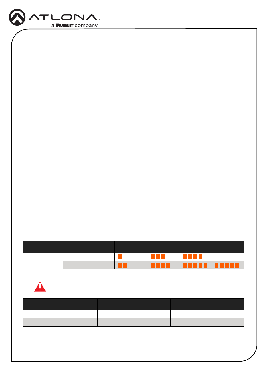
Refer to the tables below for recommended cabling when using Altona products with HDBaseT.
The green bars indicate the signal quality when using each type of cable. Higher-quality signals
are represented by more bars.
Core Shielding CAT5e CAT6 CAT6a CAT7
Solid UTP (unshielded) N/A
STP (shielded)
*Atlona recommends TIA/EIA 568-B termination for optimal performance.
Cable* Max. Distance @ 4K Max. Distance @ 1080p
CAT5e / CAT6 115 feet (35 meters) 200 feet (60 meters)
CAT6a / CAT7 130 feet (40 meters) 230 feet (70 meters)
IMPORTANT: Stranded or patch cables are not recommended due to
performance issues.
Installation
Cable Recommendation Guidelines
6
Installation Guide
AT-OME-EX-KIT-LT
The PWR and LINK LED indicators on both the AT-OME-EX-TX-LT and AT-OME-EX-RX-LT
provide basic information on the current status of the AT-OME-EX-KIT. The information in the
table below applies to both units. Refer to Testing the HDBaseT Connection (page 7) for
more information on the TEST LED indicator.
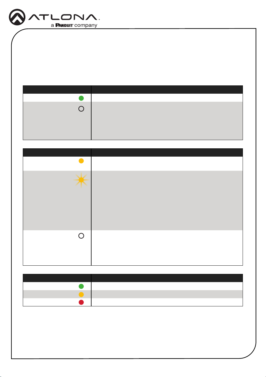
TEST Description
Solid green Bit Error Rate (BER) and all cable pairs are good.
Solid yellow BER test has passed, but one or more cable pairs are not good.
Solid red Both BER and one or more cable pair tests have failed.
PWR Description
Solid green Unit is powered.
O Unit is not powered.
• Verify that the locking connector is securely fastened to the
power receptacle.
• Make sure that the power supply is connected to an active
AC outlet.
LINK Description
Solid yellow The link integrity between the AT-OME-EX-TX-LT and the AT-
OME-EX-RX-LT is good.
Flashing yellow Poor signal integrity between the AT-OME-EX-TX-LT and the
AT-OME-EX-RX-LT.
• Make sure that the category cable between the HDBaseT
IN port on the AT-OME-EX-TX-LT and the HDBaseT OUT
port on the AT-OME-EX-RX-LT is secure.
• The category cable may be compromised. Try using a
dierent category cable. Make sure that the cable is solid
core. Stranded or patch cables are not recommended.
O The link integrity between the AT-OME-EX-TX-LT and the AT-
OME-EX-RX-LT is compromised.
• Check the category cable between the HDBaseT IN port
on the AT-OME-EX-TX-LT and the HDBaseT OUT port on
the AT-OME-EX-RX-LT.
LED Indicators
7
Installation Guide
AT-OME-EX-KIT-LT
Testing the HDBaseT Connection
1. Make sure the AT-OME-EX-KIT-LT is powered. It is unnecessary to disconnect the source
and display from the system.
2. Press and release the TEST button on the front panel of the AT-OME-EX-TX-LT.
FWHOST
OMEGA
TM
DEVICE
PWR
LINK
HDMI INHDBaseT OUT
RX RXTX
RS-232 IR
TEST
FW
OMEGA
TM
DEVICE
PWR
LINK
HDMI OUTHDBaseT IN
RX TXTX
RS-232 IR
AT-OME-EX-RX-LT
DC 48V
DC 48V
-
+
AT-OME-EX-TX-LT
TEST button
TEST LED
3. During the test procedure, the TEST LED indicator will begin ashing. Once the test has
completed, the LED will return one of the following states:
TEST LED Description
Solid green Both the Bit Error Rate (BER) and cable quality tests have
passed.
Solid yellow The BER test has passed, but one or more of the cable
pairs has failed during the test.
• Make sure that the HDBaseT cable is securely
connected between the HDBaseT OUT and HDBaseT
IN ports.
• Try replacing the HDBaseT cable and re-test.
Solid red Both BER and one or more cable pair tests have failed.
• Make sure that the HDBaseT cable is securely
connected between the HDBaseT OUT and HDBaseT
IN ports.
• Try replacing the HDBaseT cable and re-test.
8
Installation Guide
AT-OME-EX-KIT-LT
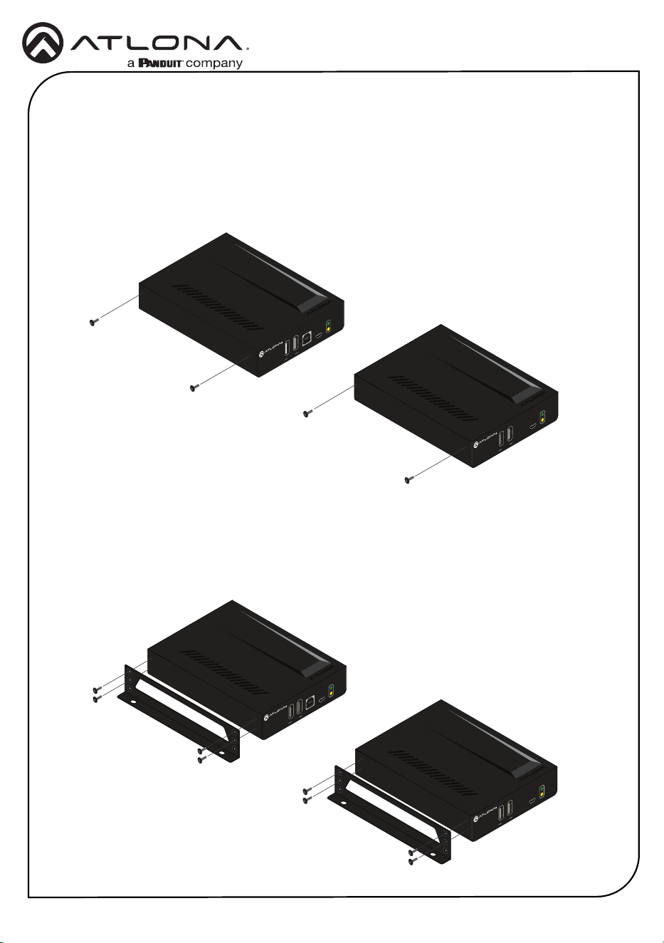
Both the AT-OME-EX-TX-LT and AT-OME-EX-RX-LT include mounting brackets, which can be
used to attach the unit to any at surface. Use the included screws to attach the mounting
brackets.
1. Using a small Phillips screwdriver, remove the two screws from the side of the enclosure.
FW
OMEGA
TM
DEVICE
PWR
LINK
2. Position one of the mounting brackets, as shown below, aligning the holes on the side of the
enclosure with one set of holes on the mounting bracket.
3. Use the screws from Step 1 to attach the mounting bracket, plus two additional screws
(included) to complete the installation. Four screws should be used to secure each
mounting bracket, as shown below.
Mounting Instructions
FWHOST
OMEGA
TM
DEVICE
PWR
LINK
FW
OMEGA
TM
DEVICE
PWR
LINK
FWHOST
OMEGA
TM
DEVICE
PWR
LINK
9
Installation Guide
AT-OME-EX-KIT-LT
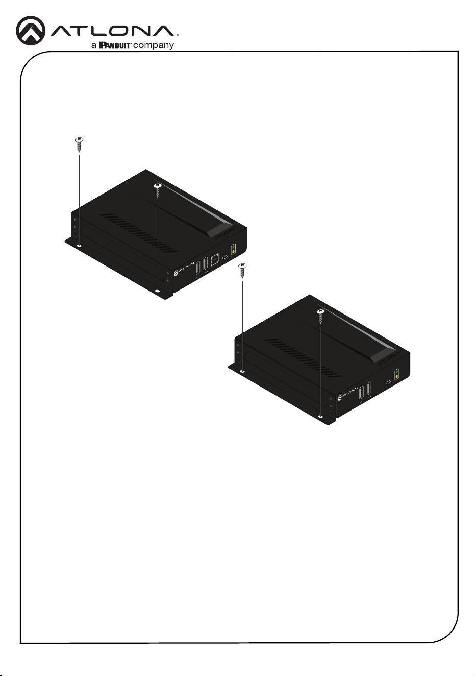
4. Repeat Steps 1 through 3 to attach the second mounting bracket to the opposite side of the
unit.
5. Mount the unit to a at surface using the oval-shaped holes, on each mounting bracket.
If using a drywall surface, a #6 drywall screw is recommended.
FW
OMEGA
TM
DEVICE
PWR
LINK
FWHOST
OMEGA
TM
DEVICE
PWR
LINK
10
Installation Guide
AT-OME-EX-KIT-LT
Updating the Firmware
Requirements:
• AT-OME-EX-TX-LT
• AT-OME-EX-RX-LT
• Firmware le
• Computer running Windows
• USB-A to micro-USB cable
• USB Firmware Update Tool
1. Disconnect power from the AT-OME-EX-RX-LT.
2. Make sure the AT-OME-EX-TX-LT and AT-OME-EX-RX-LT are connected to the HDBaseT
ports using a category (CAT-5e or better) cable.
3. Connect a USB-A to micro-USB cable between the PC and the FW port on the AT-OME-EX-
TX-LT (transmitter).
4. Power the AT-OME-EX-RX-LT.
5. If a USB UPDATE folder is opened automatically, notate the drive letter and close the folder.
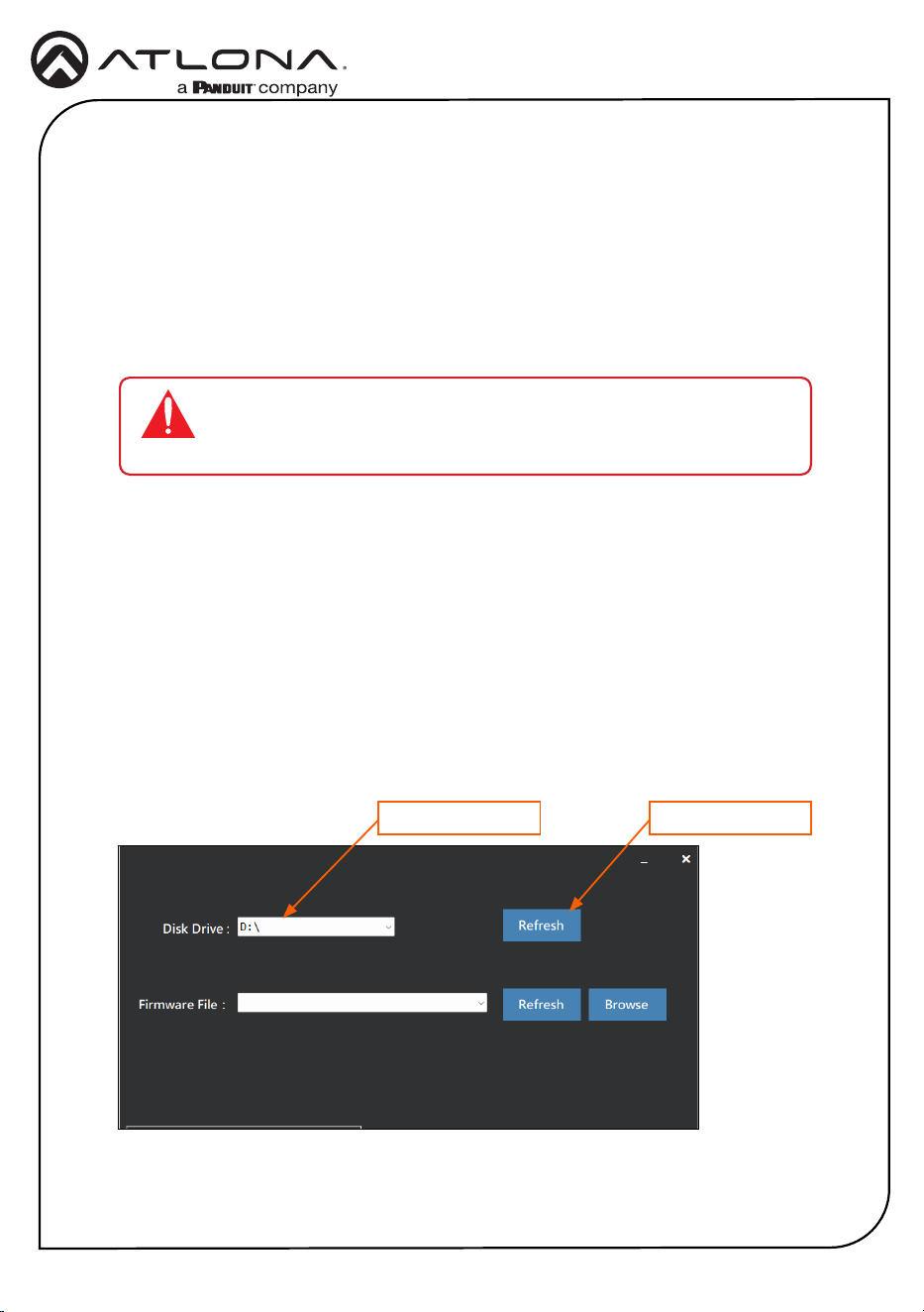
6. Launch the USB Update Tool.
7. The drive letter of the mounted drive for the unit will be displayed in the Disk Drive eld.
If it is not, click the Refresh button.
Mounted drive letter Refresh button
IMPORTANT: The AT-OME-EX-KIT-LT should be updated as a kit, and
the TX and RX should be connected via their HDBaseT connectors prior
to the rmware update.
8. Click the Browse button and select the rmware le. Once the rmware le is selected, it
will appear in the Firmware File eld. If the rmware le is not displayed in this eld, click
the Refresh button.
11
Installation Guide
AT-OME-EX-KIT-LT
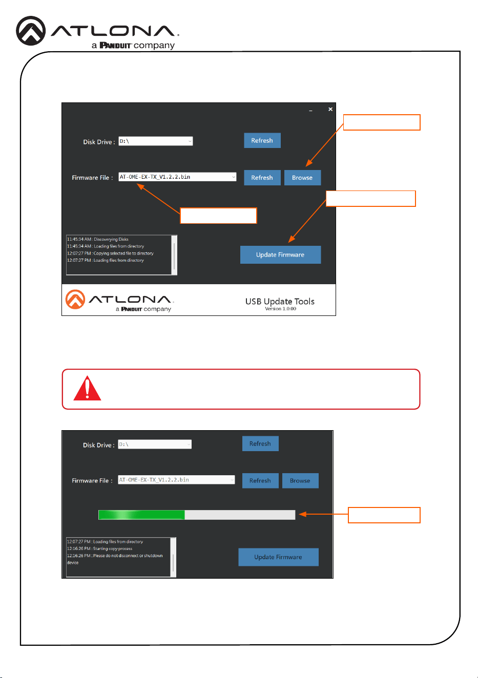
9. Click the Update Firmware button.
Firmware file
Browse button
Update Firmware button
10. The rmware update process will begin and will be monitored by a progress bar.
IMPORTANT: Do not disconnect power from the unit while performing
the rmware update procedure.
Progress bar
12
Installation Guide
AT-OME-EX-KIT-LT
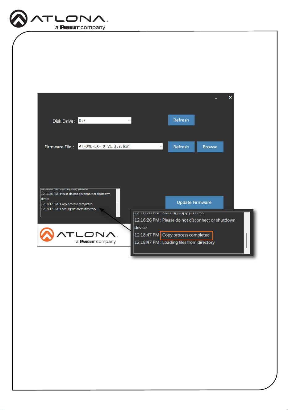
11. After the update process has completed, the Copy process completed message will be
displayed in the message window.
The PWR LED indicator, on the front panel, will ash green while the unit is being updated.
Do not disconnect the USB cable during the update process. When the PWR LED stops
ashing and is solid green, the update process will be complete.

13
Installation Guide
AT-OME-EX-KIT-LT
Notes

14
Installation Guide
AT-OME-EX-KIT-LT
Notes

15
Installation Guide
AT-OME-EX-KIT-LT
Notes
16
Installation Guide
AT-OME-EX-KIT-LT
25129-R5
English Declaration of Conformity
The English version can be found under the resources tab at:
https://atlona.com/product/at-ome-ex-kit-lt/.
Warranty
Chinese Declaration of Conformity 中国RoHS合格声明
To view the product warranty, use the following link or QR code:
https://atlona.com/warranty/.
由SKU列出於:
https://atlona.com/about-us/china-rohs/.
© 2024 Atlona Inc. All rights reserved. “Atlona” and the Atlona logo are registered trademarks of Atlona Inc. All other brand names and trademarks or registered
trademarks are the property of their respective owners. Pricing, specications and availability subject to change without notice. Actual products, product images, and
online product images may vary from images shown here.
US International
atlona.com • 408.962.0515 • 41.43.508.4321
®
The terms HDMI, HDMI High-Denition Multimedia Interface, HDMI trade dress and the HDMI Logos are
trademarks or registered trademarks of HDMI Licensing Administrator, Inc.