ROCKER SWITCH AND SOLENOID INSTALLATION
INSTRUCTIONS FOR ATV WINCHES
Every effort has been made to ensure the accuracy and
completeness of the information in this manual. We reserve
the right to change, alter and/or improve the product and this
document at any time without prior notice.
NOTICE
If you have questions regarding your Champion Power Equipment
product, we can help. Please call customer service at
1-877-338-0999.
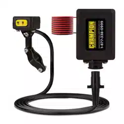
Solenoid Mounting
1. Before mounting the solenoid bracket be aware of the cable
lengths. The rocker switch cable is 8.4’, the battery leads
coming from the solenoid are 2’ and the leads that go to the
winch from the solenoid are 5.9’.
2. Locate a secure place on your ATV to place the mounting
bracket. Select a location on your vehicle that will remain out
of the way and away from any interference that may occur
while vehicle is in use.
3. Drill 4 holes in desired area for mounting with an 11/32 drill
bit.
4. Once the mounting plate has been secured, attach the plate
to the solenoid box by sliding the solenoid box on to the plate
and locking it in to place.
Winch Wiring
1. After mounting the solenoid in a secure spot run the 4’ power
lead with quick connect to the winch. We recommend running
the leads along the frame and securing with wire ties.
NOTICE
If there is any excess cable, bind with a wire tie to prevent cable
damage.
2. Place the switch on the solenoid box in the Off position before
connecting the battery leads to the battery.
3. When connecting the rocker switch cable, run the rocker
switch cable along the frame, securing with wire ties,
allowing 6 to 8 inches of free play for handle bar movement.
Congratulations on your purchase of a Champion Power Equipment
Solenoid and Rocker Switch. CPE designs and builds our products
to strict specifications. With proper use and maintenance, it will
bring years of satisfying service.
Compatible only with Champion winch models 12003 (2000 lb.),
13005 (3000 lb.), 13004 (3000 lb.), 13502 (3000 lb.),
13050 (3000 lb.).
NOTICE
All Terrain Vehicles vary in design: Solenoid and switch
placement will vary based on your specific model.
Assembly Instructions
1. Attach switch base plate (#8) to the bottom of the rocker
switch using bolts (#6) and washers (#7).
2. Using bolt (#10) attach extension plate to plate (#8) with bolt
(#10) and one washer, lock washer and nut (#3, 4, 5).
3. Place one handle bar plate (#1) on each side of the extension
plate and place one bolt (#2) through all three plates with a
washer and lock washer. Place nut on bolt (Do not tighten
nut).
4. Position handle bar plates around handle bar were mounting
is preferred and plate bolt (#2) through the plates along with
washers and nut (#3, 4, 5).
5. Tighten nuts from steps 3 and 4.
5836-M-OP REV 20250603
EN
Champion Power Equipment, Inc.
1
7
6
9
5
8
10
2 3 4
