INSTALLATION MANUAL
MODEL #201461
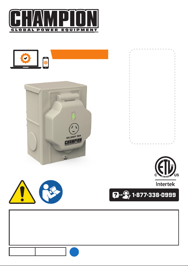
50 AMP POWER INLET BOX
Champion Power Equipment, Inc.
or visit championpowerequipment.com
SAVE THESE INSTRUCTIONS. This manual contains important safety precautions which
should be read and understood before operating the product. Failure to do so could result in
serious injury. This manual should remain with the product.
Specifications, descriptions and illustrations in this manual are as accurate as known at the
time of publication, but are subject to change without notice.
5484-M-OP REV 20241122
EN
ACTIVATE YOUR WARRANTY
by registering your product:
cha mpionpowerequipment.com
SERIAL NO.

201461 - 50 AMP POWER INLET BOX TABLE Of CONTENTS
2
TABLE Of CONTENTS
Introduction ................................................................ 3
Safety Definitions........................................................... 4
Important Safety Instructions .............................................. 5
Instructions for Champion Power Inlet Box ......................................5
Before Installation ...........................................................5
Safety Labels ................................................................6
Safety Symbols ..............................................................6
Controls and features ...................................................... 7
Power Inlet Box (PIB) .........................................................7
Parts Included ...............................................................8
Tools Needed ................................................................8
Generator and Accessories Needed ............................................8
Equipment Description...................................................... 9
Installation ................................................................. 9
Unpacking ..................................................................9
Power Inlet Box (PIB) .........................................................9
Installing Power Inlet Box (PIB) .............................................. 10
Specifications ............................................................. 13
Warranty* ................................................................. 14
FOR PARTS BREAKDOWN
Search by model number at
championpowerequipment.com

201461 - 50 AMP POWER INLET BOX INTRODUCTION
3
INTRODUCTION
Congratulations on your purchase of a Champion Power Equipment (CPE) product. CPE designs,
builds, and supports all of our products to strict specifications and guidelines. With proper product
knowledge, safe use, and regular maintenance, this product should bring years of satisfying
service.
Every effort has been made to ensure the accuracy and completeness of the information in this
manual at the time of publication, and we reserve the right to change, alter and/or improve the
product and this document at any time without prior notice.
CPE highly values how our products are designed, manufactured, operated, and serviced as well
as providing safety to the operator. Therefore, it is IMPORTANT to review this product manual
and other product materials thoroughly and be fully aware and knowledgeable of the assembly,
operation, dangers and maintenance of the product before use. Fully familiarize yourself, and
make sure others who plan on operating the product fully familiarize themselves too, with the
proper safety and operation procedures before each use. Please always exercise common sense
and always err on the side of caution when operating the product to ensure no accident, property
damage, or injury occurs. We want you to continue to use and be satisfied with your CPE product for
years to come.
When contacting CPE about parts and/or service, you will need to supply the complete model and
serial numbers of your product. Transcribe the information found on your product’s nameplate label
to the table below
CPE TECHNICAL SUPPORT TEAM
1-877-338-0999
MODEL NUMBER
201461
SERIAL NUMBER
DATE OF PURCHASE
PURCHASE LOCATION

201461 - 50 AMP POWER INLET BOX SAfETy DEfINITIONS
4
SAfETy DEfINITIONS
The purpose of safety symbols is to attract your attention to possible dangers. The safety symbols,
and their explanations, deserve your careful attention and understanding. The safety warnings do
not by themselves eliminate any danger. The instructions or warnings they give are not substitutes
for proper accident prevention measures.
DANGER
DANGER indicates a hazardous situation which, if not avoided, will result in death or serious
injury.
WARNING
WARNING indicates a hazardous situation which, if not avoided, could result in death or
serious injury.
CAUTION
CAUTION indicates a hazardous situation which, if not avoided, could result in minor or
moderate injury.
NOTICE
NOTICE indicates information considered important, but not hazard-related (e.g., messages
relating to property damage).

201461 - 50 AMP POWER INLET BOX IMPORTANT SAfETy INSTRUCTIONS
5
IMPORTANT SAfETy INSTRUCTIONS
WARNING
Cancer and Reproductive Harm - www.P65Warnings.ca.gov
Instructions for Champion Power Inlet Box
This manual has been prepared for familiarizing dealer/installer with the design, application, and
installation of the equipment.
Read the manual carefully and comply with all instructions. It is recommended that a licensed
electrician or an individual with complete knowledge of electricity perform the installation of the
power inlet box.
This manual or a copy of this manual should remain with the power inlet box. Every effort has been
taken to make sure that the contents of this manual are accurate and current.
The manufacturer reserves the right to change, alter or otherwise improve this manual and the
product at any time without prior notice and without any obligation or liability whatsoever.
The manufacturer cannot anticipate every possible circumstance that might involve a hazard.
The warnings in this manual, tags and decals affixed to the unit are, therefore, not all-inclusive.
If using a procedure, work method or operating technique the manufacturer does not specifically
recommend, be sure to always follow all local municipal, state and national electrical codes to
ensure safety for personnel.
Many accidents are caused by failing to follow simple and fundamental rules, codes and
precautions. Before installing, or operating this equipment, read the SAFETY RULES carefully.
All installations must comply with local municipal, state and national codes.
Before Installation
CAUTION
Consult with your Local municipal, State and National electrical codes for proper mandatory
wiring methods.
201461 - 50 AMP POWER INLET BOX IMPORTANT SAfETy INSTRUCTIONS
6
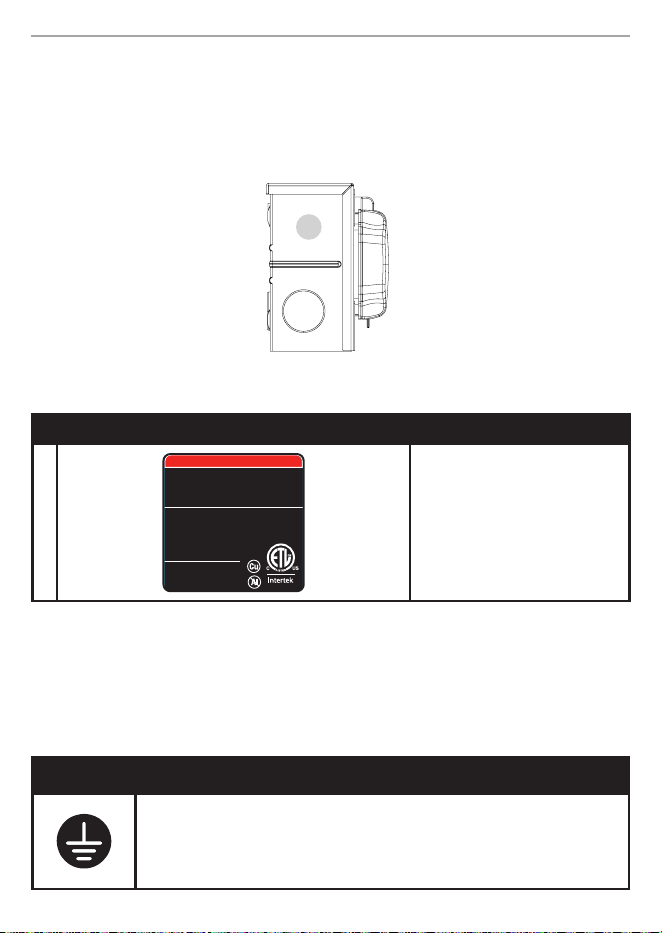
Safety Labels
These labels warn you of potential hazards that can cause serious injury. Read them carefully.
If a label comes off or becomes hard to read, contact Technical Support Team for possible
replacement.
Side
A
LABEL DESCRIPTION
A
PELIGRO DANGER
4000058
ELECTRIC SHOCK HAZARD
For power inlet only. Not for use as an outlet. Connect
the cord to this inlet and the generator prior to starting
the generator. Terminals may be energized when the
cord is connected. Shut down the generator before
disconnecting the cord from this inlet and the generator.
RIESGO DE DESCARGA ELÉCTRICA
Sólo par a entrada de corriente. No debe utilizarse como
enchufe. Conec te el cable a esta toma y al generador
antes de arrancar el generador. Las terminales pueden
estar energizadas cuando el cable está conectado.
Apague el generador antes de
desconectar el cable de esta
entrada y del generador.
Conforms to / Conforme a
UL STD.498
Certified to / C onforme a
CSA STD.C22.2 #42
5246-L-SF-B
K --- --- --- ---
ColorsAPN 5246-L-SF
Rev B
Size ~6 0 x 60 m m
Artwork Notes
3mm corner radius; 2mm safe margin;
to be printed
on
White
substrate.
Revision Changes
Rev B: 20 241031 - Changed Fr ench text to sp anish
under “conforms to...”
This art work belongs to Cham pion Power Equipment. T he contents are con fidential and privil eged and shall not be discl osed to or used by or for
outside pa rties withou t the explicit consen t of Champion Power E quipment.
Electric Shock Hazard
Safety Symbols
Some of the following symbols may be used on this product. Please study them and learn their
meaning. Proper interpretation of these symbols will allow you to more safely operate the product.
SYMBOL MEANING
Ground. Consult with local electrician to determine grounding requirements
before operation.
201461 - 50 AMP POWER INLET BOX CONTROLS AND fEATURES
7
CONTROLS AND fEATURES
Read this installation manual before operating your power inlet box. Familiarize yourself with the
location and function of the controls and features. Save this manual for future reference.
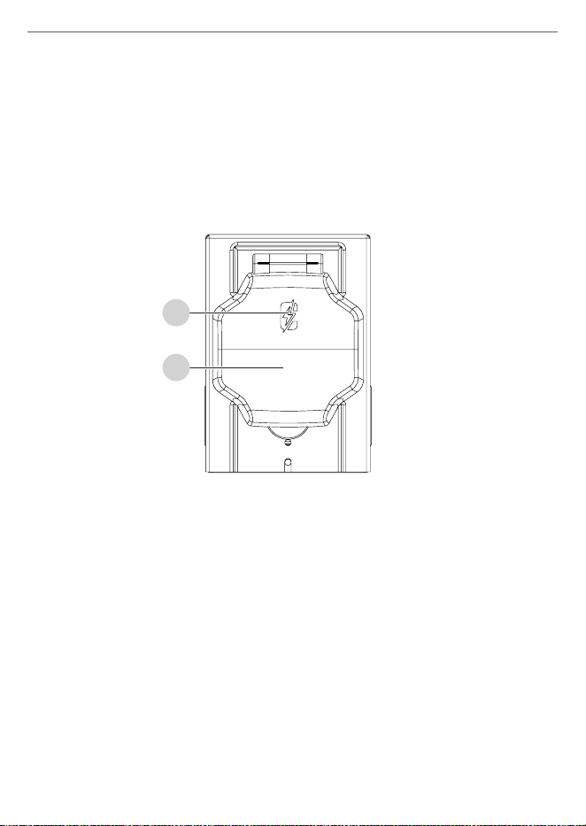
Power Inlet Box (PIB)
1
2
1. Power LED
2. Outlet Cover

201461 - 50 AMP POWER INLET BOX CONTROLS AND fEATURES
8
Parts Included
Knockout Cover ..............................................................1
Knockout Nut ................................................................1
Knockout Gasket .............................................................1
Tools Needed
– Power drill
– #2 Philips screwdriver
– Level
– Fastening Hardware
Generator and Accessories Needed
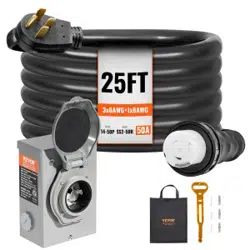
– Champion 25 ft. (7.6 m) Power Cord [#100828] or equivalent 50A 125/250V generator power
cord with SS2-50 connectors
– 120/240V Generator with 14-50R Outlet
– Manual Transfer Switch, Generator Interlock Kit, or Off-Grid Electrical Panel

201461 - 50 AMP POWER INLET BOX EqUIPMENT DESCRIPTION
9
EqUIPMENT DESCRIPTION
The easy to install Power Inlet Box (PIB), when paired with a manual transfer switch, interlock kit,
or off-grid electrical panel, allows convenient power in your house during a power outage with
your generator located safely outside - ONLY use generators OUTSIDE and far away from doors,
windows and vents. With this Power Inlet Box, there is no longer a need to run extension cords from
the generator through doors and windows to power your appliances during utility power outages.
You will now have easily accessible power at your termination point of choice.
INSTALLATION
Unpacking
1. Use care when unpacking to avoid damaging components.
2. Layout all parts and compare to Parts Included section.
Power Inlet Box (PIB)
NOTICE
Since a portable generator is always operated outdoors, far away from occupied buildings, the
included NEMA 3R outdoor rated Power Inlet Box (PIB) will be used to connect the generator to
the termination point.
When the generator is providing power to the PIB with the Power Cord, the green LED indicator
will be lit showing power to the PIB receptacle.

201461 - 50 AMP POWER INLET BOX INSTALLATION
10
Installing Power Inlet Box (PIB)
NOTICE
Locate the PIB on an exterior wall that will ensure the generator will be far away from
windows, doors, and vents.
Installation may vary depending on your homes wall material and construction.
During PIB installation, extra measures may be needed to ensure proper weatherproofing at
the PIB hole cavity.
Read and follow the manufacturer’s instructions for the manual transfer switch, interlock kit,
or off-grid electrical you plan to use as your termination point.
Always use a sheathed cord assembly, cable, or wiring with the proper standardized colored
sheathing and AWG size (minimum AWG 6) and four (4) copper wire conductors.
Consult a professional if you are unsure of proper method for your home.
CAUTION
Consult with your Local municipal, State and National electrical codes for proper mandatory
wiring methods.
1. Run the appropriate AWG sized wires (minimum AWG 6 copper) into the power inlet box.
CAUTION
PVC cement can eat through wire insulation. Apply in thin layer, ensuring no PVC cement drips
down into the conduit or contacts the wire insulation.
2. If using conduit, apply a small, thin layer of PVC cement to the conduit, position the conduit
fitting over the conduit and press together firmly.
3. Place a level on the side of the power inlet box and ensure the box is level. Using the 3 holes
provided on the back of the box, mount PIB on exterior wall using the appropriate fasteners
and water sealing method.

201461 - 50 AMP POWER INLET BOX INSTALLATION
11
NOTICE
Determine appropriate hardware, based off your homes wall material and construction such as
mounting blocks, sealant, concrete screws, etc.
4. Loosen screw on the grounding terminal inside the box. Cut green grounding wire of cable to
final length and strip wire insulation. Making sure both green grounding wires from the PIB
receptacle and cable are inserted in-between plates on the grounding terminal of PIB.
5. Cut red, black, and white wires of cable to final length and strip wire insulation.
6. On the back of the outlet, insert white wire into hole marked “W”, tighten corresponding
screw. Insert red wire into hole marked“X”, tighten corresponding screw. Insert black wire
into hole marked “Y”, tighten corresponding screw.
White
Black
Red
Green
NOTICE
Tighten all screws to 35 inch-pounds torque.

201461 - 50 AMP POWER INLET BOX INSTALLATION
12
7. Carefully fold wires into box, replace cover, and tighten bottom screw. Consult
manufacturer’s instructions for the transfer switch or your off-grid or interlocked electrical
panel to make the proper wire connections at your termination point.
DANGER
Generator exhaust contains carbon monoxide, a colorless, odorless, poisonous gas. Breathing
carbon monoxide will cause nausea, dizziness, fainting or death. If you start to feel dizzy or
weak, get to fresh air immediately.

201461 - 50 AMP POWER INLET BOX SPECIfICATIONS
13
SPECIfICATIONS
Model ............................................................... 201461
Outlet ...............................................................SS2-50P
Enclosure Rating ..................................................... NEMA 3R
Conduit Knockout Size ...............................3/4 inch (19.05 mm) nominal
Listings ..............................................UL 498, CSA C22.2 NO. 42

201461 - 50 AMP POWER INLET BOX WARRANTy*
14
WARRANTy*
CHAMPION POWER EQUIPMENT
1 YEAR LIMITED WARRANTY
Warranty qualifications
To register your product for warranty and FREE lifetime call center technical support please visit:
https://www.championpowerequipment.com/register
To complete registration you will need to include a copy of the purchase receipt as proof of original
purchase. Proof of purchase is required for warranty service. Please register within ten (10) days
from date of purchase.
Repair/Replacement Warranty
CPE warrants to the original purchaser that the mechanical and electrical components will be
free of defects in material and workmanship for a period of one year (parts and labor) from
the original date of purchase and 90 days (parts and labor) for commercial and industrial use.
Transportation charges on product submitted for repair or replacement under this warranty are the
sole responsibility of the purchaser. This warranty only applies to the original purchaser and is not
transferable.
Do Not Return The Unit To The Place Of Purchase
Contact CPE’s Technical Service and CPE will troubleshoot any issue via phone or e-mail. If the
problem is not corrected by this method, CPE will, at its option, authorize evaluation, repair or
replacement of the defective part or component at a CPE Service Center. CPE will provide you with
a case number for warranty service. Please keep it for future reference. Repairs or replacements
without prior authorization, or at an unauthorized repair facility, will not be covered by this warranty.
Warranty Exclusions
This warranty does not cover the following repairs and equipment:
Normal Wear
Products with mechanical and electrical components need periodic parts and service to perform
well. This warranty does not cover repair when normal use has exhausted the life of a part or the
equipment as a whole.
Installation, Use and Maintenance
This warranty will not apply to parts and/or labor if the product is deemed to have been misused,
neglected, involved in an accident, abused, loaded beyond the product’s limits, modified, installed
improperly or connected incorrectly to any electrical component. Normal maintenance is not
covered by this warranty and is not required to be performed at a facility or by a person authorized
by CPE.

201461 - 50 AMP POWER INLET BOX WARRANTy*
15
Other Exclusions
This warranty excludes:
– Cosmetic defects such as paint, decals, etc.
– Wear items such as filter elements, o-rings, etc.
– Accessory parts such as starting batteries, and storage covers.
– Failures due to acts of God and other force majeure events beyond the manufacturer’s control.
– Problems caused by parts that are not original Champion Power Equipment parts.
Limits of Implied Warranty and Consequential Damage
Champion Power Equipment disclaims any obligation to cover any loss of time, use of this
product, freight, or any incidental or consequential claim by anyone from using this product.
THIS WARRANTY IS IN LIEU OF ALL OTHER WARRANTIES, EXPRESS OR IMPLIED, INCLUDING
WARRANTIES OF MERCHANTABILITY OR FITNESS FOR A PARTICULAR PURPOSE.
A unit provided as an exchange will be subject to the warranty of the original unit. The length of the
warranty governing the exchanged unit will remain calculated by reference to the purchase date of
the original unit.
This warranty gives you certain legal rights which may change from state to state or province to
province. Your state or province may also have other rights you may be entitled to that are not listed
within this warranty.
Contact Information
Address
Champion Power Equipment, Inc.
6370 S Pioneer Way, Unit 101
Las Vegas, NV 89113 USA
www.championpowerequipment.com
Customer Service
Toll Free: 1-877-338-0999
info@championpowerequipment.com
Fax no.: 1-562-236-9429
Technical Service
Toll Free: 1-877-338-0999
tech@championpowerequipment.com
24/7 Tech Support: 1-562-204-1188