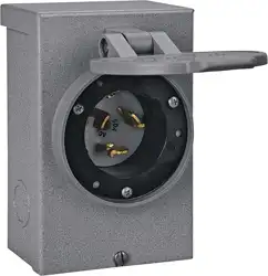
POWER INLET BOX
CAT. NO. PB50
50 Amps., 120/240 VAC
INSTALLATION INSTRUCTIONS
IMPORTANT: Installation of this power inlet box and related wiring must be done by a qualified electrician in
compliance with all applicable electrical codes.
When used to power a structure, this inlet must be used in conjunction
with a transfer switch. Not for indoor use. When using an engine driven generator, locate away from doors and
windows to avoid the build-up of carbon monoxide from the engine exhaust in enclosed areas.
INSTALLING A REMOTELY LOCATED POWER INLET BOX FOR SUPPLYING POWER TO THE
POWER INLET OF A TRANSFER SWITCH OR PANEL
Installing the Power Inlet Box
Mount the power inlet box on the outside of the building in a convenient location, using the three holes provided in
the back of the cabinet. Using copper wire only and approved wiring methods, run the wiring through one of the
knockouts in the cabinet to a junction box located near the transfer switch. If using conduit, pull at least three color-
coded wires (AWG #8 minimum, AWG #4 maximum) -- use white for neutral, and two other distinguishing colors
(typically black and red) for the 240V line. If not using conduit or if otherwise required, include a green wire as a
separate ground wire.
Strip the wire insulation 5/8" (do not tin conductors) and connect the wires in the power inlet box as follows making
sure there is no wire insulation in any terminal and the inlet terminal screws are tightened to 35 inch-pounds torque
using a 5/32 Allen wrench :
240 Volt line wires to the brass terminals marked "X" and "Y".
White wire to the nickel-plated neutral terminal marked “W”
Green power inlet wire to green ground screw terminal on inside of cabinet.
If required, green wire to green ground screw terminal on inside of cabinet.
Installing a junction box and cord connector
The cord assembly from the junction box to the transfer switch power inlet is to be made of four-conductor cord
suitable for a 50 Amp. load. The insulation on each of the wires is colored to identify with the standardized coding in
plugs and receptacles. Wire colors are usually white, green, black, and red. One end of the cord will be connected to
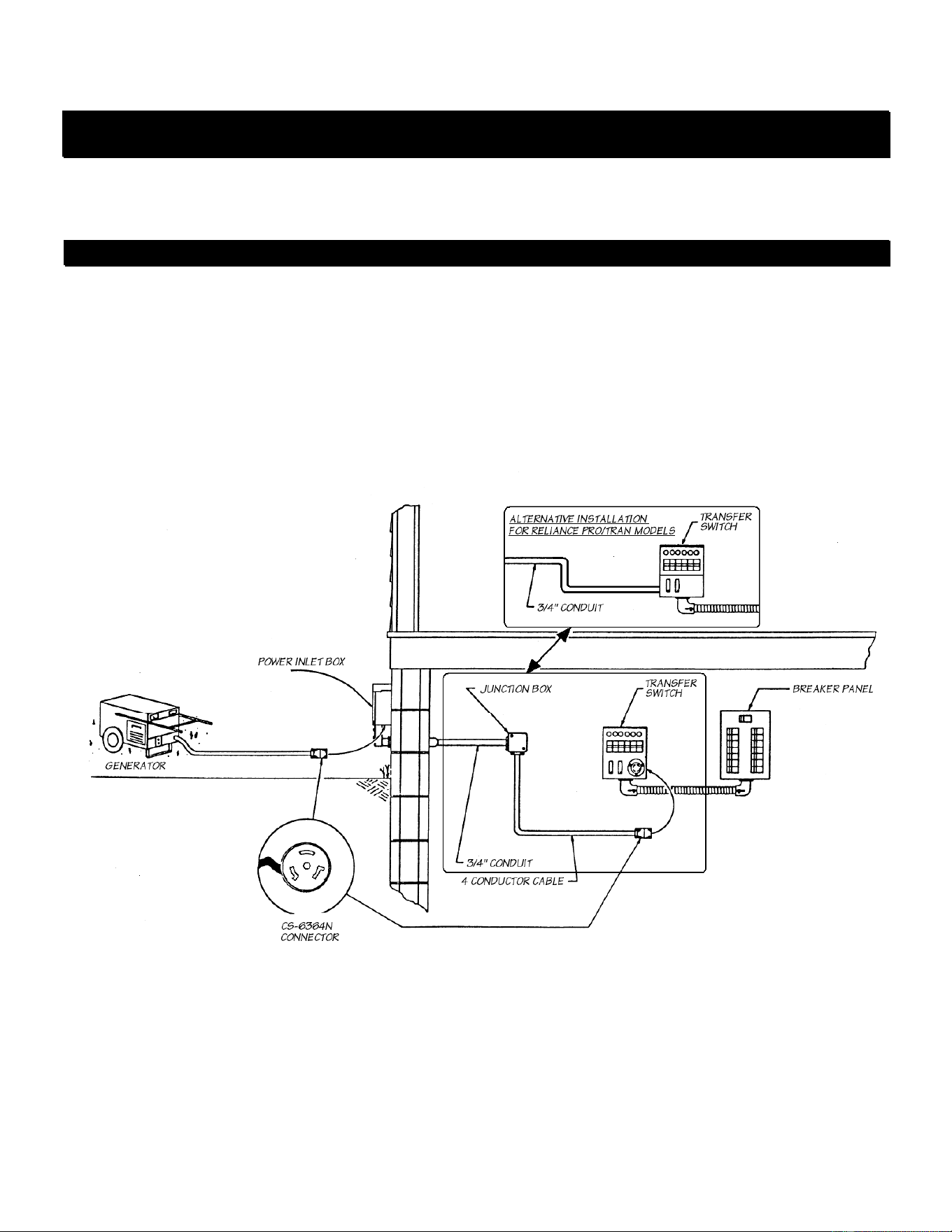
the wires in the junction box, and the opposite end will be connected to a Type CS-6364N (such as the Reliance Cat.
No. LL550C) connector which will mate with the power inlet on the face of the transfer switch. Remove one junction
box knockout and insert a cord grip and the cord.
Connect the wires in the junction box as follows:
Red and black cord wires to 240V line wires from the power inlet box.
White cord wire to the white neutral wire from the power inlet box.
Green cord wire to junction box ground screw.
Green wire from power inlet box, if required, to junction box ground screw.
Following the wiring device manufacturer's instructions, wire the CS-6364N connector as follows:
Red and black wires to the brass terminals marked "X" and "Y".
White wire to the nickel-plated neutral terminal marked "W".
Green wire to the green ground terminal marked "G".
A diagram of the above arrangement is shown below. It is not necessary to detach the connector from the swtich or
panel when generator is not in use, and for convenience may be left in place at all times.
INSTALLING A REMOTELY LOCATED POWER INLET BOX FOR CONNECTION DIRECTLY TO A
HARD-WIRE TRANSFER SWITCH OR PANEL:
Installation will generally be as described above, except that the wiring can be run directly to the transfer switch or
panel. Wire connections are to be made at the transfer switch or panel according to manufacturer's instructions.
PREPARING A CORD FROM THE GENERATOR TO THE POWER INLET BOX:
Using a 4-conductor 50 Amp. portable cord suitable for the purpose, attach a male plug matching the configuration of
the generator outlet to one end, and a Type CS-6364N connector (which will mate with the power inlet in the power
inlet box) to the opposite end.
Following the wiring device manufacturer's instructions, wire the generator plug and the CS-6364N connector as
follows:
Red and black wires to the brass terminals marked "X" and "Y".
White wire to the nickel-plated neutral terminal marked "W".
Green wire to the green ground terminal marked "G".
RELIANCE CONTROLS CORPORATION / 2001 YOUNG COURT / RACINE, WI 53404 / (262) 634-6155
9-8-14