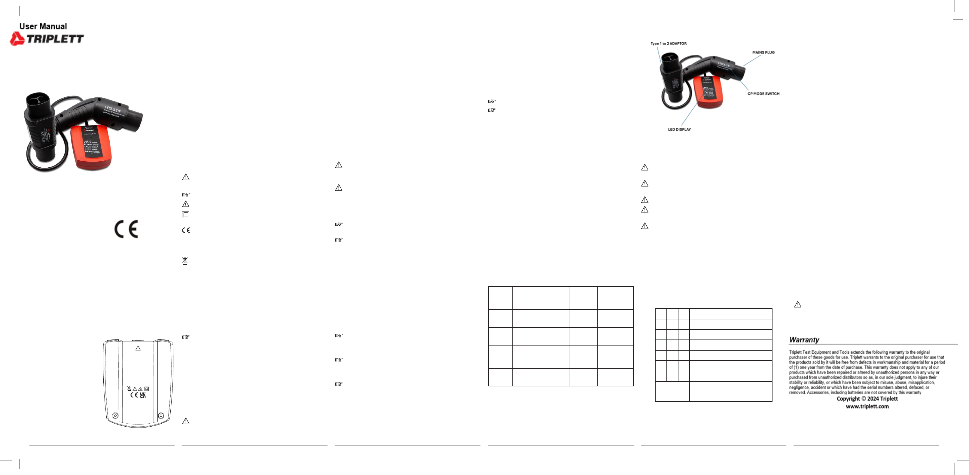
4.5 Operation elements
5.0 Error messages during the installation and function test
The unit may only be used in properly earthed electrical
installations!
Before use, chewck that the unit is in working order, for example
on a known voltage source.
T
h
e t
e
s
t
e
r d
o
e
s n
o
t d
e
t
e
c
t r
e
v
e
r
s
e
d N<
-
>
P
E c
o
n
n
e
c
t
i
o
n
s
.
In case of crosstalk from very long energized to non-ener-
gized wires wrong indications are possible.
I
f
t
h
e
C
P
-
M
o
d
e
-
s
w
i
t
c
h
i
s
i
n
p
o
s
i
t
i
o
n
“
C
”
b
u
t
a
l
l
i
n
d
i
c
a
t
o
r
s
a
r
e
OFF there could be
•
no voltage at all,
•
misfunction of the charger,
•
wrong wiring at the chargers input or output.
T
h
i
s n
e
e
d
s f
u
r
t
h
e
r i
nv
e
s
t
i
g
a
t
i
o
n o
f t
h
e r
o
o
t c
a
u
s
e
.
5
.
1 S
o
c
ke
t i
n
s
p
e
c
t
i
o
n
T
o
t
e
s
t
s
o
c
k
e
t
s
a
n
d
c
o
n
n
e
c
t
i
n
g
c
a
b
l
e
s
,
i
n
s
e
r
t
t
h
e
d
e
v
i
c
e
i
nt
o
t
h
e
s
o
c
k
e
t
.
A statement about the test result is made by means of the display legend
below.
○
●
●
OK
● ●
○
L
/
N
s
w
a
p
ped
●
○
●
L/PE swapped
○
●
○
PE missing
○ ○
●
N missing
○ ○ ○
L missing
● ● ●
L/PE swapped & PE missing
○
= LED OFF
●
= LED ON
4.0. Intended use
The appliance may only be used under the conditions and for the
p
u
r
p
o
s
e
s
f
o
r
w
h
i
c
h
i
t
w
a
s
d
e
s
i
g
n
e
d.
I
n
t
h
i
s
r
e
g
a
r
d,
p
a
r
t
i
c
u
l
a
r
a
t
t
e
nt
i
o
n
m
u
s
t
b
e
p
a
i
d
t
o
t
h
e
s
a
f
e
t
y
i
n
s
t
r
u
c
t
i
o
n
s
,
t
h
e
t
e
c
h
n
i
c
a
l
s
p
e
c
i
c
a
t
i
o
n
s
w
i
t
h
regard to the ambient conditions and the use of the appliance in dry
environments.
4
.
1 U
s
i
n
g H
D
T E
V
S
E W
a
l
l
b
o
x W
i
r
i
n
g T
e
s
t
e
r 8
4
1
9
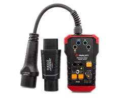
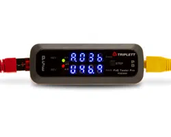
The EVSE Wallbox Wiring Tester indicates the status of the charger
o
u
t
p
u
t
s
o
c
k
e
t
(
v
e
h
i
c
l
e
s
i
d
e
)
a
n
d
n
o
t
t
h
e
f
u
n
c
t
i
o
n
a
l
i
t
y
o
f
t
h
e
c
h
a
r
g
e
r
i
t
s
e
l
f
.
It shows if the vehicle charging is possible.
T
h
e
c
h
a
r
g
e
r
i
t
s
e
l
f
c
o
u
l
d
p
r
e
v
e
nt
c
h
a
r
g
i
n
g
i
n
c
a
s
e
o
f
w
r
o
n
g
w
i
r
i
n
g
at the chargers input.
•
S
e
l
e
c
t C
P M
o
d
e “
A
” w
i
t
h t
h
e s
l
i
d
e
r s
w
i
t
c
h
.
•
C
o
n
n
e
c
t
H
D
T
E
V
S
E
W
a
l
l
b
o
x
W
i
r
i
n
g
T
e
s
t
e
r
t
o
t
h
e
T
y
p
e
-
2
c
o
n
n
e
c
t
o
r
of the charging point.
•
S
e
l
e
c
t
C
P
M
o
d
e
“
B
”
w
i
t
h
t
h
e
s
l
i
d
e
r
s
w
i
t
c
h
,
t
h
e
c
h
a
r
g
i
n
g
p
o
i
nt
s
h
o
u
l
d
show “ready to charge”.
•
Select CP Mode “C” with the slider switch, the charging point should
start charging.
•
T
h
e
t
e
s
t
r
e
s
u
l
t
a
b
o
u
t
t
h
e
w
i
r
i
n
g
o
f
t
h
e
T
y
p
e
2
s
o
c
k
e
t
a
n
d
i
n
f
o
r
m
a
t
i
o
n
t
o
the present voltages is shown on the table on the instrument.
•
After you completed all your measurements select CP Mode “A” with
the slider switch to stop charging.
• Unplug HDT EVSE Wallbox Wiring Tester from the charging point.
4.2 Proximity Pilot (PP) State (Cable Simulation)
The HDT EVSE Wallbox Wiring Tester is congured internally (680 Ohm
between PP and PE) to simulate 20 A current capability.
4.3 Control Pilot (CP) State (Vehicle Simulation)
With the CP Mode slider switch various vehicle states can be simulat-
ed. Vehicle states are simulated with different resistances connected
between CP and PE conductors. Correlation between resistance and
vehicle states is shown in Table below.
Vehicle
St
a
t
e
State Description CP-PE-
R
es
is
-
tance
CP terminal
v
o
l
ta
ge
A Electric vehicle not
connected
open (∞) ±12 V
@
1 KHz
B Vehicle connected, not
ready to charge
2.74 K +9 V /-12 V @
1 KHz
C
E
l
ec
t
r
ic
v
e
h
ic
l
e
c
o
n
n
ec
-
ted, ready to charge,
v
e
n
t
i
l
a
t
i
on
no
t
r
e
q
u
i
r
e
d
8
8
2 Ω
+
6 V
/ -
1
2 V
@
1 KHz
[E] CP Error „E“
(see below)
0 Ω 0 V
4.4 CP Error “E”-simulation
“E” - CP Error simulation could be realized by pushing the slider switch
into (spring loaded) position [E]. This will simulate behavior of the station
when there is a short circuit between CP and PE through internal diode
(acc. to standard IEC/EN 61851-1).
In the case of CP Error (“E” is pushed), result should be aborting of the
charging process and new charging process is prevented.
Scope of delivery:
1 HDT EVSE Wallbox Wiring Tester
1 Instruction Manual
2.
0 T
r
a
n
s
p
o
r
t a
n
d s
t
o
r
a
g
e
P
l
e
a
s
e
k
e
e
p
t
h
e
o
r
i
g
i
n
a
l
p
a
c
k
a
g
i
n
g
f
o
r
l
a
t
e
r
s
h
i
p
m
e
nt
,
e
.
g
.
f
o
r
c
a
l
i
b
r
a
-
tion. Transport damage due to inadequate packaging is excluded from
t
h
e w
a
r
r
a
nt
y
.
The unit must be stored in a dry place in a closed room.
If the unit has been transported or stored at extreme temperatures,
it requires at least 2 hours of acclimatization to room temperature
b
e
fo
re
b
e
i
ng
s
w
i
tch
e
d
o
n.
3.0 Safety instructions
The HDT EVSE Wallbox Wiring Tester has been built and tested in
accordance with the current safety regulations for electrical measuring,
control and laboratory equipment as per IEC/EN 61010-1 and has left
the factory in safe and perfect condition.
The HDT EVSE Wallbox Wiring Tester is only a testing device.
The HDT EVSE Wallbox Wiring Tester does not test for absence
of voltage.
To avoid electric shocks, the applicable safety and VDE regula-
tions must be observed when working with voltages above 120 V
(60 V) DC or 50 V (25
V) RMS AC. The values in brackets apply to
restricted voltage ranges (for example in the medical or agricultur-
a
l
se
c
t
or
)
.
Before use, make sure that the device is functioning properly. The
tester may only be used within the specied measuring ranges.
If the safety of the user is no longer guaranteed, the unit must be
t
a
k
e
n o
u
t o
f s
e
r
v
i
c
e a
n
d p
r
o
t
e
c
t
e
d f
r
o
m f
u
r
t
h
e
r u
s
e
.
Safety is no longer guaranteed if the unit:
•
has obvious damage
•
no longer performs the desired measurements
•
ha
s
b
e
en
s
t
o
r
e
d
f
o
r
t
oo
lon
g
u
n
d
e
r
u
n
f
a
v
o
r
a
b
l
e
c
on
d
i
t
ions
•
has been subjected to mechanical stress during transport
•
ha
s
b
e
en
c
on
t
a
m
i
na
t
e
d
b
y
l
e
a
k
i
n
g
ba
t
t
e
r
i
e
s
•
h
a
s
b
e
e
n
a
l
t
e
r
e
d
i
n
a
ny
w
a
y
a
n
d
n
o
l
o
n
g
e
r
c
o
r
r
e
s
p
o
n
d
s
t
o
i
t
s
original condition
In the above cases, the unit must no longer be used!
The unit may only be opened by trained personnel. Before open-
ing, make sure that the unit has been disconnected from all meas-
u
r
in
g
c
ir
c
u
it
s
.
The accident prevention regulations laid down by the professional
associations for electrical systems and equipment must be strictly
observed during all tasks.
To ensure correct operation and long life, do not leave the instru-
ment in direct sunlight where it may heat up.
Content
1
.
0
I
n
t
r
o
d
u
c
t
i
o
n / S
c
o
p
e o
f d
e
l
i
v
e
r
y
2.0
Transport an storage
3.0 Safety instructions
4.0 Intended use
4.1 Using HDT EVSE Wallbox Wiring Tester 8419
4.2 Proximity Pilot (PP) State (Cable Simulation)
4.3 Control Pilot (CP) State (Vehicle Simulation)
4.4 CP Error “E”-simulation
4
.
5 O
p
e
r
at
i
o
n e
l
e
m
e
nt
s
5.0 Error messages during the installation and function test
5.1 Socket inspection
6.0 Care and maintenance
7.0 Technical data
References marked on tester or in instruction manual:
W
a
r
n
i
n
g
o
f
p
o
s
s
i
b
l
e
d
a
n
g
e
r
s
;
o
b
s
e
r
v
e
t
h
e
a
s
s
o
c
i
a
t
e
d
n
o
t
e
i
n
t
h
e
operating instructions.
Note, information.
W
a
r
n
i
n
g o
f e
l
e
c
t
r
i
c
a
l vo
l
t
a
g
e - r
i
s
k o
f e
l
e
c
t
r
i
c s
h
o
c
k
.
Double or reinforced insulation throughout according to class II
IEC 60536.
M
a
r
k
o
f
c
o
n
f
o
r
m
i
t
y
.
T
h
i
s
m
a
r
k
c
o
n
r
m
s
t
h
a
t
t
h
e
a
p
p
l
i
a
n
c
e
c
o
m
-
plies with the applicable directives. It complies with the EMC
Directive (2014/30/EU) and the Low Voltage Directive (2014/35/
EU). The EN 61010-1 standard is fullled.
The appliance complies with the Waste Electrical and Electronic
Equipment Directive (2012/19/EU WEEE).
CAT II / 300 V The unit complies with measurement category
C
A
T
I
I
/ 3
0
0
V
t
o
e
a
r
t
h
,
m
e
a
n
s
,
f
o
r
m
e
a
s
u
r
e
m
e
nt
s
o
n
circuits that have a direct connection to the low-volt-
age mains by means of a plug, e.g. household appli-
ances, portable electrical appliances and similar.
1.0 Introduction / Scope of delivery
The operating instructions contain information and instructions
t
h
at
a
r
e
n
e
c
e
s
s
a
r
y
f
o
r
s
a
f
e
o
p
e
r
at
i
o
n
a
n
d
m
a
i
nt
e
n
a
n
c
e
o
f
t
h
e
appliance. Therefore, before using the machine, the user should
(commissioning/assembly) read the operating instructions careful-
l
y a
n
d f
o
l
l
o
w t
h
e
m i
n a
l
l p
o
i
nt
s
.
If the operating instructions are not read or the warnings and notes
contained therein are not observed, serious personal injury or
d
am
a
g
e t
o pr
o
p
e
rt
y m
a
y r
es
u
l
t
.
HDT EVSE Wallbox Wiring Tester is a testing device for quick and
safe indication of correct or faulty socket or cable connections in
the wiring.
The unit may only be used in properly earthed electrical instal-
lations!
•
Integrated socket test
230V (L1/ N / PE)
50
/
60Hz
I ≤ 3,5mA
Temp: 0°C...40°C
DIN VDE EN 61010-1, EN 61851-1
CAT II / 300V, IP40
HDT GmbH
In den Engematten 16
79286 Glottertal
/Germany
www.hdt-electronic.com
Prüft keine
Spannungsfreiheit
6.0 Care and maintenance
When operated according to the instructions in the operating manual,
t
h
e
u
n
i
t
d
o
e
s
n
o
t
r
e
q
u
i
r
e
a
n
y
s
p
e
c
i
a
l
m
a
i
nt
e
n
a
n
c
e
.
S
h
o
u
l
d
o
p
e
r
a
t
i
n
g
p
r
o
b
l
e
m
s
o
c
c
u
r
d
u
r
i
n
g
d
a
i
l
y
u
s
e
,
o
u
r
a
d
v
i
s
o
r
y
s
e
r
v
i
c
e
i
s
a
va
i
l
a
b
l
e
t
o
y
o
u
free of charge. If functional faults should occur after the warranty period
has expired, our customer service will repair your unit without delay.
I
f
t
h
e
u
n
i
t
b
e
c
o
m
e
s
d
i
r
t
y
f
r
o
m
d
a
i
l
y
u
s
e
,
i
t
i
s
r
e
c
o
m
m
e
n
d
e
d
t
o
c
l
e
a
n
t
h
e
unit with a damp cloth and a mild household cleaner. Before cleaning the
u
n
i
t
,
m
a
k
e
s
u
r
e
t
h
a
t
i
t
h
a
s
b
e
e
n
d
i
s
c
o
n
n
e
c
t
e
d
f
r
o
m
t
h
e
e
x
t
e
r
n
a
l
p
o
w
e
r
supply and all other connected devices. Never use harsh cleaners or
solvents for cleaning. The unit should not be used for about 6 hours
a
f
t
e
r
c
l
e
a
nin
g
.
7
.
0 T
ec
h
n
i
c
a
l da
t
a
M
o
d
e
l
:
2
3
0 V / 4
0
0 V
N
e
t
w
o
r
k
s
:
T
N
, T
T
Measuring Terminals:
(L1, N, PE) max. 230 /400 V 50 / 60 Hz“
F
i
x
e
d c
o
n
n
e
c
t
o
r
:
T
y
p
e
-
2
-
c
o
n
n
e
c
t
o
r
,
x
e
d t
o d
e
v
i
c
e
Socket / Test lead colors:
L1, N, PE in 3-wire-cable
Operating Time: continuous
Current consumption: ≤ 3,5 mA
IP: IP 40
Safety: CAT II 300 V
Pollution degree: 2
H
i
g
ht
:
2
0
0
0 m
Standards:
EN 61010-1, EN 61851-1
Temperature: 0°…40°C
Humidity: 85% RH
D
i
m
e
n
s
i
o
n
s
:
a
p
p
r
o
x
. 6
0
0
x 7
0
x 6
0
m
m
Weight:
approx. 365 g
T
h
e
u
n
i
t
m
a
y
o
n
l
y
b
e
u
s
e
d
i
n
p
r
o
p
e
r
l
y
e
a
r
t
h
e
d
e
l
e
c
t
r
i
c
a
l
in
s
t
all
a
t
i
o
n
s
!
14.02.2023 11:01:05
14.02.2023 11:01:05