

This power amplier has been designed to provide high quality performance with a minimum of maintenance.
However, it's performance will only be as good as the care and quality of components with which is installed.
We therefore advise that you read these instructions very carefully to familiarize yourself with the product and
it's features. Before installing the power amplier please read this instruction manual carefully. The instructions
for mounting and connecting the set have to be followed precisely. If nec essary, a service center should be
consulted. All connections for DC power, signal input and speaker outputs can be carried out easily and safely
by way of RCA and screwed terminals.
Please choose a mounting place without any direct weather inuences. Note that the amplier generates heat
so that a well ventilated place is necessary. According to your vehicle's and marine boat's construction the set
can be made very carefully in order to ensure the amplier's full performance and reliability.
Keep the wire connections as short as possible with sucient dimensions in order to minimize power losses
and provide a higher audio output of the system. For safety reasons route all power and speaker wiring by
using the exiting wire channels. To minim ize damage to the cables, take care that they do not pass sharp
edged metal. Lay all cables as far away as possible from the ignition cables, modules in the boot and under the
key dashboard, as this create interference. Add a fuse into the (+) power cable in a distance of not more than 30
cm from the positive battery pole. Keep the length of the power wires as short as possible. It is better to use
power cables which are short and then longer speaker cables. In order to reduce interference, also pay
attention to the instructions.
• This unit is designed for negative ground 12-14.50 Volts (DC) operation only.
• Use speakers with an impedance of 4 Ohms
• Avoid installing the unit where:
• It would be subject to high temperatures, such as from direct sunlight or hot air from the heater.
• It would be exposed to rain or moisture.
• It would be subject to dust or dirt.
INTRODUCTION
INSTALLATION INSTRUCTIONS
Features:
OPERATION
PRECAUTIONS
WIRING INSTRUCTIONS
• If your vehicle or boat is parked in direct sunlight and there is a considerable rise in temperature inside the
car, allow the unit to cool o before operation.
• For safety reasons, keep the volume of your audio system moderate so that you can still hear normal trac
sounds in a reasonable distance.
• Do not use the unit with a weak auto battery as its optimum performance depends on a normal battery
supply voltage.
• This power amplier employs a protection circuit to protect the transistors and speakers if the amplier
malfunctions. Do not attempt to test the protection circuits by covering the heatsink or connecting improper
loads.
• If this unit is placed too close to the resources radio, an interference may occur. In this case, separate the
amplier from the car radio.
• When installing the unit horizontally, be sure not to cover the heatsink ns with the oor carpet.
POWER CONNECTION
• The battery terminal (BATT) must be connected directly to the positive terminal of the vehicle battery to
provide an adequate voltage source and minimize noise. Connecting the battery terminal lead to any other
point (such as the fuse block) will reduce the power output and may cause noise and distortion. Use only #12
gauge or thicker (smaller gauge #) wire for this lead and connect it to the terminal of the battery after all other
wiring is completed.
GROUND CONNECTION
• The ground terminal (GND) connection is also critical to the correct operation of the amplier. Use a wire of
the same gauge as the power connection (#8 or thicker) and connect it between the ground terminal (GND) of
the amplier and a metal part of the vehicle close to the mounting location. This wire should be as short as
possible and any paint or rust at the grounding point should be scraped away to provide a clean metal
surface to which the end of the ground wire can be screwed or bolted.
REMOTE TURN-ON CONNECTION
• The amplier is turned on by applying +12V to the remote turn-on terminal (REM). The wire lead to this
terminal should be connected to the "Auto-Antenna” lead from the vehicle/or boat stereo resources which
will provide the +12V only when the stereo resources is turned on . If the car stereo does not provide an
“Auto-Antenna’” lead, the remote turn-on lead may be wired to an "Accessory" or "Radio" terminal in the
vehicle's/or boat's fuse block. This will turn the amplier on and o with the ignition key, regardless of
whether the stereo resources is on or o. The remote turn-on lead does not carry large currents. So #16
gauge wire may be used for this application.
SPEAKER CONNECTIONS
• Depending on the type and number of speakers used with the amplier wire them to the speaker terminals
as per the appropriate wiring diagram. For most applications # 18 gauge wire should be used for the speaker
leads but in no case thinner than # 16 gauge. For leads is excess of 10 feet #12 gauge is recommended. When
wiring the speakers, pay careful attention to the polarity of the terminals on the speakers and make certain
they correspond to the polarity of the corresponding terminals on the amplier. Do not ground any speaker
leads to the chassis of the vehicle/or boat.
GND (-) = GROUND CONNECTION
• Connect the GND terminal to the chassis ground of your vehi cle/or boat and take care of best electric and
mechanic contact. In doing so, drill a hole into the vehicle/or boat chassis near the amplier then remove
color, dirt or any other substance from the ground point . Thereafter fasten the cable end with added ring
terminal by using a screw. Ensure that the ground connection is as short as possible and that the cable
diameter is sucient (min 4mm"). Route the ground cables from the radio and all other equipment parts, like
equalizer, active crossover network or other ampliers, to the same ground point.
+ 12V = POWER SUPPLY
• Connect the BATT te rminal to the positive pole of the battery with a lead cable and add a fuse into the power
cable in a distance of not more than 30 cm from the battery. The lead cable's diameter should be at least 4
mm’ for a length of 3 m and 6 mm" for a length of 6 m.
REM (ON/OFF) REMOTE CONTROL
• Connect the REM terminal to the automatic antenna connector of your vehicle/or boat radio. Now when
turning on and o your vehicle/or boat radio. the amplier automatically switches ON and OFF.
A cable diameter of 0.5 mm2 is sucient.
• Pro Audio PowerSport Amplier
• 4-Channel Audio Amp System
• Marine Grade Rugged Construction
• Waterproof Rated & Weather-Resistant Connectors
• Integrated Power Wiring Harness
• Perfect for Custom Installations & Applications
• Ability to Connect & Stream Audio from External Devices
• Wired Mini 3.5mm AUX Audio Input
• Speaker Wiring Connectivity
• Pre-Amp RCA Out to Any OEM /
Factory Made Universal
Mono Block/or Full Range Amplier
• Anti-Thump Turn-On
• Soft Turn On / O
• Overload & Power Protection Circuitry
• Used for Watercraft
& Portable Mobile Vehicle Sound Systems
Technical Specs:
• Power Output: 1500 Watt MAX
• MAX Power: 4.x 375 Watt @ 4 Ohm (4x 190 Watt)
• Marine Grade Waterproof Rating: IP-65
• T.H.D: 0.1%
• S/N Ratio : > 95 dB
• Channel Separation : > 65 dB
• Frequency Response : 10 - 40kHz
• Fuse: 20A
• Power: DC 12V
• Amp Dimensions (L x W x H):
5.90” x 3.62"x 1.97” -inches
(14.9 x 9.19 x 5 cm)
• Sold as: 1
After the amplier has been installed and all connections have been made carefully and securely, turn the radio
on so that the amplier is switched on automatically. After a short power-on period, the amplier reaches its
full performance. Now turn up the volume slowly using the volume control of the radio. If there is no sound or
only a distorted replay, switch o the radio immediately - the amplier will also switch o automatically - and
check if all connections have been made correctly.
4-Ch. Waterproof Rated Amplifier
PLMTR4A
Marine Grade PowerSport Amp for ATV,
UTV, 4x4, Jeep (1500 Watt)
USER MANUAL
POWER CONNECTION LEADSSPEAKERS CONNECTIONS
FUSE REPLACEMENT
HOW TO PROCEED IN CASE OF FAULTS
INTERFERENCE
NOTES ON THE POWER SUPPLY:
• Connect the +12V power input lead only after all other leads have been connected,
• Be sure to connect the ground wire of the unit securely to a metal part of the vehicle/or boat .
• A lose connection may cause a malfunction of the amplier.
• REM: The unit is turned on by applying +12 Volts to this terminal. This terminal does not draw heavy current
like the tow Power Terminals so a thinner connecting wire is acceptable. Standard 18 GAUGE is ne and the
standard color is red. If the radio is equipped with a Power Antenna control wire, it can drive this terminal.
If the Power Antenna wire is already in use, you can still splice into it. With this method, the unit will turn ON
automatically with the radio.
• Use the power supply lead with a fuse attached whose value is the same as original fuse.
• Place the fuse in the power supply lead as close as possible to the car battery.
• During a full power operation, Maximum current will run through the system. Therefore, make sure that the
leads to be connected to the +12V and GND terminals of the unit respectively must be larger than 18-Gauge
(AWG.18) proper Bridged operation. If only mono signal is available, a "Y" adapter is required.
If the fuse blows, check the power connection and replace the fuse. If the fuse blows again after replacement,
there may be an internal malfunction. In this case, consult your dealer.
• the unit is overheated.
• the speaker terminals are short circuited.
WARNING:
Use the specied amperage fuse. Use of a higher amperage fuse may cause serious damage.
No Function:
• The connection cable is not connected correctly (=terminal +12V/GND/REM).
Ensure that all connections and mechanic contact and that the jacket has been removed.
The fuse is defective-pay attention to the correct value of a new fuse!
PROTECTION CIRCUIT:
This amplier is provided with a protection circuit which operates in the following cases when:
• The plus and minus wires of the speaker cable have contact, thus eliminate the short circuit.
If you use Pay attention only 4 ohm load speaker is allowed.
No 2 chm or less impedance speaker connection is allowed.
No Sound:
• Speaker cable or speaker plug are not connected correctly.
Poor Sound Quality (Distortions):
• The speakers are overloaded ,therefore turn down the volume level and check the volume control positions.
No Stereo Sound And A Weak Bass:
• Speaker cables (+) and (-) are mixed up, unit wired out of phase.
All cables can source and create interference. The power cable and Cinch/RCA audio cable are very prone to
interference; the remote cables are less prone. There is often interference caused by the generator (piping),
ignition (cracking) or other vehicle/or boat electronic parts. Most of these problems can be eliminated by
correct and careful cabling. In doing so, here are the following guidelines:
• Use only a screened audio cable for the wiring between "low level in" of the amplier and RCA or DIN output
of the radio.
• Should all these meaures be without any success, the use of a ground loop isolator may solve the problem.
• To reduce contact resistance and bad and loose contacts, please solder the cable ends or use multi core cable
ends, spade terminals or others. Gold Plated spade terminal are free of corrosion and have the lowest contact
resistance.
• If there are humming noises, use thicker ground cables or add further ground cables to the chassis.
• If there are noises from the car electrics, add an interference suppression choke into the power wiring.
• If there are pickups from external electrical sources into the speaker cables, divide the core leads and twist
them together.
• Avoid ground loops by laying the ground wiring of all components to a center point in a star-like way.
You can nd the best central point in measuring the voltage directly at the battery. Now compare this voltage
value with the chosen ground point and the (+) terminal of the amplier. If measured voltage is only slightly
dierent, you've found the correct central. Otherwise you have to look for another point. You should measure
with the ignition point for earth being switched on and additionally switched on consumers (rear window
heating and light).
• Lay the signal, speaker and power cables separately with enough distance from one another and also from
each other car cable. If not possible, you can lay the circuit and ground cable together with the serial cables.
Audio and speaker cable should be as far away from these as possible. The REM cable to the automatic
antenna output of the radio can be laid together with the signal cables.
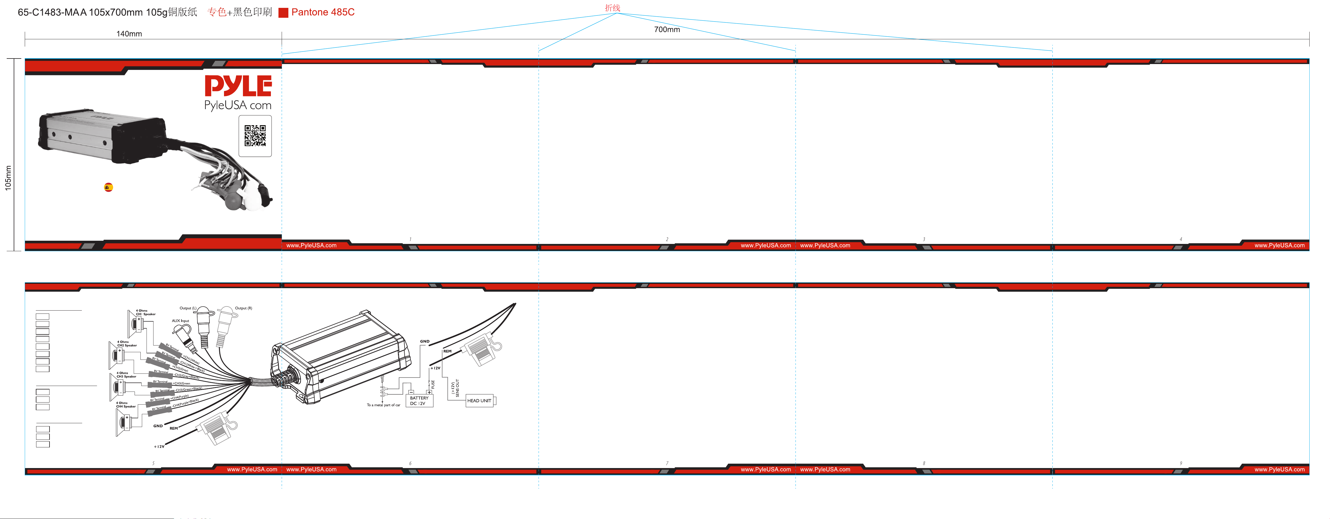
Speaker Output
Level Input/Output
Power
+CH1
White
+CH2
+CH3
-CH2
Grey
-CH1
White+Black
Grey+Black
Green
+CH4
Purple
-CH4
Purple+Black
IN
Black(AUX)
OUT White (L)
OUT Red (R)
+ 12V Red
GND
Black
REM
Blue
-CH3
Green+Black
Visit Our Website
SCAN ME
PyleUSA.com
UKUSA
Este amplicador de potencia ha sido diseñado para proporcionar un rendimiento de alta calidad con un mínimo de
mantenimiento. Sin embargo, su rendimiento solo será tan bueno como el cuidado y la calidad de los componentes
con los que se instale. Por lo tanto, le recomendamos que lea atentamente estas instrucciones para familiarizarse con el
producto y sus características. Antes de instalar el amplicador de potencia, lea atentamente este manual de
instrucciones. Las instrucciones para montar y conectar el conjunto deben seguirse con precisión. Si es necesario, se
debe consultar a un centro de servicio. Todas las conexiones para la alimentación de CC, la entrada de señal y las salidas
de altavoz se pueden realizar de forma fácil y segura mediante RCA y terminales atornillados.
Por favor, elija un lugar de montaje sin inuencias climáticas directas. Tenga en cuenta que el amplicador genera
calor, por lo que es necesario un lugar bien ventilado. De acuerdo con la construcción de su vehículo y embarcación
marina, el conjunto se puede fabricar con mucho cuidado para garantizar el rendimiento y la abilidad completos del
amplicador. Mantenga las conexiones de cables lo más cortas posible con dimensiones sucientes para minimizar las
pérdidas de energía y proporcionar una mayor salida de audio del sistema. Por razones de seguridad, enrute todo el
cableado de alimentación y de los altavoces utilizando los canales de cable de salida. Para minimizar el daño a los
cables, tenga cuidado de que no pasen metal con bordes alados. Coloque todos los cables lo más lejos posible de los
cables de encendido, los módulos en el maletero y debajo del tablero de llaves, ya que esto crea interferencias.
Agregue un fusible en el cable de alimentación (+) a una distancia de no más de 30 cm del polo positivo de la batería.
Mantenga la longitud de los cables de alimentación lo más corta posible. Es mejor usar cables de alimentación que
sean cortos y luego cables de altavoz más largos. Para reducir las interferencias, también preste atención a las
instrucciones.
• Esta unidad está diseñada para funcionar únicamente con tierra negativa de 12 a 14,50 voltios (CC).
• Utilice altavoces con una impedancia de 4 ohmios
• Evite instalar la unidad donde:
• Estaría sujeto a altas temperaturas, como la luz solar directa o el aire caliente del calentador.
• Estaría expuesto a la lluvia o a la humedad.
• Estaría sujeto al polvo o a la suciedad.
INTRODUCCIÓN
INSTRUCCIONES DE INSTALACIÓN
Features:
OPERACIÓN
PRECAUCIONES
WIRING INSTRUCTIONS
• Si su vehículo o embarcación está estacionado bajo la luz solar directa y hay un aumento considerable de la
temperatura dentro del automóvil, deje que la unidad se enfríe antes de funcionar.
• Por razones de seguridad, mantenga el volumen de su sistema de audio moderado para que pueda escuchar los
sonidos normales del tráco a una distancia razonable.
• No utilice la unidad con una batería automática débil, ya que su rendimiento óptimo depende de un voltaje de
alimentación de batería normal.
• Este amplicador de potencia emplea un circuito de protección para proteger los transistores y los altavoces si
el amplicador no funciona correctamente. No intente probar los circuitos de protección cubriendo el disipador
de calor o conectando cargas inadecuadas.
• Si esta unidad se coloca demasiado cerca de la radio de recursos, puede producirse una interferencia. En este
caso, separe el amplicador de la radio del automóvil.
• Al instalar la unidad horizontalmente, asegúrese de no cubrir las aletas del disipador de calor con la alfombra
del piso.
CONEXIÓN DE ALIMENTACIÓN
• El terminal de la batería (BATT) debe conectarse directamente al terminal positivo de la batería del vehículo para
proporcionar una fuente de voltaje adecuada y minimizar el ruido. Conectar el cable del terminal de la batería a cualquier
otro punto (como el bloque de fusibles) reducirá la potencia de salida y puede causar ruido y distorsión. Use solo un cable
de calibre # 12 o más grueso (calibre más pequeño #) para este cable y conéctelo al terminal de la batería después de que
se complete todo el resto del cableado.
CONEXIÓN A TIERRA
• La conexión del terminal de tierra (GND) también es fundamental para el correcto funcionamiento del amplicador.
Utilice un cable del mismo calibre que la conexión de alimentación (#B o más grueso) y conéctelo entre el terminal de
tierra (GND) del amplicador y una parte metálica del vehículo cerca del lugar de montaje. Este cable debe ser lo más
corto posible y cualquier pintura u óxido en el punto de conexión a tierra debe rasparse para proporcionar una
supercie metálica limpia a la que se pueda atornillar o atornillar el extremo del cable de tierra.
CONEXIÓN DE ENCENDIDO REMOTO
• El amplicador se enciende aplicando +12 V al terminal de encendido remoto (REM). El cable de este terminal debe
conectarse al cable de "Antena automática" de los recursos estéreo del vehículo o embarcación, lo que proporcionará
los +12 V solo cuando se enciendan los recursos estéreo. Si el estéreo del automóvil no proporciona un cable de
"antena automática", el cable de encendido remoto puede estar conectado a un terminal de "accesorio" o "radio" en
el bloque de fusibles del vehículo / o embarcación. Esto encenderá y apagará el amplicador con la llave de
encendido, independientemente de si los recursos estéreo están encendidos o apagados. El cable de encendido
remoto no transporta grandes corrientes. Por lo tanto, se puede usar alambre de calibre # 16 para esta aplicación.
CONEXIONES DE ALTAVOCES
• Dependiendo del tipo y la cantidad de altavoces utilizados con el amplicador, conéctelos a los terminales de los
altavoces según el diagrama de cableado correspondiente. Para la mayoría de las aplicaciones# Se debe usar alambre
de calibre 18 para los cables de los altavoces, pero en ningún caso más delgado que el calibre # 16. Para los cables
que exceden los 10 pies, se recomienda el calibre # 12. Al cablear los altavoces, preste mucha atención a la polaridad
de los terminales de los altavoces y asegúrese de que correspondan a la polaridad de los terminales correspondientes
del amplicador. No conecte a tierra ningún cable de altavoz al chasis del vehículo o embarcación.
GND (-)=CONEXIÓN A TIERRA
• Conecte el terminal GND a la tierra del chasis de su vehículo / o embarcación y cree el mejor contacto eléctrico y
mecánico. Al hacerlo, taladre un agujero en el chasis del vehículo o barco cerca del amplicador y luego elimine el
color, la suciedad o cualquier otra sustancia del punto de tierra. A continuación, je el extremo del cable con un
anillo añadido.
+ 12V = FUENTE DE ALIMENTACIÓN
• Conecte el terminal BATT al polo positivo de la batería con un cable conductor y agregue un fusible en el cable de
alimentación a una distancia de no más de 30 cm de la batería. El diámetro del cable conductor debe ser de al
menos 4 mm para una longitud de 3 m y de 6 mm para una longitud de 6 mt.
MANDO A DISTANCIA REM (ON/OFF)
• Conecte el terminal REM al conector de antena automática de la radio de su vehículo o barco. Ahora, al encender y
apagar la radio de su vehículo o barco. el amplicador se enciende y apaga automáticamente. Un diámetro de cable
de 0,5 mm2 es suciente.
• Amplicador Pro Audio PowerSport
• Sistema de amplicación de audio de 4 canales
• Construcción robusta de grado marino
• Conectores con clasicación impermeable y resistentes
a la intemperie
• Arnés de cableado de alimentación integrado
• Perfecto para instalaciones y aplicaciones personalizadas
• Capacidad para conectarse y transmitir audio desde
dispositivos externos
• Mini entrada de audio auxiliar de 3,5 mm con cable
• Conectividad de cableado de altavoces
• Preamplicador RCA a cualquier OEM /
fábrica hecho universal
Amplicador monobloque o de rango
completo
• Encendido anti-golpe
• SoftTurn Encendido/Apagado
• Circuitos de protección de sobrecarga y
energía
• Se utiliza para sistemas de sonido de
embarcaciones y vehículos móviles portátiles
& Portable Mobile Vehicle Sound Systems
Especicaciones técnicas:
• Potencia de salida: 1500 vatios máx.
• Potencia MÁXIMA: 4 x 375 vatios @ 4 ohmios
(4 x 190 vatios)
• Grado marino Grado de impermeabilidad: IP-65
• T.H.D: 0.1%
• Relación señal/ruido:> 95 dB
• Separación de canales: > 65 dB
• Respuesta de frecuencia: 10 - 40kHz
• Fusible: 20A
• Alimentación: DC 12V
• Dimensiones del amperio (largo x ancho x alto):
5.90" x 3.62" x 1.97" -pulgadas (14.9 x 9.19 x 5 cm)
• Se vende como: 1
Una vez que se haya instalado el amplicador y se hayan realizado todas las conexiones con cuidado y seguridad,
encienda la radio para que el amplicador se encienda automáticamente. Después de un breve período de encendido,
el amplicador alcanza su máximo rendimiento. Ahora sube el volumen lentamente usando el control de volumen de
la radio. Si no hay sonido o solo una reproducción distorsionada, apague la radio inmediatamente (el amplicador
también se apagará automáticamente) y verique si todas las conexiones se han realizado correctamente.
AMPLIFICADOR DE 4 CANALES RESISTENTE AL AGUA
PLMTR4A
Amplificador PowerSport de grado marino para
ATV, UTV, 4x4, Jeep (1500 vatios)
MANUAL DEL USUARIO
SPA
CABLES DE CONEXIÓN DE ENERGÍACONEXIONES DE ALTAVOCES
REEMPLAZO DE FUSIBLES
CÓMO PROCEDER EN CASO DE AVERÍAS INTERFERENCIA
NOTAS SOBRE LA FUENTE DE ALIMENTACIÓN:
• Conecte el cable de entrada de alimentación de +12 V solo después de que se hayan conectado todos los
demás cables.
• Asegúrese de conectar el cable de tierra de la unidad de forma segura a una parte metálica del vehículo o
embarcación.
• Una pérdida de conexión puede provocar un mal funcionamiento del amplicador.
• REM: La unidad se enciende aplicando +12 voltios a este terminal. Este terminal no consume corriente pesada
como los terminales de alimentación de remolque, por lo que es aceptable un cable de conexión más delgado. El
calibre estándar 1B está bien y el color estándar es rojo. Si la radio está equipada con un cable de control de antena
de alimentación, puede controlar este terminal.
• Si el cable de la antena de alimentación ya está en uso, aún puede empalmarlo. Con este método, la unidad se
encenderá automáticamente con la radio.
• Utilice el cable de la fuente de alimentación con un fusible conectado cuyo valor sea el mismo que el fusible original.
Coloque el fusible en el cable de la fuente de alimentación lo más cerca posible de la batería del automóvil.
• Durante una operación a plena potencia, la corriente máxima correrá a través del sistema. Por lo tanto, asegúrese de
que los cables que se conectarán a los terminales + 12V y GND de la unidad, respectivamente, deben ser más grandes
que el funcionamiento correcto del puente de calibre 18 (AWG.1B). Si solo hay señal mono disponible, se requiere
un adaptador "Y"
Si el fusible se funde, verique la conexión de alimentación y reemplace el fusible. Si el fusible vuelve a fundirse como
reemplazo, puede haber un mal funcionamiento interno. En este caso, consulte a su distribuidor.
• La unidad está sobrecalentada.
• Los terminales de los altavoces están en cortocircuito
ADVERTENCIA:
Utilice el fusible de amperaje especicado. El uso de un fusible de mayor amperaje puede causar daños graves.
Sin función:
• El cable de conexión no está conectado correctamente (=terminal+12V/GND/REM).
Asegúrese de que se hayan quitado todas las conexiones y el contacto mecánico y que se haya quitado la camisa.
El fusible está defectuoso: ¡preste atención al valor correcto del nuevo fusible!
CIRCUITO DE PROTECCIÓN:
Este amplicador está provisto de un circuito de protección que funciona en los siguientes casos cuando:
•
Los cables positivo y negativo del cable del altavoz tienen contacto, lo que elimina el cortocircuito.
Preste atención, solo se permite un altavoz de carga de 4 ohmios.
No se permite una conexión de altavoz de 2 ohmios o menos impedancia.
Sin sonido:
• El cable del altavoz o el enchufe del altavoz no están conectados correctamente.
Mala calidad de sonido (distorsiones):
• Los altavoces están sobrecargados, por lo tanto, baje el nivel de volumen y verique las posiciones de control de
volumen
Sin sonido estéreo y con un bajo débil:
• Los cables de los altavoces (+) y (-) están mezclados, la unidad cableada está desfasada.
Todos los cables pueden originar y crear interferencias. El cable de alimentación y el cable de audio Cinch/RCA son
muy propensos a interferencias; Los cables remotos son menos propensos. A menudo hay interferencias causadas
por el generador (tuberías), el encendido (agrietamiento) u otras partes electrónicas del vehículo o embarcación.
La mayoría de estos problemas se pueden eliminar con un cableado correcto y cuidadoso. Al hacerlo, aquí están
las siguientes pautas:
• Utilice únicamente un cable de audio apantallado para el cableado entre la entrada de "bajo nivel" del amplicador
y la salida RCA o DIN de la radio.
• En caso de que todas estas medidas no tengan éxito, el uso de un aislador de bucle de tierra puede resolver el
problema
• Para reducir la resistencia de contacto y los contactos defectuosos y sueltos, suelde los extremos de los cables o
utilice extremos de cables multipolares, terminales de pala u otros. Los terminales de pala chapados en oro están
libres de corrosión y tienen la resistencia de contacto más baja.
• Si hay zumbidos, use cables de tierra más gruesos o agregue más cables de tierra al chasis.
• Si hay ruidos del sistema eléctrico del automóvil, agregue un estrangulador de supresión de interferencias en el
cableado de alimentación.
• Si hay pastillas de fuentes eléctricas externas en los cables de los altavoces, divida los cables del núcleo y gírelos
juntos.
• Evite los bucles de tierra colocando el cableado de tierra de todos los componentes en un punto central en forma
de estrella. Puede encontrar el mejor punto central para medir el voltaje directamente en la batería. Ahora compare
este valor de voltaje con el punto de tierra elegido y el terminal (+) del amplicador. Si el voltaje medido es solo
ligeramente diferente, ha encontrado la central correcta. De lo contrario, hay que buscar otro punto. Debe medir con
el punto de encendido de la toma de tierra que se está conectando y los consumidores adicionales encendidos
(calefacción y luz de la luneta trasera).
• Coloque los cables de señal, altavoz y alimentación por separado con suciente distancia entre sí y también entre
sí del cable del automóvil. Si no es posible, puede tender el circuito y el cable de tierra junto con los cables serie. El
cable de audio y del altavoz debe estar lo más lejos posible de ellos. El cable REM a la salida automática de la antena
de la radio se puede tender junto con los cables de señal.
Salida de altavoz
Salida de entrada de nivel
Power
+CH1
Blanco
+CH2
+CH3
-CH2
Gris
-CH1
Blanco+Negro
Gris+Negro
Verde
+CH4
Morado
-CH4
Morado+Negro
IN
Negro (AUX)
OUT
Blanco (L)
OUT Rojo (R)
+ 12V Rojo
GND
Negro
REM
Azul
-CH3
Verde+Negro
Visite nuestro
sitio web
ESCANÉAME
PyleUSA.com
Cet amplicateur de puissance a été conçu pour orir des performances de haute qualité avec un entretien minimal.
Cependant, ses performances ne seront aussi bonnes que le soin et la qualité des composants avec lesquels il est
installé. Veuillez lire attentivement ces instructions pour vous familiariser avec le produit et ses fonctionnalités. Avant
d'installer l'amplicateur de puissance, veuillez lire attentivement ce manuel d'instructions. Les instructions de
montage et de connexion doivent être suivies précisément. Si nécessaire, consultez un centre de service. Toutes les
connexions pour l'alimentation CC, l'entrée de signal et les sorties de haut-parleurs peuvent être eectuées facilement
et en toute sécurité à l'aide de connecteurs RCA et de bornes à vis.
Veuillez choisir un emplacement de montage sans inuence directe de la météo. Gardez à l'esprit que l'amplicateur
génère de la chaleur, donc un endroit bien ventilé est nécessaire. Selon la construction de votre véhicule ou de votre
bateau, l'installation doit être eectuée avec soin pour garantir les performances et la abilité de l'amplicateur.
Maintenez les connexions des ls aussi courtes que possible avec des dimensions susantes pour minimiser les pertes
de puissance et fournir une sortie audio plus élevée pour le système. Faites passer tous les câblages d'alimentation et
de haut-parleurs en utilisant les canaux de câbles existants pour plus de sécurité. Assurez-vous qu'ils ne passent pas
près de métal tranchant pour éviter les dommages aux câbles. Éloignez tous les câbles autant que possible des câbles
d'allumage, des modules dans le core et sous le tableau de bord, car cela peut causer des interférences. Ajoutez un
fusible dans le câble d'alimentation (+) à une distance de 30 cm maximum du pôle positif de la batterie. Gardez la
longueur des ls d'alimentation aussi courte que possible. Il est préférable d'utiliser des câbles d'alimentation courts
puis des câbles de haut-parleur plus longs. Pour réduire les interférences, suivez attentivement les instructions.
• Cet appareil est conçu uniquement pour une utilisation en négatif à 12-14,50 volts (CC).
• Utilisez des haut-parleurs avec une impédance de 4 ohms.
• Évitez d'installer l'unité là où:
•
Elle serait exposée à des températures élevées, telles que la lumière directe du soleil ou l'air chaud du chauage.
• Elle serait exposée à la pluie ou à l'humidité.
• Elle serait exposée à la poussière ou à la saleté.
INTRODUCTION
INSTRUCTIONS D'INSTALLATION
Fonctionnalités:
FONCTIONNEMENT
PRÉCAUTIONS
INSTRUCTIONS DE C BLAGE
• Si votre véhicule ou votre bateau est garé en plein soleil et que la température à l'intérieur de la voiture augment
considérablement, laissez l'unité refroidir avant de l'utiliser.
• Pour des raisons de sécurité, maintenez le volume de votre système audio modéré pour pouvoir encore entendre
les bruits de la circulation normale à une distance raisonnable.
• N'utilisez pas une batterie de voiture faible ; ses performances optimales dépendent d'une tension d'alimentation
de batterie normale.
• Cet amplicateur de puissance utilise un circuit de protection pour protéger les transistors et les haut-parleurs en
cas de dysfonctionnement. Ne testez pas les circuits de protection en recouvrant le dissipateur thermique ou en
connectant des charges incorrectes.
• Si cette unité est placée trop près de la radio, des interférences peuvent se produire. Dans ce cas, séparez
l'amplicateur de la radio de la voiture.
• Lors de l'installation de l'unité horizontalement, assurez-vous de ne pas recouvrir les ailettes du dissipateur
thermique avec le tapis de sol.
CONNEXION D'ALIMENTATION
•
La borne de batterie (BATT) doit être connectée directement à la borne positive de la batterie du véhicule pour
fournir une source de tension adéquate et minimiser le bruit. Connecter la borne de batterie à tout autre point
(comme le bloc de fusibles) réduira la puissance de sortie et peut causer du bruit et de la distorsion. Utilisez
uniquement un l de calibre #12 ou plus épais (calibre plus petit #) pour ce câble et connectez-le à la borne de
batterie après avoir terminé tous les autres câblages.
CONNEXION À LA MASSE
•
La connexion de la borne de masse (GND) est essentielle au bon fonctionnement de l'amplicateur. Utilisez un l
du même calibre que la connexion d'alimentation (#8 ou plus épais) et connectez-le entre la borne de masse de
l'amplicateur (GND) et une partie métallique du véhicule proche de l'emplacement de montage. Ce l doit être
aussi court que possible, et toute peinture ou rouille au point de mise à la masse doit être grattée pour fournir une
surface métallique propre à laquelle l'extrémité du l de masse peut être vissée ou boulonnée.
CONNEXION DE MISE EN MARCHE À DISTANCE
• L'amplicateur est activé en appliquant +12V à la borne de mise en marche à distance (REM). Le l menant à cette
borne doit être connecté au l "Auto-Antenne" provenant des ressources stéréo du véhicule ou du bateau, qui
fournira le +12V uniquement lorsque les ressources stéréo sont allumées. Si la stéréo de voiture n'ore pas de l
"Auto-Antenne", le l de mise en marche à distance peut être câblé à une borne "Accessoire" ou "Radio" dans le bloc
de fusibles du véhicule ou du bateau. Cela allumera et éteindra l'amplicateur avec la clé de contact, que les
ressources stéréo soient allumées ou non. Le l de mise en marche à distance ne transporte pas de gros courants.
Ainsi, un l de calibre #16 peut être utilisé pour cette application.
CONNEXIONS DES
HAUT-PARLEURS
• Selon le type et le nombre de haut-parleurs utilisés avec l'amplicateur, raccordez-les aux bornes des haut-parleurs
conformément au schéma de câblage approprié. Pour la plupart des applications, un l de calibre #18 devrait être
utilisé pour les ls des haut-parleurs, mais il ne doit pas être plus mince que le calibre #16. Pour des ls de plus de
10 pieds, un calibre #12 est recommandé. Lors du câblage des haut-parleurs, veuillez prêter attention à la polarité
des bornes des haut-parleurs et assurez-vous qu'elles correspondent à la polarité des bornes correspondantes sur
CONNEXION À LA MASSE (-)
• Connectez la borne de masse (GND) au châssis de votre véhicule ou de votre bateau pour assurer un contact
électrique et mécanique optimal. Percez un trou près de l'amplicateur dans le châssis, puis nettoyez la zone pour
obtenir une surface métallique propre. Fixez ensuite l'extrémité du câble avec une cosse en anneau à l'aide d'unevis.
Assurez-vous que le câble est susamment épais (au moins 4 mm) et aussi court que possible. Les câbles de masse
de la radio et des autres équipements doivent également être connectés au même point de masse.
ALIMENTATION (+12V)
• Connectez la borne de batterie (BATT) au pôle positif de la batterie à l'aide d'un câble de liaison et ajoutez un fusible
à une distance maximale de 30 cm de la batterie. Le câble de liaison doit avoir un diamètre d'au moins 4 mm pour
une longueur de 3 m et de 6 mm pour une longueur de 6 m.
TÉLÉCOMMANDE (REM)
• Connectez la borne de télécommande (REM) au connecteur d'antenne automatique de votre radio de véhicule ou
de bateau. L'amplicateur s'allumera et s'éteindra automatiquement lorsque vous allumez ou éteignez la radio.
Un câble d'un diamètre de 0,5 mm2 est susant.
• Amplicateur Pro Audio PowerSport
• Système d'amplicateur audio à 4 canaux
• Construction robuste de qualité marine
• Connecteurs étanches et résistants aux intempéries
• Harnais de câblage d'alimentation intégré
• Parfait pour les installations et les applications
personnalisées
• Capacité de connexion et de diusion audio depuis
des appareils externes
• Entrée audio AUX mini 3,5 mm câblée
• Connectivité des ls des haut-parleurs
• Sortie pré-ampli RCA vers n'importe quel
amplicateur mono bloc universel OEM/
Factory ou à gamme complète
• Mise en marche anti-cliquetis
• Mise en marche/arrêt en douceur
• Circuit de protection contre la surchargeet
la surtension
• Utilisé pour les systèmes audio de véhicules
nautiques et mobiles portables
Spécications techniques:
• Puissance de sortie : 1500 watts MAX.
• Puissance MAX : 4 x 375 watts @ 4 ohms (4 x 190 watts)
• Classication étanche de qualité marine : IP-65
• DHT : 0,1 %
• Rapport S/B : > 95 dB
• Séparation des canaux : > 65 dB
• Réponse en fréquence : 10 - 40 kHz
• Fusible : 20 A
• Alimentation : CC 12 V
• Dimensions de l'ampli (L x l x H) :
5,90" x 3,62" x 1,97"-pouces (14.9 x 9.19 x 5 cm)
• Nombre de pièces vendues : 1
Une fois que l'amplicateur est installé et que toutes les connexions sont eectuées avec soin et sécurité, allumez la
radio pour que l'amplicateur s'active automatiquement. Après une brève période de mise sous tension, l'amplica-
teur atteint sa pleine performance. Augmentez ensuite progressivement le volume à l'aide du contrôle de volume de
la radio. S'il n'y a pas de son ou si le son est déformé, éteignez immédiatement la radio. L'amplicateur s'éteindra
également automatiquement. Vériez ensuite si toutes les connexions sont correctes.
AMPLIFICATEUR ÉTANCHE À 4 CANAUX PLMTR4A
PLMTR4A
Amplificateur étanche de qualité marine pour
VTT, UTV, 4x4, Jeep (1500 watts)
MANUEL D'UTILISATION
CONDUITS DE CONNEXION D'ALIMENTATIONCONNEXIONS DES HAUT-PARLEURS
REMPLACEMENT DU FUSIBLE
COMMENT PROCÉDER EN CAS DE DÉFAILLANCES INTERFÉRENCES
REMARQUES SUR L'ALIMENTATION:
• Connectez d'abord le câble d'alimentation +12V après tous les autres câbles.
• Assurez-vous que le l de masse de l'unité est solidement connecté à une partie métallique du véhicule ou du
bateau pour éviter tout dysfonctionnement de l'amplicateur.
• REM: L'unité s'allume en appliquant +12 Volts à cette borne. Cette borne ne tire pas de courants lourds
comme les deux bornes d'alimentation, donc un l de connexion plus mince est acceptable. Un calibre
standard de 18 est susant, et la couleur standard est le rouge. La radio peut alimenter cette borne si elle
est équipée d'un l de commande d'antenne électrique. Si le l d'antenne électrique est déjà utilisé, vous
pouvez toujours le brancher dessus. Avec cette méthode, l'unité s'allumera automatiquement avec la radio.
• Utilisez le l d'alimentation avec un fusible attaché dont la valeur est identique à celle du fusible d'origine.
• Placez le fusible dans le l d'alimentation aussi près que possible de la batterie de la voiture.
• Pendant toute l'opération d'alimentation, un courant maximal circulera dans le système. Par conséquent,
assurez-vous que les ls connectés aux bornes +12V et GND de l'unité sont respectivement plus
importantsque du calibre 18 (AWG.18) pour un fonctionnement en pontage approprié. Si seul un signal
mono est disponible, un adaptateur "Y1" est nécessaire.
Si le fusible saute, vériez la connexion d'alimentation et remplacez le fusible. Si le fusible saute à nouveau
après remplacement, un dysfonctionnement interne peut survenir. Dans ce cas, consultez votre revendeur.
• l'unité surchaue.
• les bornes des haut-parleurs sont en court-circuit.
ATTENTION:
Utilisez le fusible d'ampérage spécié. L'utilisation d'un fusible d'ampérage plus élevé peut causer des
dommages graves.
Aucune fonction:
• Le câble de connexion n'est pas correctement branché (=borne +12V/GND/REM).
Assurez-vous que toutes les connexions, le contact mécanique et la gaine ont été retirés.
Le fusible est défectueux - faites attention à la valeur correcte d'un nouveau fusible !
CIRCUIT DE PROTECTION:
Cet amplicateur est équipé d'un circuit de protection qui fonctionne dans les cas suivants lorsque:
• Les ls plus et moins du câble du haut-parleur sont en contact, éliminant ainsi le court-circuit.
Si vous utilisez Attention, seul un haut-parleur de charge de 4 ohms est autorisé.
Aucune connexion de haut-parleur d'impédance de 2 ohms ou moins n'est autorisée.
Aucun son:
• Le câble ou la che du haut-parleur n'est pas correctement connecté.
Mauvaise qualité sonore (distorsions):
• Les haut-parleurs sont surchargés ; réduisez le niveau de volume et vériez les positions de commande de
volume.
Aucun son stéréo et des basses faibles :
• Les câbles de haut-parleur (+) et (-) sont mélangés, et l'unité est câblée hors phase.
Tous les câbles peuvent être sources et créateurs d'interférences. Le câble d'alimentation et le câble audio
Cinch/RCA sont très sujets aux interférences ; les câbles de télécommande le sont moins. Les interférences sont
souvent causées par le générateur (ronement), l'allumage (crépitement) ou d'autres composants électroniques
du véhicule ou du bateau. La plupart de ces problèmes peuvent être éliminés par un câblage correct et soigné.
Voici quelques directives à suivre :
• Utilisez uniquement un câble audio blindé pour le câblage entre l'entrée "niveau bas" de l'amplicateur et la
sortie RCA ou DIN de la radio.
• Si toutes ces mesures échouent, un isolateur de boucle de masse peut résoudre le problème.
• Pour réduire la résistance de contact et les mauvais contacts, soudez les extrémités des câbles ou utilisez des
embouts multicœurs, des bornes à languette ou autres. Les bornes à languette plaquées or sont exemptes de
corrosion et ont la plus faible résistance de contact.
• En cas de bruits de ronement, utilisez des câbles de mise à la masse plus épais ou ajoutez des câbles au châssis.
• En cas de bruits provenant de l'électricité de la voiture, ajoutez une bobine de suppression des interférences dans
le câblage d'alimentation.
• Si les câbles de haut-parleur captent des perturbations provenant de sources électriques externes, divisez les ls
de base et tordez-les ensemble.
• Évitez les boucles de masse en disposant les câbles de mise à la masse de tous les composants vers un point central
de manière en étoile. Vous pouvez trouver le meilleur point central en mesurant directement la tension à la batterie.
Comparez ensuite cette valeur de tension avec le point de masse choisi et la borne (+) de l'amplicateur. Si la tension
mesurée est seulement légèrement diérente, vous avez trouvé le bon point central. Sinon, vous devez chercher un
autre point. Vous devriez mesurer avec le point d'allumage pour la mise à la terre étant enclenchée et en allumant
également des consommateurs (chauage de la lunette arrière et lumière).
• Disposez séparément les câbles de signal, de haut-parleur et d'alimentation à une distance susante les uns des
autres et également des autres câbles de la voiture. Si cela n'est pas possible, vous pouvez disposer les câbles de
circuit et de mise à la masse ensemble avec les câbles série. Les câbles audio et de haut-parleur doivent être aussi
éloignés que possible de ceux-ci. Le câble REM vers la sortie d'antenne automatique de la radio peut être disposé
avec les câbles de signal.
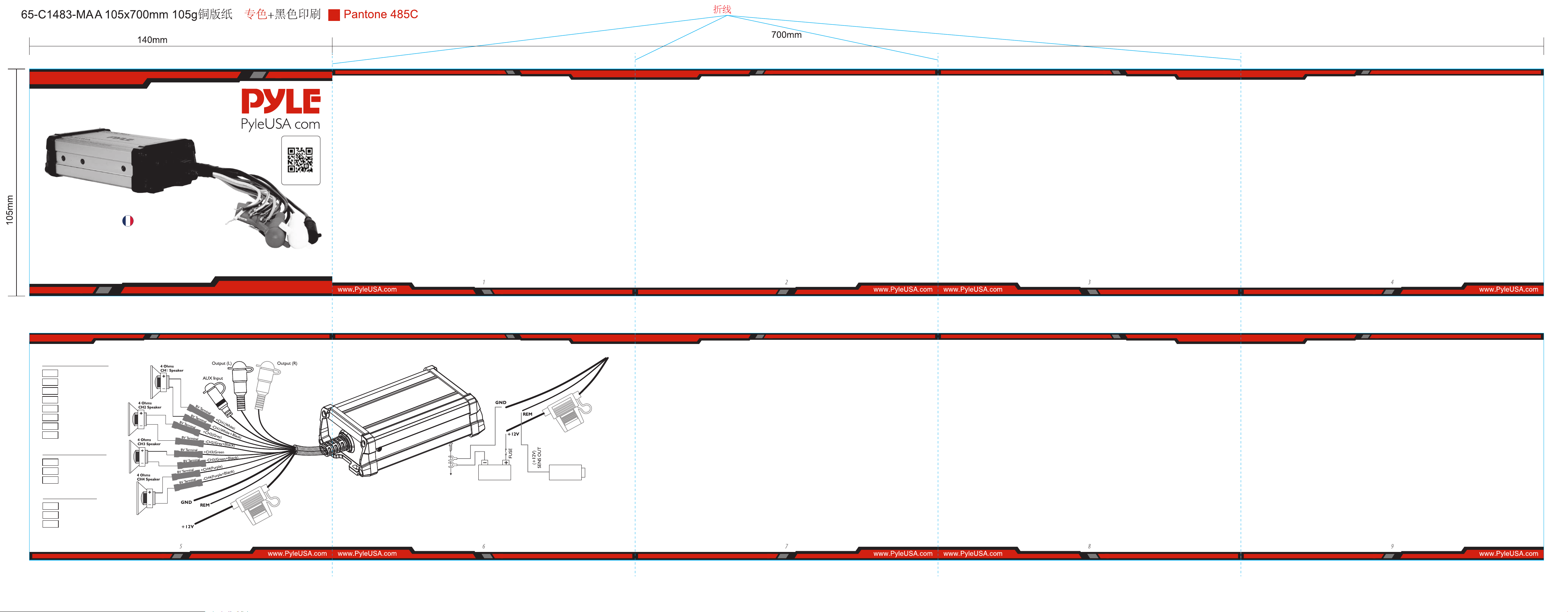
Sortie des haut-parleurs
Entrée/sortie de niveau
Alimentation
+CH1
Blanc
+CH2
+CH3
-CH2
Gris
-CH1
Blanc+Noir
Gris+Noir
Green
+CH4
Violet
-CH4
Violet+Noir
IN
Noir (AUX)
OUT
Blanc (L)
OUT Rouge (R)
+ 12V Rouge
GND
Noir
REM
Bleu
-CH3
Vert+Noir
Vers une partie
métallique de la voiture
UNITÉ
PRINCIPALE
BATTERIE CC
12V
Visitez notre site
Internet
SCANNE MOI
PyleUSA.com
FRE
Questo amplicatore è stato progettato per fornire prestazioni di alta qualità con una manutenzione minima. Tuttavia,
le sue prestazioni saranno proporzionali alla cura e alla qualità dei componenti con cui è installato. Si consiglia
pertanto di leggere attentamente le presenti istruzioni per familiarizzare con il prodotto e le sue caratteristiche. Prima
di installare l'amplicatore, leggere attentamente il presente manuale di istruzioni. Le istruzioni per il montaggio ed il
collegamento dell'apparecchio devono essere seguite con precisione. Se necessario, rivolgersi ad un centro di
assistenza.Tutti i collegamenti per l'alimentazione in c.c., l'ingresso del segnale e le uscite dei diusori possono essere
eseguiti in modo semplice e sicuro tramite terminali RCA e a vite.
Scegliere un luogo di montaggio privo di inuenze atmosferiche dirette. Si noti che l'amplicatore genera calore quindi
è necessario un luogo ben ventilato. In base alle caratteristiche costruttive del veicolo o dell'imbarcazione, l'installazi-
one necessita molta attenzione per garantire le prestazioni e l'adabilità dell'amplicatore. Mantenere i collegamenti
dei cavi il più corti possibile e di dimensioni sucienti per ridurre al minimo le perdite di potenza e garantire un'uscita
audio più elevata del sistema. Per motivi di sicurezza, tutti i cavi di alimentazione e dei diusori devono essere collegati
utilizzando i canali di uscita Per ridurre al minimo i danni ai cavi, fare attenzione a non farli passare su metallo con bordi
taglienti. Posare tutti i cavi il più lontano possibile dai cavi di accensione, dai moduli nel bagagliaio e sotto il cruscotto
della chiave, in quanto creano un'interferenza tra i cavi di alimentazione e quelli dei diusori. Aggiungere un fusibile
nel cavo di alimentazione (+) a una distanza non superiore a 30 cm dal polo positivo della batteria. Mantenere la
lunghezza dei cavi di alimentazione il più corta possibile. È preferibile utilizzare cavi di alimentazione corti e poi cavi
per diusori più lunghi. Per ridurre le interferenze, prestare attenzione anche alle istruzioni.
• Questa unità è progettata solo per il funzionamento a terra negativa a 12-14,50 Volt (CC).
• Utilizzare altoparlanti con un'impedenza di 4 Ohm.
• Evitare di installare l'unità in luoghi in cui:
• Sia soggetta a temperature elevate, ad esempio a causa della luce solare diretta o dell'aria calda del
riscaldamento.
• Sia esposta alla pioggia o all'umidità.
• Sarebbe soggetto a polvere o sporco.
INTRODUZIONE
INSTALLATION INSTRUCTIONS
Caratteristiche:
FUNZIONAMENTO
PRECAUZIONI
ISTRUZIONI PER IL CABLAGGIO
• Se il veicolo o l'imbarcazione sono parcheggiati alla luce diretta del sole e la temperatura all'interno dell'abitacolo
aumenta notevolmente, lasciare rareddare l'unità prima di metterla in funzione.
• Per motivi di sicurezza, mantenete il volume dell'impianto audio moderato in modo da poter sentire i normali rumori
del traco traco ad una distanza ragionevole.
• Non utilizzare l'unità con una batteria auto debole, poiché le sue prestazioni ottimali dipendono da una normale
tensione di alimentazione della batteria.
• Questo amplicatore di potenza impiega un circuito di protezione per proteggere i transistor e i diusori in caso di
malfunzionamento dell'amplicatore. Non tentare di testare i circuiti di protezione coprendo il dissipatore di calore
o collegando carichi impropri.
• Se l'unità viene collocata troppo vicina alla radio delle risorse, si può vericare un'interferenza. In questo caso,
separare l'amplicatore dall'autoradio.
• Quando si installa l'unità in orizzontale, assicurarsi di non coprire le alette del dissipatore con la moquette delpavimento.
COLLEGAMENTO ALL'ALIMENTAZIONE
• Il terminale della batteria (BATT) deve essere collegato direttamente al terminale positivo della batteria del
veicolo per fornire una fonte di tensione adeguata e ridurre al minimo i disturbi. Il collegamento del terminale
della batteria a qualsiasi altro (come il blocco fusibili) ridurrà la potenza erogata e potrebbe causare disturbi e
distorsioni. Utilizzare solo cavi di calibro #12 o più spesso (calibro più piccolo #) per questo cavo e collegarlo
al terminale della batteria dopo aver completato tutti gli altri cablaggi.
COLLEGAMENTO A TERRA
• Anche il collegamento del terminale di terra (GND) è fondamentale per il corretto funzionamento
dell'amplicatore. Utilizzate un lo dello stesso calibro del collegamento di alimentazione (#8 o più spesso) e
collegarlo tra il terminale di terra (GND) dell'amplicatore ed una parte metallica del veicolo vicina alla
posizione di montaggio. Questo lo deve essere il più corto possibile e qualsiasi vernice o ruggine nel punto
di messa a terra deve essere raschiata via per fornire una supercie metallica pulita su cui avvitare o imbullonare
l'estremità del lo di terra.
CONNESSIONE ALL'ACCENSIONE REMOTA
• L'amplicatore si accende applicando +12V al terminale di accensione remota (REM). Il cavo di collegamento
a questo terminale deve essere collegato al cavo "Auto-Antenna" dello stereo del veicolo o dell'imbarcazione,
che fornirà i +12V solo quando lo stereo è acceso. Se l'autoradio non fornisce un cavo "Auto-Antenna", il cavo di
accensione a distanza può essere collegato a un terminale "Accessorio" o "Radio" nella centralina del
veicolo/imbarcazione. In questo modo l'amplicatore si accende e si spegne con la chiave di accensione,
indipendentemente dal fatto che le risorse dello stereo siano accese o spente.Il cavo di accensione a distanza
non trasporta grandi correnti. Per questo motivo si può utilizzare un cavo di calibro #16.
COLLEGAMENTI DEGLI ALTOPARLANTI
• A seconda del tipo e del numero di altoparlanti utilizzati con l'amplicatore, collegarli ai terminali come da
schema di cablaggio appropriato. Per la maggior parte delle applicazioni si dovrebbe usare un cavo di calibro
#18 per i cavi degli altoparlanti, ma in nessun caso più sottile di un calibro # 16. Per i cavi superiori a 3 metri si
consiglia il calibro #12. Quando si cablano gli altoparlanti, prestare molta attenzione alla polarità dei terminali
ed accertarsi che corrispondano alla polarità dei terminali corrispondenti dell'amplicatore. Non collegare a
terra i cavi dei diusori al telaio del veicolo o dell'imbarcazione.
GND (-) = COLLEGAMENTO A TERRA
• Collegare il terminale GND alla massa del telaio del veicolo o dell'imbarcazione e fare attenzione al miglior contatto
elettrico e meccanico. Per fare ciò, praticare un foro nel telaio del veicolo/imbarcazione vicino all'amplicatore, quindi
rimuovere colore, sporcizia o qualsiasi altra sostanza dal punto di massa. Successivamente, ssare l'estremità del cavo
con il terminale ad anello aggiunto utilizzando una vite. Assicurarsi che il collegamento a terra sia il più corto possibile
e che il diametro del cavo sia suciente (min. 4 mm). I cavi di messa a terra della radio e di tutte le altre parti
dell'apparecchiatura, come ad esempio equalizzatore, crossover attivo o altri amplicatori, allo stesso punto di
messa a terra.
+ 12V = ALIMENTAZIONE
• Collegare il terminale BATT al polo positivo della batteria con un cavo e aggiungere un fusibile nel cavo di
alimentazione a una distanza non superiore a 30 cm dalla batteria. Il diametro del cavo deve essere di almeno
4 mm per una lunghezza di 3 m e di 6 mm" per una lunghezza di 6 m.
TELECOMANDO REM (ON/OFF)
• Collegare il terminale REM al connettore dell'antenna automatica della radio del veicolo o dell'imbarcazione.
Ora, quando si accende e si spegne l'amplicatore si accende e si spegne automaticamente. È suciente un
diametro del cavo di 0,5 mm.
• Amplicatore Pro Audio PowerSport
• Sistema di amplicazione audio a 4 canali
• Costruzione robusta di livello marino
• Connettori impermeabili e resistenti alle intemperie
• Cablaggio di alimentazione integrato
• Perfetto per installazioni e applicazioni personalizzate
• Possibilità di collegare e trasmettere l'audio da
dispositivi esterni
• Ingresso audio AUX mini 3,5 mm cablato
• Connettività per il cablaggio degli altoparlanti
• Uscita RCA preamplicata per qualsiasi
OEM / Universale prodotto in fabbrica
Amplicatore Blocco mono / o amplicatore
a gamma completa
• Accensione antirombo
• Accensione/spegnimento graduale
• Circuito di protezione da sovraccarico
ealimentazione
• Utilizzato per imbarcazioni e Sistemi audio
portatili per veicoli
Speciche Tecniche:
• Potenza di uscita: 1500 Watt MAX
• Potenza massima: 4.x 375 Watt a 4 Ohm
(4x 190 Watt)
• Grado di impermeabilità marina: IP-65
• T.H.D.: 0,1%
• Rapporto S/N : > 95 dB
• Separazione dei canali: > 65 dB
• Risposta in frequenza: 10 - 40kHz
• Fusibile: 20A
• Alimentazione: DC 12V
• Dimensioni dell'amplicatore (L x W x H):
5,90" x 3,62" x 1,97" pollici (14,9 x 9,19 x 5 cm)
• Venduto come: 1
Dopo che l'amplicatore è stato installato e tutti i collegamenti sono stati eseguiti con cura e sicurezza, accendete la
radio in modo che l'amplicatore si accenda automaticamente. Dopo un breve periodo di accensione, l'amplicatore
raggiunge le sue prestazioni. Ora alzate lentamente il volume utilizzando il comando del volume della radio. Se non si
sente alcun suono o se c'è solo una riproduzione distorta, spegnete immediatamente la radio - anche l'amplicatore si
spegnerà automaticamente - e controllate che tutti i collegamenti siano stati eseguiti correttamente.
Amplificatore impermeabile a 4 canali
PLMTR4A
Amplificatore PowerSport di qualità marina per ATV,
UTV, 4x4, Jeep (1500 Watt)
MANUALE UTENTE
CAVI DI COLLEGAMENTO ALL'ALIMENTAZIONECOLLEGAMENTO ALTOPARLANTI
SOSTITUZIONE DEI FUSIBILI
COME PROCEDERE IN CASO DI GUASTI INTERFERENZA
NOTE SULL'ALIMENTATORE:
• Collegare il cavo di ingresso dell'alimentazione +12V solo dopo aver collegato tutti gli altri cavi,
• Assicurarsi di collegare saldamente il lo di terra dell'unità a una parte metallica del veicolo/imbarcazione.
• Un collegamento errato potrebbe causare un malfunzionamento dell'amplicatore.
• REM: L'unità si accende applicando +12 Volt a questo terminale. Questo terminale non assorbe molta corrente
come i terminali di alimentazione a traino, per cui è accettabile un lo di collegamento più sottile. Va bene un
lo standard da 18 gauge e il colore standard è rosso. Se la radio è dotata di un cavo di controllo dell'antenna
di potenza, può pilotare questo terminale. Se il lo dell'antenna di potenza è già in uso, è possibile comunque
eettuare una giuntura. Con questo metodo, l'unità si accenderà automaticamente con la radio.
• Utilizzare il cavo di alimentazione con un fusibile il cui valore è uguale a quello del fusibile originale.
• Posizionare il fusibile nel cavo di alimentazione il più vicino possibile alla batteria dell'auto.
• Durante il funzionamento a piena potenza, il sistema sarà attraversato da una corrente massima. Pertanto,
assicurarsi che i cavi da collegare rispettivamente ai terminali +12V e GND dell'unità siano di calibro superiore
a 18 (AWG.18) per un corretto funzionamento a ponte. Se è disponibile solo il segnale mono, è necessario un
adattatore a "Y".
Se il fusibile si brucia, controllare il collegamento di alimentazione e sostituire il fusibile. Se il fusibile si brucia di
nuovo dopo la sostituzione, è possibile che si sia vericato un malfunzionamento interno. In questo caso,
• l'unità si surriscalda.
• i terminali dei diusori sono in cortocircuito.
AVVERTENZA:
Utilizzare il fusibile di amperaggio specicato. L'uso di un fusibile di amperaggio superiore può causare gravi
danni.
Nessuna funzione:
• Il cavo di collegamento non è collegato correttamente (=terminale +12V/GND/REM).
Assicurarsi che tutti i collegamenti e la meccanica facciano contatto e che la guaina sia stata rimossa.
Il fusibile è difettoso: prestare attenzione al valore corretto di un nuovo fusibile!
CIRCUITO DI PROTEZIONE:
Questo amplicatore è dotato di un circuito di protezione che interviene nei seguenti casi:
• I li positivo e negativo del cavo dell’altoparlante sono in contatto, eliminando così il cortocircuito.
Se si utilizza un altoparlante con carico di 4 ohm, è possibile utilizzarlo solo con un carico di 4 ohm.
Non è consentito il collegamento di altoparlanti con impedenza di 2 chm o inferiore.
Non c'è audio:
• Il cavo o la spina degli altoparlanti non sono collegati correttamente.
Scarsa qualità del suono (distorsioni):
• I diusori sono sovraccarichi, quindi abbassare il livello del volume e controllare le posizioni del controllo del
volume.
Nessun suono stereo e bassi deboli:
• I cavi degli altoparlanti (+) e (-) sono invertiti, l'unità è cablata fuori fase.
Tutti i cavi possono generare e creare interferenze. Il cavo di alimentazione e il cavo audio Cinch/RCA sono molto
inclini alle interferenze; i cavi remoti sono meno soggetti. Spesso le interferenze sono causate dal generatore
(tubature), accensione (crepe) o da altre parti elettroniche del veicolo o dell'imbarcazione. La maggior parte di
questi problemi può essere eliminata con un cablaggio corretto e attento. A tale scopo, ecco le seguenti linee
guida:
• Per il cablaggio tra l'ingresso a basso livello dell'amplicatore e l'uscita RCA o DIN della radio, utilizzare esclusivamente
un cavo audio schermato.
• Se tutti questi accorgimenti non dovessero avere successo, l'uso di un isolatore di loop di terra potrebbe risolvere il
problema.
• Per ridurre la resistenza di contatto e i contatti difettosi e allentati, saldare le estremità dei cavi o utilizzare terminali
di cavi multipli, terminali a forcella o altro. I terminali a forcella placcati in oro sono esenti da corrosione e presentano
la più bassa resistenza di contatto.
• In caso di ronzio, utilizzare cavi di massa più spessi o aggiungere altri cavi di massa al telaio.
• Se ci sono rumori provenienti dall'impianto elettrico dell'auto, aggiungere una bobina di soppressione delle
interferenze nel cablaggio di alimentazione.
• Se nei cavi degli altoparlanti sono presenti pick-up da fonti elettriche esterne, dividere i conduttori e attorcigliarli
insieme.
• Per evitare i loop di massa, è necessario che il cablaggio di terra di tutti i componenti sia collegato ad un punto
centrale, in modo da formare una stella. È possibile trovare il punto centrale migliore misurando la tensione
direttamente sulla batteria. Ora confrontate questo valore di tensione con il punto di massa scelto e il terminale (+)
dell'amplicatore. Se la tensione misurata è solo leggermente dierente, si è trovato il punto centrale corretto. In
caso contrario, è necessario cercarne un altro. Si dovrebbe misurare con il punto di accensione per la terra acceso e
con le utenze aggiuntive accese (lunotto termico e luci).
• Posare i cavi di segnale, diusori e alimentazione separatamente, ad una distanza suciente l'uno dall'altro e anche
da ogni altro cavo dell'auto. Se non è possibile, si può posare il cavo di circuito e di terra insieme ai cavi seriali. I cavi
audio e degli altoparlanti devono essere il più lontano possibile da questi. Il cavo REM per l'uscita dell'antenna
automatica della radio può essere posato insieme ai cavi di segnale.
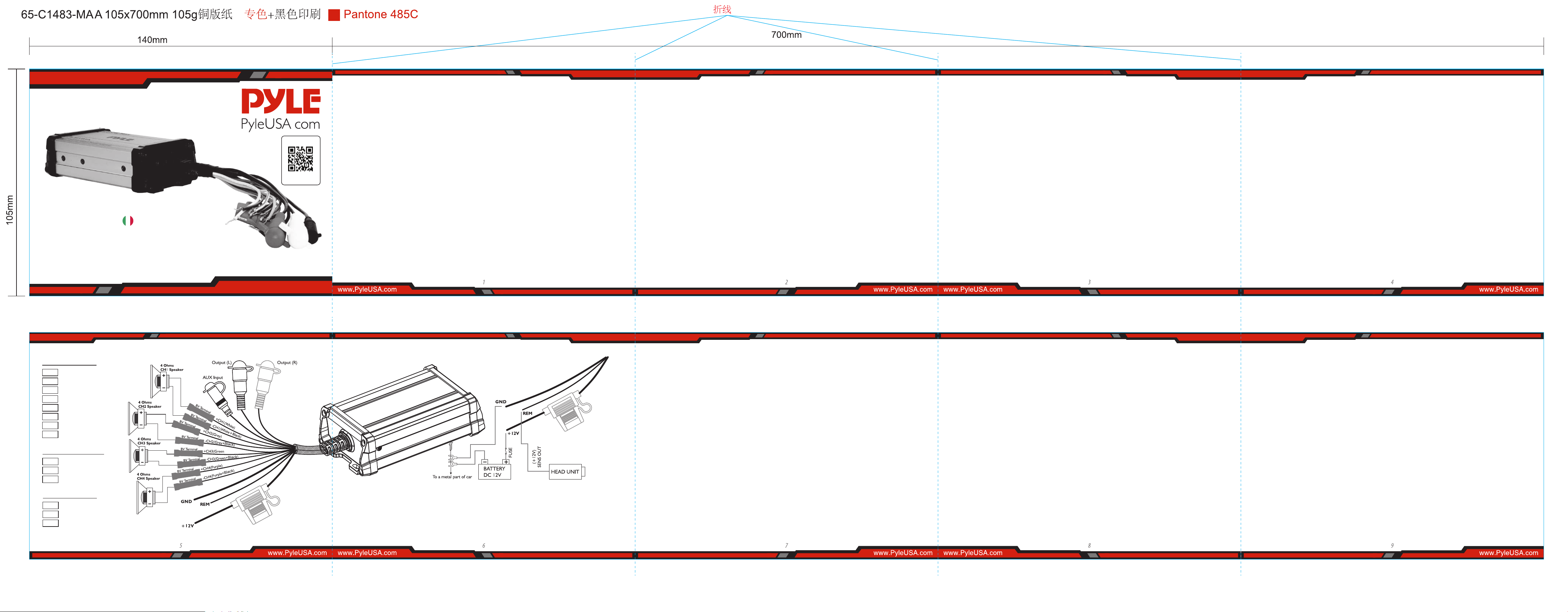
Uscita altoparlante
Livello Ingresso/Uscita
Potenza
+CH1
Bianco
+CH2
+CH3
-CH2
Grigio
-CH1
Bianco+Nero
Grigio+Nero
Verde
+CH4
Viola
-CH4
Viola+Nero
IN Nero (AUX)
OUT Bianco (L)
OUT Rosso (R)
+ 12V Rosso
GND
Nero
REM
Blu
-CH3
Verde+Nero
ITA
Visitare il nostro
sito web
SCANSIONAMI
PyleUSA.com
Dieser Leistungsverstärker wurde so entwickelt, dass eine hochwertige Leistung bei minimalem Wartungsaufwand
erzielt wird. Die Leistung ist jedoch nur so gut wie die Sorgfalt und Qualität der Komponenten, mit denen sie installiert
wird. Wir empfehlen Ihnen daher, diese Anleitung sehr sorgfältig zu lesen, um sich mit dem Produkt und seinen
Funktionen vertraut zu machen. Bitte lesen Sie diese Anleitung vor der Installation des Leistungsverstärkers sorgfältig
durch. Die Anweisungen zur Installation und zum Anschluss des Geräts müssen genau befolgt werden. Falls
erforderlich, sollte ein Kundendienstzentrum hinzugezogen werden. Alle Anschlüsse für die Gleichstromversorgung,
den Signaleingang und die Lautsprecherausgänge können einfach und sicher über Cinch- und Schraubklemmen
vorgenommen werden.
Bitte wählen Sie einen Montageort ohne direkte Witterungseinüsse. Beachten Sie, dass der Verstärker Wärme erzeugt,
so dass ein gut belüfteter Ort notwendig ist. Je nach Bauart Ihres Fahrzeugs oder Bootes kann das Set sehr sorgfältig
hergestellt werden, um die volle Leistung und Zuverlässigkeit des Verstärkers zu gewährleisten. Halten Sie die
Kabelverbindungen so kurz wie möglich und ausreichend bemessen, um Leistungsverluste zu minimieren und eine
höhere Audioleistung des Systems zu gewährleisten. Verlegen Sie aus Sicherheitsgründen alle Strom- und
Lautsprecherkabel unter Verwendung der vorhandenen Kabelkanäle. Achten Sie darauf, dass die Kabel nicht über
scharfkantiges Metall geführt werden, um Beschädigungen zu vermeiden. Verlegen Sie alle Kabel so weit wie möglich
entfernt von den Zündkabeln, Modulen im Koerraum und unter dem Armaturenbrett, da diese Störungen
verursachen. Legen Sie eine Sicherung in das (+) Stromkabel in einem Abstand von höchstens 30 cm vom Pluspol der
Batterie. Halten Sie die Länge der Stromkabel so kurz wie möglich. Es ist besser, kurze Stromkabel und dann längere
Lautsprecherkabel zu verwenden. Um Störungen zu vermeiden, beachten Sie bitte auch die Anleitung.
• Dieses Gerät ist nur für den Betrieb mit negativer Masse und 12-14,50 Volt (DC) geeignet.
• Verwenden Sie Lautsprecher mit einer Impedanz von 4 Ohm.
• Stellen Sie das Gerät nicht an einem Ort auf:
• Es ist hohen Temperaturen ausgesetzt, z. B. durch direkte Sonneneinstrahlung oder heiße Heizungsluft.
• Es ist Regen oder Feuchtigkeit ausgesetzt.
• Es ist Staub und Schmutz ausgesetzt.
EINLEITUNG
INSTALLATIONSANLEITUNGEN
Besonderheiten:
BETRIEB
VORSICHTSMASSNAHMEN
ANSCHLUSSHINWEISE
• Wenn das Fahrzeug oder Boot in direktem Sonnenlicht geparkt ist und die Temperatur im Fahrgastraum
stark ansteigt, lassen Sie das Gerät abkühlen, bevor Sie es in Betrieb nehmen.
• Halten Sie die Lautstärke des Audiosystems aus Sicherheitsgründen moderat, so dass normaler Verkehrslärm
aus einer angemessenen Entfernung gehört werden kann.
• Verwenden Sie das Gerät nicht mit einer schwachen Autobatterie, da seine optimale Leistung von einer
normalen Batteriespannung abhängt.
• Der Verstärker verfügt über eine Schutzschaltung, die die Transistoren und Lautsprecher im Falle einer
Fehlfunktion des Verstärkers schützt. Versuchen Sie nicht, die Schutzschaltung durch Abdecken des
Kühlkörpers oder Anschließen ungeeigneter Lasten zu testen.
• Wenn das Gerät zu nahe am Betriebsmittel Radio aufgestellt wird, kann es zu Störungen kommen. Trennen
Sie in diesem Fall den Verstärker vom Autoradio.
• Achten Sie beim horizontalen Einbau des Geräts darauf, dass die Kühlrippen nicht durch den Bodenteppich
verdeckt werden.
STROMANSCHLUSS
• Die Batterieklemme (BATT) muss direkt an den Pluspol der Fahrzeugbatterie angeschlossen werden, um eine
ausreichende Spannungsquelle zu schaen und Störungen zu vermeiden. Der Anschluss des Batteriepols an
einen anderen Punkt (z. B. an den Sicherungsblock) reduziert die Ausgangsleistung und kann zu Rauschen und
Verzerrungen führen. Verwenden Sie für dieses Kabel nur Draht der Stärke 12 oder dicker (kleinere Stärke #)
und schließen Sie es an den Pol der Batterie an, nachdem alle anderen Kabel fertiggestellt sind.
MASSEVERBINDUNG
• Der Anschluss der Masseklemme (GND) ist ebenfalls entscheidend für den korrekten Betrieb des Verstärkers.
Verwenden Sie ein Kabel mit dem gleichen Querschnitt wie der Stromanschluss (#8 oder dicker) und schließen
Sie es zwischen der Masseklemme (GND) des Verstärkers und einem Metallteil des Fahrzeugs in der Nähe des
Montageorts an. Dieses Kabel sollte so kurz wie möglich sein und jeglicher Lack oder Rost an der Massestelle
sollte abgekratzt werden, um eine saubere Metalloberäche zu erhalten, an die das Ende des Massekabels
geschraubt oder geschraubt werden kann.
FERNEINSCHALTANSCHLUSS
•
Der Verstärker wird durch Anlegen von +12 V an den Ferneinschaltanschluss (REM) eingeschaltet. Das Kabel an dieser
Klemme sollte mit dem „Auto-Antennen“-Kabel der Fahrzeug-/Boots-Stereoanlage angeschlossen werden, das die
+12 V nur dann liefert, wenn die Stereoanlage eingeschaltet ist. Wenn das Autoradio keine „Auto-Antennen“-Leitung
hat, kann die Ferneinschaltleitung mit einer „Zubehör“- oder „Radio“-Klemme im Sicherungsblock des Fahrzeugs oder
Bootes angeschlossen werden. Dadurch wird der Verstärker mit dem Zündschlüssel ein- und ausgeschaltet,
unabhängig davon, ob die Stereoanlage eingeschaltet ist oder nicht. Das Ferneinschaltkabel führt keine großen
Ströme. Daher kann für diese Anwendung Draht der Stärke 16 verwendet werden.
LAUTSPRECHERANSCHLÜSSE
• Je nach Art und Anzahl der mit dem Verstärker verwendeten Lautsprecher schließen Sie diese gemäß dem
entsprechenden Schaltplan an die Lautsprecheranschlüsse an. Für die meisten Anwendungen sollte Draht der Stärke
18 für die Lautsprecherkabel verwendet werden, aber auf keinen Fall dünner als Stärke 16. Für Kabel, die länger als
10 Fuß sind, wird Stärke 12 empfohlen. Achten Sie bei der Verkabelung der Lautsprecher auf die Polarität der
Klemmen an den Lautsprechern und stellen Sie sicher, dass sie mit der Polarität der entsprechenden Klemmen
am Verstärker übereinstimmen. Massieren Sie keine Lautsprecherkabel mit dem Chassis des Fahrzeugs oder Bootes.
GND (-) = MASSEANSCHLUSS
• Verbinden Sie die GND-Klemme mit der Chassis-Masse Ihres Fahrzeugs oder Bootes und achten Sie auf einen
optimalen elektrischen und mechanischen Kontakt. Bohren Sie dazu ein Loch in das Fahrzeug- oder Bootschassis in
der Nähe des Verstärkers und entfernen Sie Farbe, Schmutz oder andere Substanzen vom Massepunkt. Danach
befestigen Sie das Kabelende mit einem zusätzlichen Ringkabelschuh mit einer Schraube. Stellen Sie sicher, dass die
Masseverbindung so kurz wie möglich ist und dass der Kabeldurchmesser ausreichend ist (mindestens 4mm"). Führen
Sie die Massekabel des Radios und aller anderen Geräteteile, wie Equalizer, aktive Frequenzweiche oder andere
Verstärker, zum gleichen Massepunkt.
+ 12V = STROMVERSORGUNG
• Schließen Sie die BATT-Klemme mit einem Kabel an den Pluspol der Batterie an und fügen Sie eine Sicherung in das
Stromkabel ein, die nicht weiter als 30 cm von der Batterie entfernt sein darf. Der Durchmesser des Kabels soll
mindestens 4 mm' für eine Länge von 3 m und 6 mm“ für eine Länge von 6 m betragen.
REM (AN/AUS) FERNBEDIENUNG
• Schließen Sie die REM-Klemme an den automatischen Antennenanschluss Ihres Fahrzeug- oder Bootsradios an.
Nun schaltet sich der Verstärker beim Ein- und Ausschalten Ihres Fahrzeug-/Bootsfunkgeräts automatisch ein und
aus. Ein Kabeldurchmesser von 0,5 mm2 ist ausreichend.
• Pro Audio PowerSport-Verstärker
• 4-Kanal-Audio-Verstärkersystem
• Robuste Konstruktion in Marinequalität
• Wasserdichte und witterungsbeständige Steckverbinder
• Integrierter Kabelbaum für die Stromversorgung
• Perfekt für kundenspezische Installationen
und Anwendungen
• Anschlussmöglichkeit und Audio-Streaming von
externen Geräten
• Verkabelter Mini 3.5mm AUX-Audioeingang
• Anschlussmöglichkeit für Lautsprecherverkabelung
• Vorverstärker-Cinch-Ausgang für jeden
OEM-/Werks-Universal-Monoblock und/
oder Vollbereichsverstärker
• Anti-Thump-Einschaltung
• Sanftes Ein- und Ausschalten
• Überlast- und Leistungsschutzschaltung
• Für Wasserfahrzeuge und tragbare mobile
Fahrzeug-Soundsysteme
Technische Daten:
• Ausgangsleistung: 1500 Watt MAX
• MAX Leistung: 4.x 375 Watt @ 4 Ohm (4x 190 Watt)
• Wasserdichtigkeit nach Marineklasse: IP-65
• T.H.D: 0.1%
• S/N-Verhältnis : > 95 dB
• Kanaltrennung : > 65 dB
• Frequenzgang: 10 - 40kHz
• Absicherung: 20A
• Leistung: DC 12V
• Abmessungen des Verstärkers (L x B x H):
5.90“ x 3.62 ‚x 1.97‘ -Zoll (14.9 x 9.19 x 5 cm)
• Verkauft als: 1
Nachdem der Verstärker installiert und alle Verbindungen sorgfältig und sicher hergestellt wurden, schalten Sie das
Radio ein, so dass sich der Verstärker automatisch einschaltet. Nach einer kurzen Einschaltzeit erreicht der Verstärker
seine volle Leistung. Drehen Sie nun die Lautstärke mit dem Lautstärkeregler des Radios langsam hoch. Wenn kein
Ton oder nur eine verzerrte Wiedergabe zu hören ist, schalten Sie das Radio sofort aus - der Verstärker schaltet sich
ebenfalls automatisch ein - und überprüfen Sie, ob alle Anschlüsse korrekt vorgenommen wurden.
Wasserdichter 4-Kanal-Verstärker
PLMTR4A
Marine Grade PowerSport Verstärker für ATV,
UTV, 4x4, Jeep (1500 Watt)
BENUTZUNGSANLEITUNG
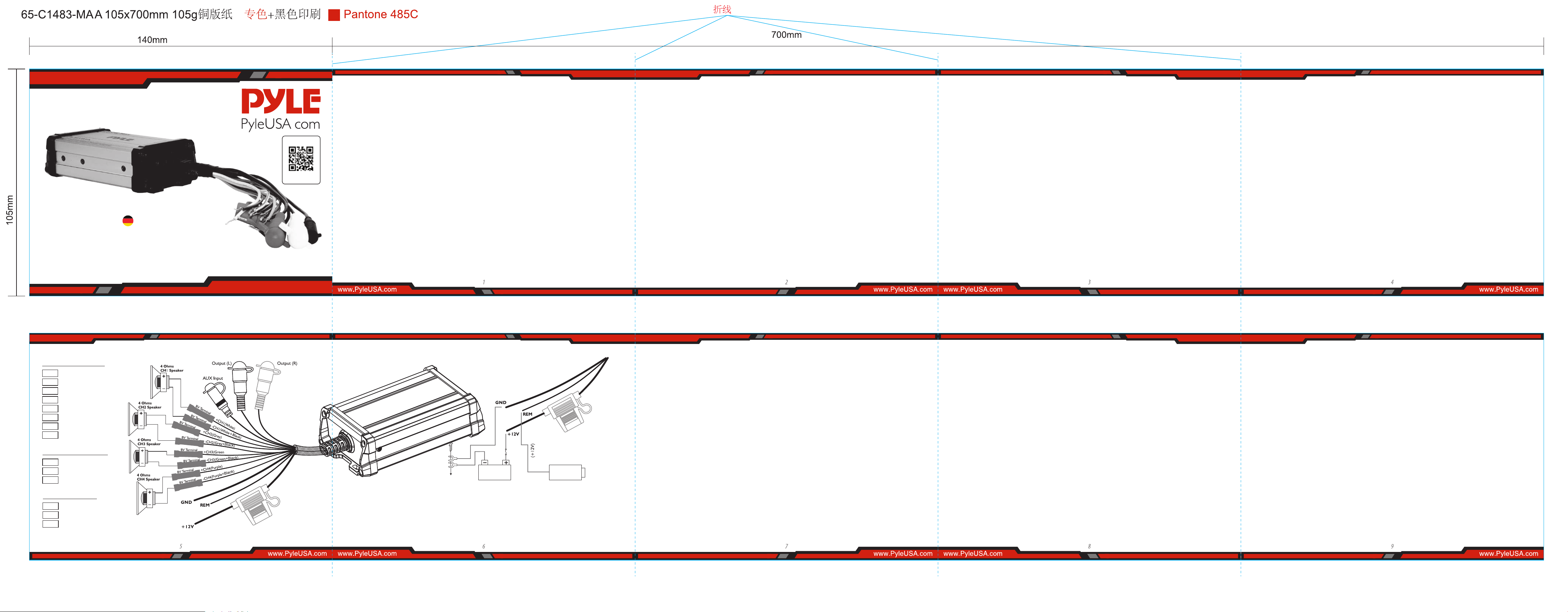
STROMANSCHLUSSKABELLAUTSPRECHERANSCHLUSS
SICHERUNGSERSATZ
VORGEHEN BEI STÖRUNGEN
STÖRUNGEN
HINWEISE ZUR STROMVERSORGUNG:
• Schließen Sie das +12-V-Eingangskabel erst an, nachdem alle anderen Kabel angeschlossen wurden,
• Achten Sie darauf, dass das Erdungskabel des Geräts fest mit einem Metallteil des Fahrzeugs/Boots
verbunden ist.
• Ein fehlerhafter Anschluss kann zu Fehlfunktionen des Verstärkers führen.
• REM:
Das Gerät wird durch Anlegen von +12 Volt an diese Klemme eingeschaltet. Diese Klemme zieht nicht so viel
Strom wie die beiden anderen Stromklemmen, so dass ein dünneres Kabel ausreichend ist. Standard 18 Gauge ist
ausreichend und die Standardfarbe ist rot. Wenn das Radio mit einem Steuerungskabel für die Leistungsantenne
ausgestattet ist, kann dieses Kabel diese Klemme ansteuern. Wenn das Kabel für die Netzantenne bereits in Gebrauch
ist, können Sie es trotzdem anspleißen. Mit dieser Methode schaltet sich das Gerät automatisch mit dem Radio ein.
• Verwenden Sie das Stromversorgungskabel, an dem eine Sicherung mit dem gleichen Wert wie die Originalsicherung
angebracht ist.
• Platzieren Sie die Sicherung im Stromversorgungskabel so nahe wie möglich an der Autobatterie.
• Während des Betriebs mit voller Leistung ießt der maximale Strom durch das System. Stellen Sie daher sicher, dass
die an die +12V- und GND-Anschlüsse des Geräts anzuschließenden Kabel größer als 18 Gauge (AWG.18) sind, um
einen ordnungsgemäßen Brückenbetrieb zu gewährleisten. Wenn nur ein Monosignal verfügbar ist, wird ein „Y
-Adapter benötigt.
Wenn die Sicherung durchbrennt, prüfen Sie den Stromanschluss und ersetzen Sie die Sicherung. Wenn die Sicherung
nach dem Ersatz erneut durchbrennt, liegt möglicherweise eine interne Fehlfunktion vor. Wenden Sie sich in diesem
Fall an Ihren Fachmann.
• das Gerät wird überhitzt.
• die Lautsprecheranschlüsse werden kurzgeschlossen.
ACHTUNG:
Verwenden Sie die vorgeschriebene Amperezahl der Sicherung. Die Verwendung einer Sicherung mit höherer
Amperezahl kann zu schweren Schäden führen.
Keine Funktion:
• Das Anschlusskabel ist fehlerhaft angeschlossen (=Klemme +12V/GND/REM).
Stellen Sie sicher, dass alle Anschlüsse und die Mechanik Kontakt haben und dass die Ummantelung
entfernt wurde.
Sicherung ist defekt: Achten Sie auf den richtigen Wert einer neuen Sicherung!
SCHUTZSCHALTUNG:
Dieser Verstärker ist mit einer Schutzschaltung ausgestattet, die in den folgenden Fällen eingreift:
• Plus- und Minuspol des Lautsprecherkabels berühren sich, so dass der Kurzschluss beseitigt ist.
Wenn ein Lautsprecher mit einer 4-Ohm-Last verwendet wird, kann dieser nur mit einer 4-Ohm-Last
verwendet werden.
Lautsprecher mit einer Impedanz von 2 chm oder weniger dürfen nicht angeschlossen werden.
Kein Ton:
• Das Lautsprecherkabel oder der Stecker ist nicht richtig angeschlossen.
Schlechte Klangqualität (Verzerrung):
• Die Lautsprecher sind überlastet, drehen Sie den Lautstärkepegel herunter und überprüfen Sie die
Positionen der Lautstärkeregler.
Kein Stereoklang und schwacher Bass:
• Lautsprecherkabel (+) und (-) sind vertauscht, das Gerät ist phasenversetzt angeschlossen.
Alle Kabel können Störungen hervorrufen und verursachen. Das Netzkabel und das Cinch/RCA-Audiokabel sind
sehr störanfällig; die Fernbedienungskabel sind weniger anfällig. Häug werden Störungen durch die
Stromgeneratoren (Rohrleitungen), die Zündung (Knacken) oder andere elektronische Teile des Fahrzeugs oder
Bootes verursacht. Die meisten dieser Probleme können durch korrekte und sorgfältige Verkabelung beseitigt
werden. Dabei sind die folgenden Richtlinien zu beachten
• Verwenden Sie für die Verkabelung zwischen dem „niedrigen Pegel-Eingang “ des Verstärkers und dem RCA- oder
DIN-Ausgang des Radios nur ein abgeschirmtes Audiokabel.
• Sollten alle diese Maßnahmen erfolglos bleiben, kann der Einsatz eines Masseschleifenisolators das Problem lösen.
• Um den Übergangswiderstand zu verringern und schlechte oder lose Kontakte zu vermeiden, sollten Sie die
Kabelenden verlöten oder mehradrige Kabelenden, Flachstecker oder andere verwenden. Vergoldete Flachstecker
sind korrosionsfrei und haben den geringsten Übergangswiderstand.
• Verwenden Sie bei Brummgeräuschen dickere Massekabel oder fügen Sie weitere Massekabel zum Chassis hinzu.
• Wenn es Geräusche aus der Fahrzeugelektrik gibt, fügen Sie eine Entstördrossel in die Stromleitung ein.
• Wenn in den Lautsprecherkabeln Tonabnehmer von externen Stromquellen vorhanden sind, teilen Sie die Adern
auf und verdrillen Sie sie
• Um Masseschleifen zu vermeiden, müssen die Massekabel aller Komponenten an einem zentralen Punkt sternförmig
angeschlossen werden. Den besten zentralen Punkt nden Sie, indem Sie die Spannung direkt an der Batterie messen.
Vergleichen Sie nun diesen Spannungswert mit dem gewählten Massepunkt und der (+) Klemme des Verstärkers.
Weicht die gemessene Spannung nur geringfügig ab, so haben Sie den richtigen Mittelpunkt gefunden. Andernfalls
muss man nach einem anderen suchen. Sie sollten bei eingeschaltetem Zündpunkt für Masse und zusätzlich
eingeschalteten Verbrauchern (Heckscheibenheizung und Licht) messen.
• Verlegen Sie die Signal-, Lautsprecher- und Stromkabel getrennt und in ausreichendem Abstand zueinander sowie
zu anderen Kabeln im Fahrzeug. Ist dies nicht möglich, können die Stromkreis- und Massekabel zusammen mit den
seriellen Kabeln verlegt werden. Ton- und Lautsprecherkabel sollten so weit wie möglich von diesen entfernt sein.
Das REM-Kabel für den Ausgang der automatischen Antenne des Radios kann zusammen mit den Signalkabeln
verlegt werden.
Lautsprecherausgang
Level Eingang/Ausgang
Leistung
+CH1
Weiß
+CH2
+CH3
-CH2
Grau
-CH1
Weiß+Schwarz
Grau+Schwarz
Grün
+CH4
Violett
-CH4
PViolett+Schwarz
IN IN Schwarz (AUX)
OUT OUT Weiß (L)
OUT OUT Rot (R)
+ 12V Rot
GND
Schwarz
REM
Blau
-CH3
Grün+Schwarz
Besuche unsere
Webseite
PyleUSA.com
SCAN MICH
GER
Zu einem Metallteil
des Fahrzeugs
Batterie
+12V
Sicherung
Sensorausgang
Haupteinheit

Ten wzmacniacz mocy został zaprojektowany w celu zapewnienia wysokiej jakości działania przy minimalnej
konserwacji. Jednak jego wydajność będzie tak dobra, jak dbałość i jakość komponentów, z którymi jest
zainstalowany. Dlatego zalecamy uważne przeczytanie niniejszej instrukcji, aby zapoznać się z produktem i
jego funkcjami. Przed instalacją wzmacniacza mocy przeczytaj uważnie niniejszą instrukcję obsługi. Należy
dokładnie przestrzegać instrukcji montażu i podłączania zestawu. W razie potrzeby należy skonsultować się z
centrum serwisowym. Wszystkie połączenia zasilania prądem stałym, wejścia sygnału i wyjść głośnikowych
można łatwo i bezpiecznie wykonać za pomocą zacisków RCA i śrubowych.
Wybierz miejsce montażu bez bezpośrednich wpływów klimatycznych. Należy pamiętać, że wzmacniacz generuje
ciepło, dlatego konieczne jest dobrze wentylowane miejsce. W zależności od konstrukcji Twojego pojazdu i statku
morskiego, montaż może być wykonany z dużą starannością, aby zapewnić pełną wydajność i niezawodność
wzmacniacza. Utrzymuj połączenia kablowe tak krótkie, jak to możliwe, o wystarczających wymiarach, aby zminimal-
izować straty mocy i zapewnić większą moc wyjściową audio z systemu. Ze względów bezpieczeństwa poprowadź
wszystkie przewody zasilające i głośnikowe w kanałach kabli wyjściowych. Aby zminimalizować uszkodzenia
przewodów, uważaj, aby nie przeciągać przez nie żadnych metalowych elementów o ostrych krawędziach. Poprow-
adź wszystkie przewody jak najdalej od przewodów zapłonowych, modułów w bagażniku i pod klawiaturą, ponieważ
powodują one zakłócenia. Dodaj bezpiecznik do kabla zasilającego (+) w odległości nie większej niż 30 cm od
dodatniego bieguna akumulatora. Długość kabli zasilających powinna być jak najkrótsza. Lepiej jest używać krótkich
kabli zasilających, a następnie dłuższych kabli głośnikowych. Aby zmniejszyć zakłócenia, zwróć również uwagę na
instrukcje.
• To urządzenie jest przeznaczone do pracy wyłącznie z ujemnym uziemieniem 12-14,50 V (DC).
• Używaj głośników o impedancji 4 omów.
• Unikaj instalowania urządzenia w miejscach:
• Byłoby narażone na działanie wysokich temperatur, takich jak bezpośrednie światło słoneczne lub gorące
powietrze z grzejnika.
• Może być narażone na działanie deszczu lub wilgoci.
• Może być narażone na kurz lub brud.
WPROWADZENIE
INSTRUKCJE MONTAŻU
Cechy charakterystyczne:
OBSŁUGA
ŚRODKI OSTROŻNOŚCI
INSTRUKCJE OKABLOWANIA
• Jeśli pojazd lub łódź są zaparkowane w bezpośrednim świetle słonecznym, a temperatura wewnątrz pojazdu znacznie
wzrośnie, przed uruchomieniem poczekaj, aż urządzenie ostygnie.
• Ze względów bezpieczeństwa utrzymuj głośność systemu audio na umiarkowanym poziomie, abyś mógł słyszeć
normalne dźwięki ruchu drogowego z rozsądnej odległości.
• Nie używaj urządzenia ze słabym akumulatorem automatycznym, ponieważ jego optymalna wydajność zależy od
normalnego napięcia zasilania akumulatora.
• Wzmacniacz wyposażony jest w obwód zabezpieczający, który chroni tranzystory i głośniki w przypadku awarii
wzmacniacza. Nie próbuj testować obwodów zabezpieczających poprzez zakrywanie radiatora lub podłączanie
niewłaściwych obciążeń.
• Jeśli urządzenie zostanie umieszczone zbyt blisko radia, mogą wystąpić zakłócenia. W takim przypadku oddziel
wzmacniacz od radia samochodowego.
• Instalując urządzenie w pozycji poziomej, pamiętaj, aby nie przykrywać żeber radiatora wykładziną podłogową.
PODŁĄCZENIE ZASILANIA
• Zacisk akumulatora (BATT) powinien być podłączony bezpośrednio do dodatniego bieguna akumulatora
pojazdu, aby zapewnić odpowiednie źródło napięcia i zminimalizować zakłócenia. Podłączenie przewodu
zacisku akumulatora do dowolnego innego punktu (np. bloku bezpieczników) zmniejszy moc wyjściową i
może powodować zakłócenia i zniekształcenia. Używaj tylko przewodu o przekroju #12 lub cięższego
(o mniejszym przekroju) i podłącz go do zacisku akumulatora po zakończeniu wszystkich innych przewodów.
UZIEMIENIE
• Podłączenie zacisku uziemienia (GND) ma również kluczowe znaczenie dla prawidłowego działania
wzmacniacza. Użyj przewodu o takim samym przekroju jak połączenie zasilania (#B lub grubszego) i podłącz
go między zaciskiem uziemienia (GND) wzmacniacza a metalową częścią pojazdu w pobliżu miejsca montażu.
Przewód ten powinien być jak najkrótszy, a farba lub rdza w punkcie uziemienia powinna zostać zeskrobana,
aby zapewnić czystą metalową powierzchnię, do której można przykręcić lub przykręcić koniec przewodu
uziemiającego.
ZDALNE PODŁĄCZENIE ZASILANIA
• Wzmacniacz jest włączany przez podanie napięcia +12 V na zacisk zdalnego włączania (REM). Przewód z tego
zacisku musi być podłączony do przewodu „Auto Antenna” z samochodowego lub łodziowego zestawu stereo,
który zapewni napięcie +12 V tylko wtedy, gdy zestaw stereo jest włączony. Jeśli samochodowy zestaw stereo
nie zapewnia przewodu „automatycznej anteny”, przewód zdalnego zasilania można podłączyć do zacisku
„akcesoriów” lub „radia” w bloku bezpieczników pojazdu/łodzi. Spowoduje to włączanie i wyłączanie
wzmacniacza za pomocą kluczyka zapłonu, niezależnie od tego, czy zasoby stereo są włączone, czy wyłączone.
Przewód zdalnego zapłonu nie przewodzi dużych prądów. Dlatego do tego zastosowania można użyć
przewodu o przekroju #16.
POŁĄCZENIA GŁOŚNIKÓW
• W zależności od typu i liczby głośników używanych ze wzmacniaczem, podłącz je do zacisków głośnikowych
zgodnie z odpowiednim schematem okablowania. Do większości zastosowań należy używać przewodów
głośnikowych o przekroju 18, ale w żadnym wypadku nie cieńszych niż #16. W przypadku przewodów o
długości przekraczającej 10 stóp zaleca się stosowanie przewodów o przekroju #12. Podczas podłączania
głośników zwróć szczególną uwagę na biegunowość zacisków głośnikowych i upewnij się, że odpowiadają
one biegunowości odpowiednich zacisków wzmacniacza. Nie uziemiaj żadnych przewodów głośnikowych
do podwozia pojazdu lub łodzi.
GND (-)=POŁĄCZENIE UZIEMIENIA
• Podłącz zacisk GND do uziemienia podwozia pojazdu / lub łodzi i stwórz najlepszy kontakt elektryczny i
mechaniczny. W tym celu wywierć otwór w podwoziu pojazdu lub łodzi w pobliżu wzmacniacza, a
następnie usuń kolor, brud lub jakąkolwiek inną substancję z punktu uziemienia. Następnie zabezpiecz
koniec kabla za pomocą dodatkowego pierścienia.
+ 12V = ZASILANIE
• Podłącz zacisk BATT do dodatniego bieguna akumulatora za pomocą kabla przewodzącego i dodaj
bezpiecznik w kablu zasilającym w odległości nie większej niż 30 cm od akumulatora. Średnica przewodu
zasilającego musi wynosić co najmniej 4 mm dla długości 3 m i 6 mm dla długości 6 m.
PILOT ZDALNEGO STEROWANIA REM (WŁ./WYŁ.)
• Podłącz zacisk REM do złącza automatycznej anteny radia samochodowego lub jachtowego. Teraz, gdy
włączasz i wyłączasz radio w pojeździe lub łodzi, wzmacniacz włącza się i wyłącza automatycznie. Przewód
o średnicy 0,5 mm2 jest wystarczający.
• Wzmacniacz Pro Audio PowerSport
• 4-kanałowy system wzmacniania dźwięku
• Wytrzymała konstrukcja klasy morskiej
• Wodoodporne i odporne na warunki atmosferyczne złącza
• Zintegrowana wiązka przewodów zasilających
• Idealny do niestandardowych instalacji i zastosowań
• Możliwość podłączenia i strumieniowego przesyłania
dźwięku z urządzeń zewnętrznych
• Przewodowe, pomocnicze wejście audio mini 3,5 mm
• Możliwość podłączenia okablowania głośników
• Przedwzmacniacz RCA do dowolnego
uniwersalnego wzmacniacza OEM/
fabrycznego Wzmacniacz monoblokowy
lub pełnozakresowy
• Zapłon z zabezpieczeniem przed
stuknięciem
• SoftTurn On/O
• Obwód zabezpieczający przed
przeciążeniem i zasilaniem
• Używany do łodzi i przenośnych systemów
nagłośnienia pojazdów.
Dane techniczne:
• Moc wyjściowa: 1500 W maks.
• MAKSYMALNA MOC: 4 x 375 W przy 4 omach
(4 x 190 W)
• Wodoodporność klasy morskiej: IP-65
• T.H.D: 0,1%.
• Stosunek sygnału do szumu: > 95 dB
• Separacja kanałów: > 65 dB
• Pasmo przenoszenia: 10 - 40 kHz
• Bezpiecznik: 20A
• Zasilanie: DC 12V
• Wymiary wzmacniacza (dł. x szer. x wys.):
5,90„ x 3,62” x 1,97” cali
(14.9 x 9.19 x 5 cm)
• Sprzedawane jako: 1
Po zainstalowaniu wzmacniacza i starannym i bezpiecznym wykonaniu wszystkich połączeń włącz radio, aby
wzmacniacz włączył się automatycznie. Po krótkim włączeniu wzmacniacz osiągnie maksymalną moc
wyjściową. Teraz powoli zwiększ głośność za pomocą regulatora głośności w radiu. Jeśli nie słychać dźwięku
lub jest on zniekształcony, natychmiast wyłącz radio (wzmacniacz również wyłączy się automatycznie) i
sprawdź, czy wszystkie połączenia zostały wykonane prawidłowo.
4-KANAŁOWY WODOODPORNY WZMACNIACZ
PLMTR4A
Wzmacniacz PowerSport klasy morskiej do
ATV, UTV, 4x4, Jeep (1500 W)
INSTRUKCJA OBSŁUGI
Kable połączeniowe zasilaniaPołączenia Głośników
WYMIANA BEZPIECZNIKA
JAK POSTĘPOWAĆ W PRZYPADKU AWARII
ZAKŁÓCENIA
UWAGI DOTYCZĄCE ZASILANIA:
• Podłącz kabel wejściowy zasilania +12 V dopiero po podłączeniu wszystkich innych kabli.
• Upewnij się, że przewód uziemienia urządzenia jest prawidłowo podłączony do metalowej części pojazdu
lub statku.
• Luźne połączenie może spowodować nieprawidłowe działanie wzmacniacza.
• REM: Urządzenie jest zasilane przez przyłożenie napięcia +12 V do tego zacisku. Ten zacisk nie pobiera
dużego prądu jak zaciski zasilania przyczepy, więc dopuszczalny jest cieńszy przewód połączeniowy.
Standardowa średnica 1B jest odpowiednia, a standardowy kolor to czerwony. Jeśli radio jest wyposażone w
przewód sterujący anteny zasilającej, możesz sterować tym zaciskiem.
• Jeśli przewód anteny zasilającej jest już używany, możesz go połączyć. Dzięki tej metodzie urządzenie
włączy się automatycznie wraz z radiem.
• Użyj przewodu zasilającego z podłączonym bezpiecznikiem, którego wartość jest taka sama jak
oryginalnego bezpiecznika.
• Podczas pracy z pełną mocą przez system przepływa maksymalny prąd. W związku z tym upewnij się, że
przewody podłączane odpowiednio do zacisków +12V i GND urządzenia muszą być większe niż prawidłowe
działanie zworki o rozmiarze 18 (AWG.1B). Jeśli dostępny jest tylko sygnał mono, wymagany jest adapter „Y”.
Jeśli bezpiecznik przepali się, sprawdź połączenie zasilania i wymień bezpiecznik. Jeśli bezpiecznik przepali
się ponownie po wymianie, może to oznaczać usterkę wewnętrzną. W takim przypadku skonsultuj się ze
sprzedawcą.
• Urządzenie jest przegrzane.
• Zwarcie zacisków głośnikowych.
OSTRZEŻENIE:
Używaj bezpiecznika o określonym natężeniu prądu. Użycie bezpiecznika o wyższym natężeniu może
spowodować poważne uszkodzenia.
Brak funkcji:
• Przewód połączeniowy nie jest prawidłowo podłączony (=zacisk+12V/GND/REM).
Upewnij się, że wszystkie połączenia i styk mechaniczny zostały usunięte, a płaszcz został usunięty.
Bezpiecznik jest uszkodzony: zwróć uwagę na prawidłową wartość nowego bezpiecznika!
OBWÓD ZABEZPIECZAJĄCY:
Ten wzmacniacz jest wyposażony w obwód zabezpieczający, który działa w następujących przypadkach:
• Dodatnie i ujemne przewody kabla głośnikowego stykają się, co eliminuje zwarcie.
Pamiętaj, że dozwolone jest podłączenie tylko głośnika o impedancji 4 omów.
Podłączenie głośnika o impedancji 2 omów lub mniejszej jest niedozwolone.
Brak dźwięku:
• Kabel głośnikowy lub wtyczka głośnika nie są prawidłowo podłączone.
Niska jakość dźwięku (zniekształcenia):
• Głośniki są przeciążone, więc zmniejsz poziom głośności i sprawdź pozycje regulatora głośności.
Brak dźwięku stereo i słaby bas:
• Przewody głośnikowe (+) i (-) są pomieszane, urządzenie przewodowe jest poza fazą.
Wszystkie kable mogą powodować zakłócenia. Kabel zasilający i kabel audio Cinch/RCA są bardzo
podatne na zakłócenia; kable zdalne są mniej podatne. Często występują zakłócenia powodowane przez
generator (hydraulika), zapłon (pękanie) lub inne części elektroniczne pojazdu lub łodzi. Większość z tych
problemów można wyeliminować poprzez prawidłowe i staranne okablowanie. Aby to zrobić, zapoznaj
się z poniższymi wskazówkami:
• Używaj wyłącznie ekranowanego kabla audio do okablowania między wejściem „niskiego poziomu”
wzmacniacza a wyjściem RCA lub DIN radia.
• Jeśli wszystkie te środki okażą się nieskuteczne, problem może rozwiązać zastosowanie izolatora pętli masy.
• Aby zmniejszyć rezystancję styków i luźne, wadliwe styki, przylutuj końcówki przewodów lub użyj końcówek
wielożyłowych, zacisków widełkowych lub innych. Pozłacane zaciski widełkowe są odporne na korozję i mają
najniższą rezystancję styku.
• Jeśli występuje szum, użyj grubszych przewodów uziemiających lub dodaj więcej przewodów uziemiających
do obudowy.
• Jeśli występują zakłócenia z układu elektrycznego samochodu, dodaj dławik przeciwzakłóceniowy do
okablowania zasilającego.
• Jeśli w kablach głośnikowych występują zakłócenia z zewnętrznych źródeł elektrycznych, rozdziel przewody
rdzeniowe i skręć je razem.
• Unikaj pętli uziemienia, umieszczając przewody uziemiające wszystkich komponentów w punkcie centralnym
w kształcie gwiazdy. Możesz znaleźć najlepszy punkt środkowy, aby zmierzyć napięcie bezpośrednio na
akumulatorze. Następnie porównaj tę wartość napięcia z wybranym punktem uziemienia i zaciskiem (+)
wzmacniacza. Jeśli zmierzone napięcie różni się tylko nieznacznie, znalazłeś prawidłowy punkt środkowy. W
przeciwnym razie musisz poszukać innego punktu. Powinieneś dokonać pomiaru przy podłączonym punkcie
zapłonu punktu uziemienia i włączonych dodatkowych odbiornikach (ogrzewanie i oświetlenie tylnej szyby).
• Ułóż kable sygnałowe, głośnikowe i zasilające oddzielnie, w odpowiedniej odległości od siebie, a także od
okablowania samochodu. Jeśli nie jest to możliwe, możesz poprowadzić kabel obwodu i uziemienia razem z
kablami szeregowymi. Kabel audio i głośnikowy powinny znajdować się jak najdalej od siebie. Przewód REM
do automatycznego wyjścia antenowego radia można poprowadzić razem z przewodami sygnałowymi.
Wyjście głośnikowe
Poziom wejścia wyjścia
Zasilanie
+CH1
Biały
+CH2
+CH3
-CH2
Szary
-CH1
Biały+Czarny
Szary+Czarny
Zielony
+CH4
Fioletowy
-CH4
Fioletowy+Czarny
IN Czarny (AUX)
OUT Biały (L)
OUT Czerwony (R)
+ 12V Czerwony
GND
Czarny
REM
Niebieski
-CH3
Zielony+Czarny
POL
Odwiedź naszą
stronę
ZESKANUJ MNIE
PyleUSA.com
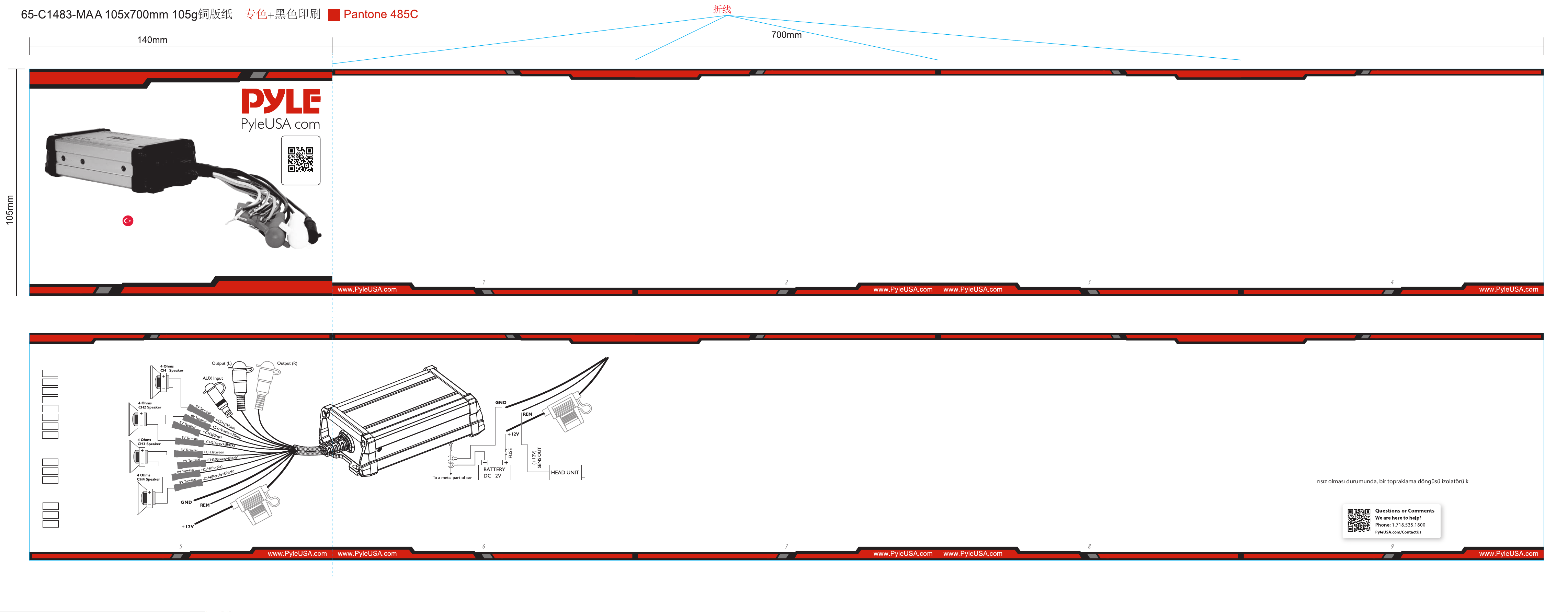
Bu güç amplikatörü, minimum bakımla yüksek kaliteli performans sağlamak üzere tasarlanmıştır.
Bununla birlikte, performansı yalnızca birlikte kurulduğu bileşenlerin bakımı ve kalitesi kadar iyi olacaktır.
Bu nedenle, ürünü ve özelliklerini tanımak için bu talimatları çok dikkatli bir şekilde okumanızı tavsiye ederiz.
Güç amplikatörünü kurmadan önce lütfen bu kullanım kılavuzunu dikkatlice okuyun. Setin montajı ve
bağlantısı için talimatlar tam olarak takip edilmelidir. Gerekirse bir servis merkezine danışılmalıdır. DC güç,
sinyal girişi ve hoparlör çıkışları için tüm bağlantılar RCA ve vidalı terminaller aracılığıyla kolayca ve güvenli bir
şekilde gerçekleştirilebilir.
Lütfen doğrudan hava etkilerinin olmadığı bir montaj yeri seçin. Amplikatörün ısı ürettiğini ve bu nedenle iyi
havalandırılan bir yerin gerekli olduğunu unutmayın. Aracınızın ve teknenizin yapısına göre, amplikatörün tam
performansını ve güvenilirliğini sağlamak için set çok dikkatli bir şekilde yapılabilir.
Güç kayıplarını en aza indirmek ve sistemden daha yüksek ses çıkışı sağlamak için kablo bağlantılarını yeterli
boyutlarda mümkün olduğunca kısa tutun. Güvenlik nedeniyle tüm güç ve hoparlör kablolarını çıkış kablo
kanallarını kullanarak yönlendirin. Kabloların hasar görmesini en aza indirmek için, keskin kenarlı metallerden
geçmemelerine dikkat edin. Tüm kabloları ateşleme kablolarından, bagajdaki modüllerden ve anahtar gösterge
panelinin altından mümkün olduğunca uzağa döşeyin, çünkü bunlar parazit oluşturur. (+) güç kablosuna,
pozitif akü kutbundan 30 cm'den fazla olmayan bir mesafede bir sigorta ekleyin. Güç kablolarının uzunluğunu
mümkün olduğunca kısa tutun. Kısa güç kabloları ve ardından daha uzun hoparlör kabloları kullanmak daha
iyidir. Paraziti azaltmak için talimatlara da dikkat edin.
• Bu ünite sadece negatif topraklı 12-14,50 Volt (DC) çalışma için tasarlanmıştır.
• Empedansı 4 Ohm olan hoparlörler kullanın
• Üniteyi aşağıdaki yerlere kurmaktan kaçının:
• Doğrudan güneş ışığı veya ısıtıcıdan gelen sıcak hava gibi yüksek sıcaklıklara maruz kalabilir.
• Yağmur veya neme maruz kalabileceği yerler.
• Toz veya kire maruz kalabilir.
GİRİŞ
KURULUM TALİMATLARI
Özellikler:
OPERASYON
ÖNLEMLER
KABLOLAMA TALİMATLARI
• Aracınız veya tekneniz doğrudan güneş ışığı alan bir yere park edilmişse ve içerideki sıcaklıkta önemli bir artış
varsa araba. çalıştırmadan önce ünitenin soğumasını bekleyin.
• Güvenlik nedeniyle, ses sisteminizin ses seviyesini makul bir mesafede normal trak seslerini duyabileceğiniz
şekilde orta düzeyde tutun.
• Optimum performansı normal bir akü besleme voltajına bağlı olduğundan, üniteyi zayıf bir otomatik akü ile
kullanmayın.
• Bu güç amplikatörü, amplikatörün arızalanması durumunda transistörleri ve hoparlörleri korumak için bir
koruma devresi kullanır. Soğutucuyu kapatarak veya uygun olmayan yükler bağlayarak koruma devrelerini
test etmeye çalışmayın.
• Bu ünite kaynak radyosuna çok yakın yerleştirilirse, bir parazit meydana gelebilir. Bu durumda, amplikatörü
araç radyosundan ayırın.
• Üniteyi yatay olarak kurarken, soğutucu uçlarını zemin halısı ile kapatmadığınızdan emin olun.
GÜÇ BAĞLANTISI
• Akü terminali (BATT), yeterli bir voltaj kaynağı sağlamak ve gürültüyü en aza indirmek için doğrudan araç
aküsünün pozitif terminaline bağlanmalıdır. akü terminali ucunun başka bir noktaya (sigorta bloğu gibi)
bağlanması güç çıkışını azaltacak ve gürültüye ve bozulmaya neden olabilecektir. Bu uç için sadece #12
ölçü’de veya daha kalın (daha küçük ölçü’de #) kablo kullanın ve diğer tüm kablo bağlantıları tamamlandıktan
sonra akünün terminaline bağlayın.
TOPRAK BAĞLANTISI
• Toprak terminali (GND) bağlantısı da amplikatörün doğru çalışması için kritik öneme sahiptir. Güç
bağlantısıyla aynı ölçülerde (#8 veya daha kalın) bir kablo kullanın ve bunu amplikatörün toprak terminali
(GND) ile aracın montaj yerine yakın metal bir parçası arasına bağlayın. Bu kablo mümkün olduğunca kısa
olmalı ve topraklama noktasındaki herhangi bir boya veya pas, topraklama kablosunun ucunun
vidalanabileceği veya cıvatalanabileceği temiz bir metal yüzey sağlamak için kazınmalıdır.
UZAKTAN AÇMA BAĞLANTISI
• Amplikatör, uzaktan açma terminaline (REM) + 12 uygulanarak açılır. Bu terminale giden kablo ucu, sadece
stereo kaynakları açıldığında +12 sağlayacak olan araç ve/veya tekne stereo kaynaklarından gelen "Otomatik
Anten" kablosuna bağlanmalıdır. Eğer araç stereo sistemi bir "Otomatik Anten" kablosu, uzaktan açma kablosu
aracın ve/veya teknenin sigorta bloğundaki bir "Aksesuar" veya "Radyo" terminaline bağlanabilir. Bu, stereo
kaynaklarının açık veya kapalı olmasına bakılmaksızın, kontak anahtarı ile amplikatörü açacak ve kapatacaktır.
Uzaktan açma kablosu büyük akımlar taşımaz. Bu yüzden bu uygulama için #16 ölçüsünde kablo kullanılabilir.
HOPARLÖR BAĞLANTILARI
• Amplikatörle birlikte kullanılan hoparlörlerin türüne ve sayısına bağlı olarak, bunları uygun kablolama
şemasına göre hoparlör terminallerine bağlayın. Çoğu uygulamada hoparlör uçları için # 18 ölçülü tel
kullanılmalıdır, ancak hiçbir durumda # 16 ölçü'den daha ince olmamalıdır. Uçlar için 10 feet'ten fazla #12 ölçü
önerilir. Hoparlörleri bağlarken, hoparlörlerdeki terminallerin polaritesine dikkat edin ve amplikatördeki ilgili
terminallerin polaritesine karşılık geldiklerinden emin olun. Hiçbir hoparlör kablosunu aracın/teknenin şasisine
topraklamayın.
GND (-) = TOPRAK BAĞLANTISI
• GND terminalini aracınızın/teknenizin şasi topraklamasına bağlayın ve en iyi elektrik ve mekanik temasa
dikkat edin. Bunu yaparken, amplinin yakınındaki araç / tekne şasisine bir delik açın ve ardından topraklama
noktasından renk, kir veya başka herhangi bir maddeyi temizleyin. Daha sonra kablo ucunu bir vida kullanarak
eklenen halka terminal ile sabitleyin. Topraklama bağlantısının mümkün olduğunca kısa olduğundan ve kablo
çapının yeterli olduğundan emin olun (min. 4 mm.). Telsizden ve ekolayzır, aktif crossover nerwork veya diğer
amplikatörler gibi diğer tüm ekipman parçalarından gelen topraklama kablolarını aynı topraklama noktasına
yönlendirin.
+ 12V = GÜÇ KAYNAĞI
• BATT terminalini bir kurşun kablo ile akünün artı kutbuna bağlayın ve aküden en fazla 30 cm uzakta olacak
şekilde güç kablosuna bir sigorta ekleyin. Kablo çapı 3 m uzunluk için en az 4 mm ve 6 m uzunluk için en az 6
mm olmalıdır.
REM (AÇMA/KAPAMA) UZAKTAN KUMANDA
• REM terminalini aracınızın ve/veya tekne radyonuzun otomatik anten konektörüne bağlayın. Artık aracınızın
ve/veya teknenizin radyosunu açıp kapatırken amplikatör otomatik olarak AÇIK ve KAPALI konuma geçer.
Kablo çapının 0,5 mm~ olması yeterlidir.
• Pro Audio PowerSport Amplikatör
• 4 Kanallı Ses Am Sistemi
• Denizcilik Sınıfı Sağlam Yapı
• Su Geçirmezlik Dereceli ve Hava Koşullarına
Dayanıklı Konnektörler
• Entegre Güç Kablo Demeti
• Özel Kurulumlar ve Uygulamalar için Mükemmel
• Harici Cihazlardan Ses Bağlayabilme ve Aktarabilme
• Kablolu Mini 3,5 mm AUX Ses Girişi
• Hoparlör Kablolama Bağlantısı
• Pre-Amp RCA Çıkışı Herhangi Bir OEM'e /
• Fabrika Yapımı Üniversal
• Mono Blok/veya Tam Aralıklı Amplikatör
• Vuruntu Önleyici Açma
• Yumuşak Açma / Kapama
• Aşırı Yük ve Güç Koruma Devresi
• Su Araçları için kullanılır
& Taşınabilir Mobil Araç Ses Sistemleri
Teknik Özellikler:
• Güç Çıkışı: 1500 Watt MAKS
• MAKS Güç: 4 x 375 Watt @ 4 Ohm (4 x 190 Watt
• Deniz Sınıfı Su Geçirmezlik Derecesi: IP-65
• T.H.D: %0.1
• S/N Oranı: > 95 dB'den fazla
• Kanal Ayrımı: > 65 dB'den fazla
• Frekans Tepkisi: 10 - 40kHz
• Sigorta: 20A
• Güç: DC 12V
• Am Boyutları (U x G x Y):
5,90" × 3,62" × 1,97" inç
(14.9 x 9.19 x 5 cm)
• Satış Şekli:1
Amplikatör kurulduktan ve tüm bağlantılar dikkatli ve güvenli bir şekilde yapıldıktan sonra, amplikatörün
otomatik olarak açılması için radyoyu açın. Kısa bir açılma süresinden sonra amplikatör tam performansına
ulaşır. Şimdi radyonun ses kontrolünü kullanarak sesi yavaşça açın. Eğer ses yoksa ya da sadece bozuk bir
şekilde çalıyorsa, radyoyu hemen kapatın - amplikatör de otomatik olarak kapanacaktır - ve tüm bağlantıların
doğru yapılıp yapılmadığını kontrol edin.
4-Ch Su geçirmezlik dereceli amplifikatör
PLMTR4A
ATV, UTV, 4x4, Jeep için Deniz Sınıfı
PowerSpot Amp (1500 Watt)
KULLANIM KILAVUZU
GÜÇ BAĞLANTI UÇLARIHOPARLÖR BAĞLANTILARI
SİGORTA DEĞİŞTİRME
ARIZA DURUMUNDA NASIL ILERLENMELI
MÜDAHALE
GÜÇ KAYNAĞIYLA ILGILI NOTLAR:
• 12V güç giriş kablosunu yalnızca diğer tüm kablolar bağlandıktan sonra bağlayın
• Ünitenin topraklama kablosunu aracın/teknenin metal bir parçasına sıkıca bağladığınızdan emin olun.
• Bağlantı kaybı amplikatörün arızalanmasına neden olabilir.
• REM: Ünite bu terminale +12 Volt uygulanarak açılır. Bu terminal, yedek Güç Terminalleri gibi ağır akım
çekmez, bu nedenle daha ince bir bağlantı teli kabul edilebilir. Standart 18 ölçülü uygundur ve standart rengi
kırmızıdır. Eğer radyo bir Güç Anteni kontrol kablosu ile donatılmışsa, bu terminali kullanabilir. Güç Anteni
kablosu zaten kullanılıyorsa, yine de ona ekleyebilirsiniz. Bu yöntemle, ünite radyo ile birlikte otomatik olarak
AÇIK konuma gelecektir.
• Değeri orijinal sigorta ile aynı olan bir sigortanın takılı olduğu güç kaynağı kablosunu kullanın.
• Sigortayı güç kaynağı kablosuna araç aküsüne mümkün olduğunca yakın yerleştirin.
• Tam güç çalışması sırasında, sistemden Maksimum akım geçecektir. Bu nedenle, ünitenin +12 ve GND
terminallerine bağlanacak uçların sırasıyla 18-ölçü'dan (AWG.18) daha büyük olduğundan emin olun. Sadece
mono sinyal mevcutsa, bir "Y" adaptörü gereklidir.
Sigorta atarsa, güç bağlantısını kontrol edin ve sigortayı değiştirin. Değiştirdikten sonra sigorta tekrar atarsa,
dahili bir arıza olabilir. Bu durumda satıcınıza danışın.
• ünite aşırı ısındığında.
• hoparlör terminalleri kısa devre yaptığında.
UYARI:
Belirtilen amperajlı sigortayı kullanın. Daha yüksek amperli bir sigortanın kullanılması ciddi hasara neden olabilir.
İşlev Yok:
• Bağlantı kablosu doğru bağlanmamış (=terminal + 12V/GND/REM).
Tüm bağlantıların ve mekanik temasın sağlandığından ve kılıfın çıkarıldığından emin olun.
Sigorta arızalı - yeni bir sigortanın doğru değerine dikkat edin!
KORUMA DEVRESİ:
Bu amplikatör, aşağıdaki durumlarda çalışan bir koruma devresi ile donatılmıştır:
• Hoparlör kablosunun artı ve eksi telleri temas eder, böylece kısa devreyi ortadan kaldırır.
Eğer kullanıyorsanız Dikkat edin sadece 4 ohm yük hoparlörüne izin verilir.
2 ohm veya daha düşük empedanslı hoparlör bağlantısına izin verilmez.
Ses Yok:
• Hoparlör kablosu veya hoparlör şi doğru bağlanmamış.
Kötü Ses Kalitesi (Bozulmalar):
• Hoparlörler aşırı yüklenmiştir, bu nedenle ses seviyesini düşürün ve ses kontrol konumlarını kontrol edin.
Stereo Ses Yok ve Zayıf Bas:
• Hoparlör kabloları (+) ve (-) karışmış, ünite faz dışı bağlanmış.
Tüm kablolar parazit kaynağı olabilir ve parazit oluşturabilir. Güç kablosu ve Cinch/RCA ses kablosu parazite
çok yatkındır; uzak kablolar daha az yatkındır. Genellikle jeneratör (boru tesisatı), ateşleme (çatlama) veya
diğer araç/tekne elektronik parçalarından kaynaklanan parazitler vardır. Bu sorunların çoğu doğru ve
dikkatli kablolama ile ortadan kaldırılabilir. Bunu yaparken, aşağıdaki yönergeleri dikkate alın:
• Amplikatörün "düşük seviye girişi" ile radyonun RCA veya DIN çıkışı arasındaki kablolama için yalnızca ekranlı
bir ses kablosu kullanın.
• Tüm bu önlemlerin başarısız olması durumunda, bir topraklama döngüsü izolatörü kullanılması sorunu
çözebilir.
• Temas direncini ve kötü ve gevşek temasları azaltmak için, lütfen kablo uçlarını lehimleyin veya çok damarlı
kablo uçları, kürek terminalleri veya diğerlerini kullanın. Altın Kaplama maça terminalleri korozyona uğramaz
ve en düşük temas direncine sahiptir.
• Uğultu sesleri varsa, daha kalın topraklama kabloları kullanın veya şasiye daha fazla topraklama kablosu
ekleyin.
• Araç elektriğinden sesler geliyorsa, güç kablolarına bir parazit bastırma bobini ekleyin.
• Hoparlör kablolarında harici elektrik kaynaklarından gelen manyetikler varsa, çekirdek uçlarını ayırın ve
birlikte bükün.
• Tüm bileşenlerin topraklama kablolarını yıldız benzeri bir şekilde bir merkez noktaya döşeyerek toprak
döngülerinden kaçının. En iyi merkezi noktayı doğrudan aküdeki voltajı ölçerek bulabilirsiniz. Şimdi bu voltaj
değerini seçilen toprak noktası ve amplikatörün (+) terminali ile karşılaştırın. Eğer ölçülen voltaj çok az
farklıysa, doğru merkezi bulmuşsunuz demektir. Aksi takdirde başka bir nokta aramanız gerekir. Topraklama
için kontak noktası açıkken ve ek olarak tüketiciler (arka cam ısıtması ve ışığı) açıkken ölçüm yapmalısınız.
• Sinyal, hoparlör ve güç kablolarını birbirlerinden ve ayrıca her bir araç kablosundan yeterince uzakta olacak
şekilde ayrı ayrı döşeyin. Eğer mümkün değilse, devre ve toprak kablosunu seri kablolarla birlikte
döşeyebilirsiniz. Ses ve hoparlör kablosu bunlardan mümkün olduğunca uzakta olmalıdır. Radyonun
otomatik anten çıkışına giden REM kablosu sinyal kabloları ile birlikte döşenebilir.
Hoparlör çıkışı
Seviye Giriş/Çıktı
Güç
+CH1
Beyaz
+CH2
+CH3
-CH2
Gri
-CH1
Beyaz+Siyah
Gri+Siyah
Yeşil
+CH4
Mor
-CH4
Mor+Siyah
IN Black(AUX)
OUT White (L)
OUT Kırmızı (R)
+ 12V Kırmızı
GND
Siyah
REM
Mavi
-CH3
Yeşil+Siyah
TUR
İnternet sitemizi
ziyaret edin
BENİ TARA
PyleUSA.com
