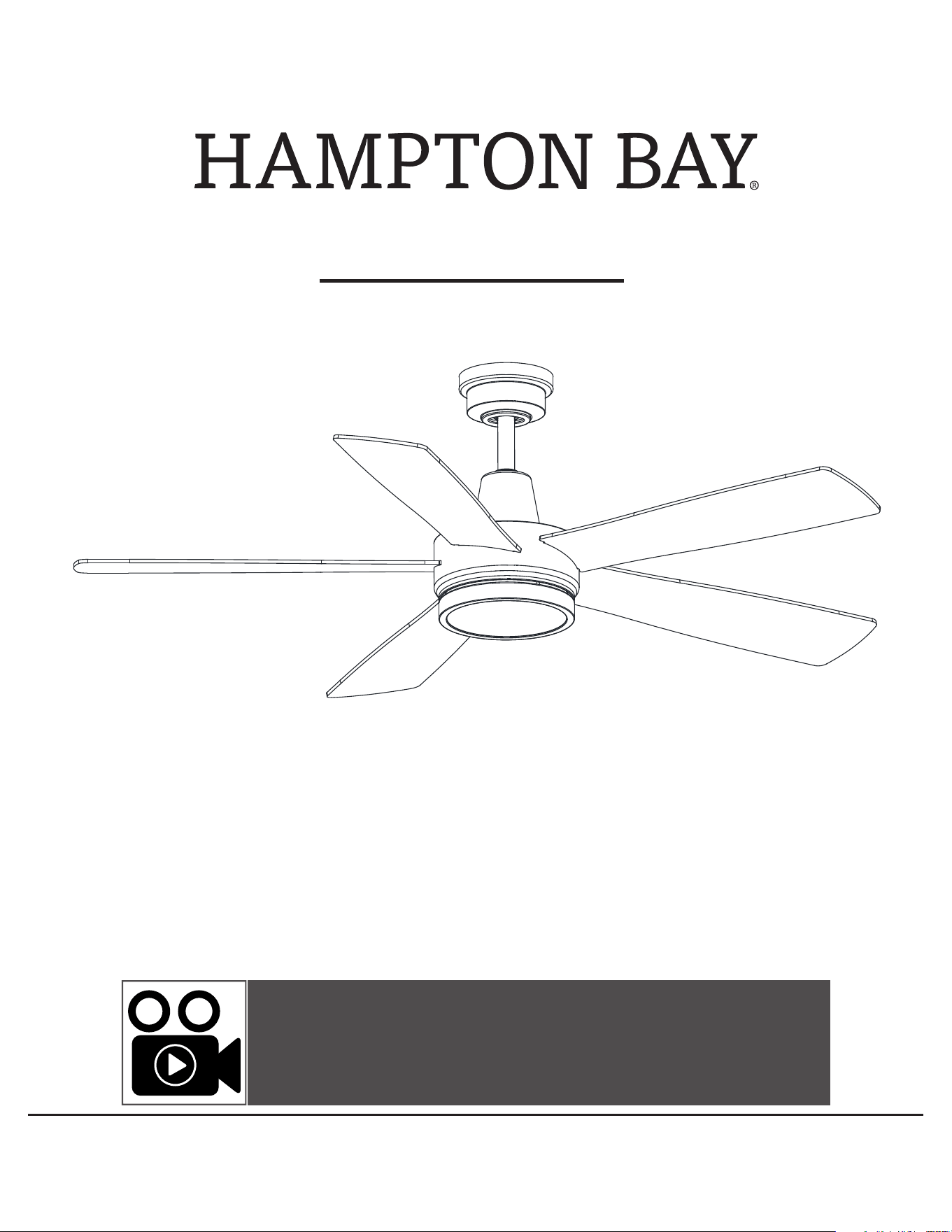
USE AND CARE GUIDE
FANELEE 54-INCH CEILING FAN
Item #1005 819 963
Model #52133
UL model #54-FANE
THANK YOU
We appreciate the trust and condence you have placed in Hampton Bay through the purchase of this ceiling fan. We strive to continually create
quality products designed to enhance your home. Visit us online to see our full line of products available for your home improvement needs.
Thank you for choosing Hampton Bay!
Questions, problems, missing parts? Before returning to the store,
call Hubspace Customer Service
8 a.m. - 7 p.m., EST, Monday-Friday, 9 a.m. - 6 p.m., EST, Saturday
1-877-592-5233
HOMEDEPOT.COM/HUBSPACE
To view an instructional video on how to install this product:
1. Go to www.homedepot.com and enter either the Item or Model number, found in the top
right corner of the cover of this instruction manual, in the search eld.
2. Click on your product from the list of search results and click on the video link in the
“Product Overview” section.
2
Table of Contents ................................................................2
Safety Information ...............................................................2
Warranty ............................................................................... 3
Pre-Installation ....................................................................3
Installation ............................................................................6
Assembly ..............................................................................7
Operation ...........................................................................13
Care and Cleaning ............................................................. 17
Troubleshooting ................................................................. 17
1. To reduce the risk of electric shock, ensure the electricity has been
turned off at the circuit breaker or fuse box before you begin.
2. All wiring must be in accordance with the National Electrical Code
ANSI/NFPA 70-1999 and local electrical codes. Electrical installation
should be performed by a qualified licensed electrician.
3. The outlet box and support structure must be securely mounted and
capable of reliably supporting 35 lbs (15.9 kg). Use only UL Listed outlet
boxes marked “Acceptable for Fan Support of 35 lbs (15.9 kg) or less.”
4. CAUTION: The fan must be mounted with a minimum of 7 ft. (2.1 m)
clearance from the trailing edge of the blades to the oor.
5. Do not operate the reversing switch while the fan blades are in
motion. You must turn the fan off and stop the blades before you
reverse the blade direction.
6. Do not place objects in the path of the blades.
7. To avoid personal injury or damage to the fan and other items, use
caution when working around or cleaning the fan.
8. Electrical diagrams are for reference only. Light kits that are not
packed with the fan must be UL-listed and marked suitable for use
with the model fan you are installing. Switches must be UL General
Use Switches. Refer to the instructions packaged with the light kits
and switches for proper assembly.
9. After making electrical connections, spliced conductors should be
turned upward and pushed carefully up into the outlet box. The
wires should be spread apart with the grounded conductor and the
equipment-grounding conductor on one side of the outlet box.
10. All setscrews must be checked and retightened where necessary
before installation.
WARNING: To reduce the risk of personal injury, do not
bend the blade brackets (also referred to as anges) during
assembly or after installation. Do not insert objects in the
path of the blades.
WARNING: To reduce the risk of re or electric shock, this
fan must be installed with an isolating wall switch.
WARNING: To avoid possible electrical shock, turn the
electricity off at the main fuse box before wiring. If you
feel you do not have enough electrical wiring knowledge or
experience, contact a licensed electrician.
WARNING: Electrical diagrams are for reference only.
Optional use of any light kit shall be UL-listed and marked
suitable for use with this fan.
WARNING: To reduce the risk of re, electric shock, or
personal injury, mount to outlet box marked “Acceptable
for fan support of 35 lbs. (15.9 kg) or less,” and use the
screws provided with the outlet box.
Safety Information
Table of Contents
READ AND SAVE THESE INSTRUCTIONS
WARNING: To reduce the risk of re or electric shock, this fan
should only be used with fan speed control part no. MR225A
manufactured by Chungear Industrial Co.,Ltd.
CAUTION: To reduce the risk of personal injury, use only the
screws provided with the outlet box.
This equipment has been tested and found to comply with the limits for a Class B digital device, pursuant to Part 15 of the FCC Rules. These limits are designed to provide reasonable
protection against harmful interference in a residential installation. This equipment generates, uses and can radiate radio frequency energy and, if not installed and used in accordance
with the instructions, may cause harmful interference to radio communications. However, there is no guarantee that interference will not occur in a particular installation. If this
equipment does cause harmful interference to radio or television reception, which can be determined by turning the equipment off and on, the user is encouraged to try to correct the
interference by one or more of the following measures:
□ Reorient or relocate the receiving antenna.
□ Increase the separation between the equipment and receiver.
□ Connect the equipment into an outlet on a circuit different from that to which the receiver is connected.
□ Consult the dealer or an experienced radio/TV technician for help.
Changes or modications not expressly approved by the party responsible for compliance could void your authority to operate the equipment. The distance between user and products
should be no less than 20 cm.
3
HOMEDEPOT.COM/HUBSPACE
Please contact 1-877-592-5233 for further assistance.
Pre-Installation
Warranty
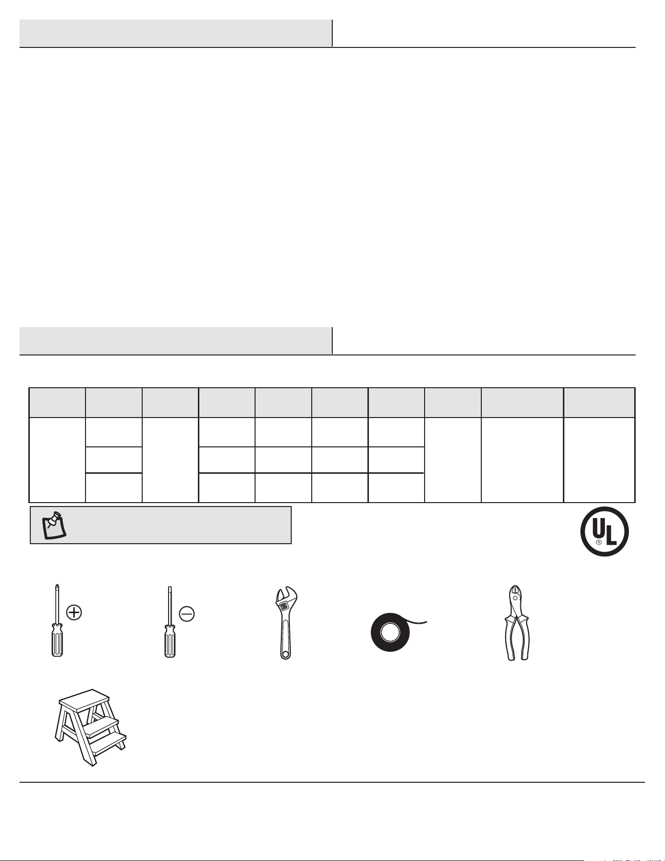
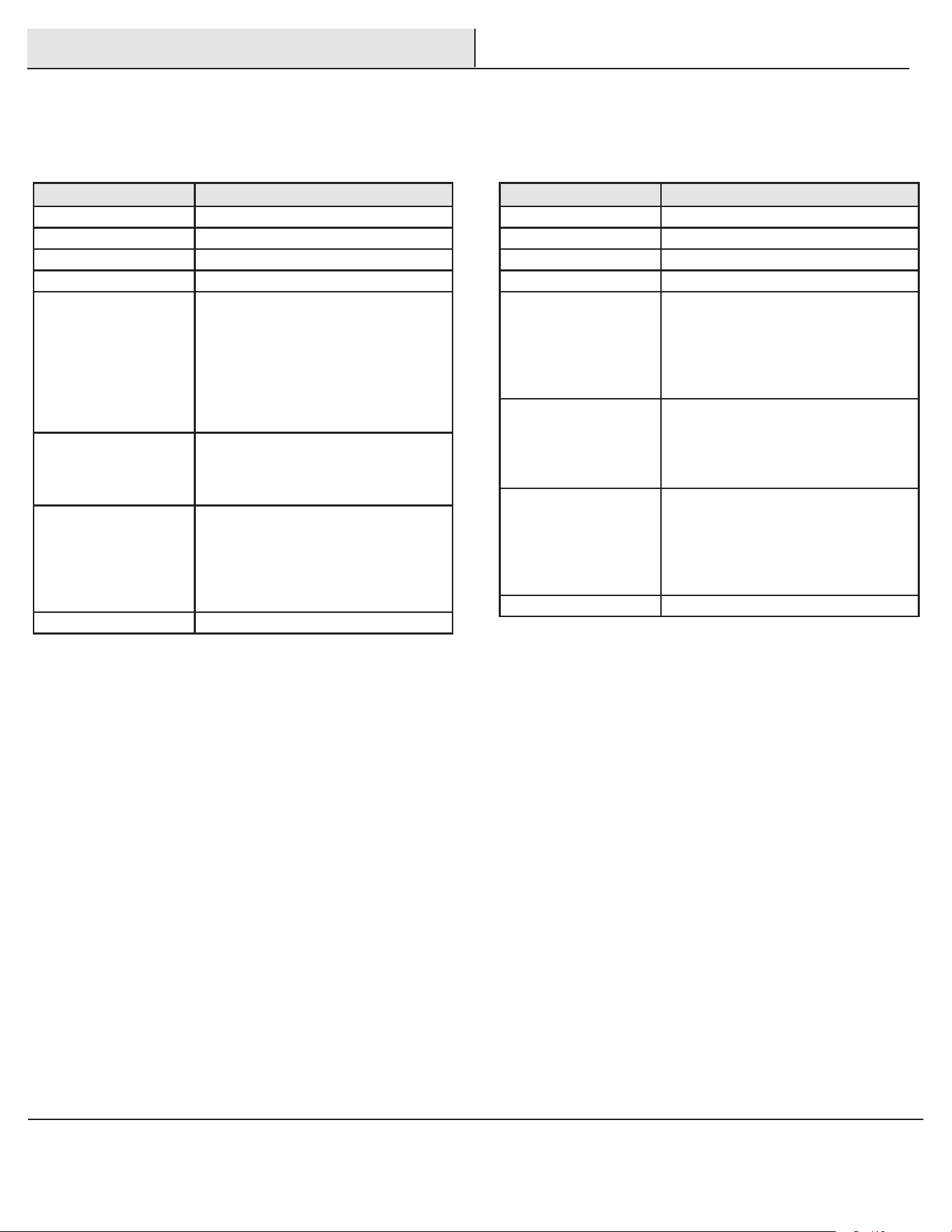
SPECIFICATIONS
TOOLS REQUIRED
Size Speed Volts Amps Watts RPM CFM
Net
Weight
Gross
Weight
Cubic Feet
54 in.
Low
Medium
High
120
0.20
0.37
0.52
8
29
63
50
100
160
2331
4186
6050
19.18 lbs
(8.7 kg)
23.37 lbs
(10.6 kg)
1.98 cu.ft.
NOTE: These are approximate measures. They do not
include the amps and wattage used by the light kit.
Phillips
screwdriver
Flat blade
screwdriver
Adjustable
wrench
Electrical
tape
Wire
cutter /
stripper
Step ladder
The supplier warrants the fan motor to be free from defects in workmanship and material present at time of shipment from the factory for a
lifetime after the date of purchase by the original purchaser. The supplier warrants that the light kit, excluding any glass, to be free from defects in
workmanship and material at the time of shipment from the factory for a period of three years after the date of purchase by the original purchaser.
The supplier also warrants that other fan parts, excluding any glass or acrylic blades, to be free from defects in workmanship and material at the
time of shipment from the factory for a period of one year after the date of purchase by the original purchaser. We agree to correct such defects
without charge or at our option replace with a comparable or superior model if the product is returned. To obtain warranty service, you must present
a copy of the receipt as proof of purchase. All costs of removing and reinstalling the product are your responsibility. Damage to any part, such as by
accident, misuse, improper installation, or by afxing any accessories, is not covered by this warranty. Because of varying climatic conditions this
warranty does not cover any changes in brass nish, including rusting, pitting, corroding, tarnishing, or peeling. Brass nishes of this type give their
longest useful life when protected from varying weather conditions. A certain amount of “wobble” is normal and should not be considered a defect.
Servicing performed by unauthorized persons shall render the warranty invalid. There is no other express warranty. Hampton Bay hereby disclaims
any and all warranties, including but not limited to those of merchantability and tness for a particular purpose to the extent permitted by law. The
duration of any implied warranty, which cannot be disclaimed, is limited to the time period as specied in the express warranty. Some states do not
allow a limitation on how long an implied warranty lasts, so the above limitation may not apply to you. The retailer shall not be liable for incidental,
consequential, or special damages arising out of or in connection with product use or performance except as may otherwise be accorded by law.
Some states do not allow the exclusion of incidental or consequential damages, so the above exclusion or limitation may not apply to you. This
warranty gives specic legal rights, and you may also have other rights that vary from state to state. This warranty supersedes all prior warranties.
Shipping costs for any return of product as part of a claim on the warranty must be paid by the customer.
Contact the Customer Service Team at 1-877-592-5233 or visit www.HomeDepot.com/hubspace.
4
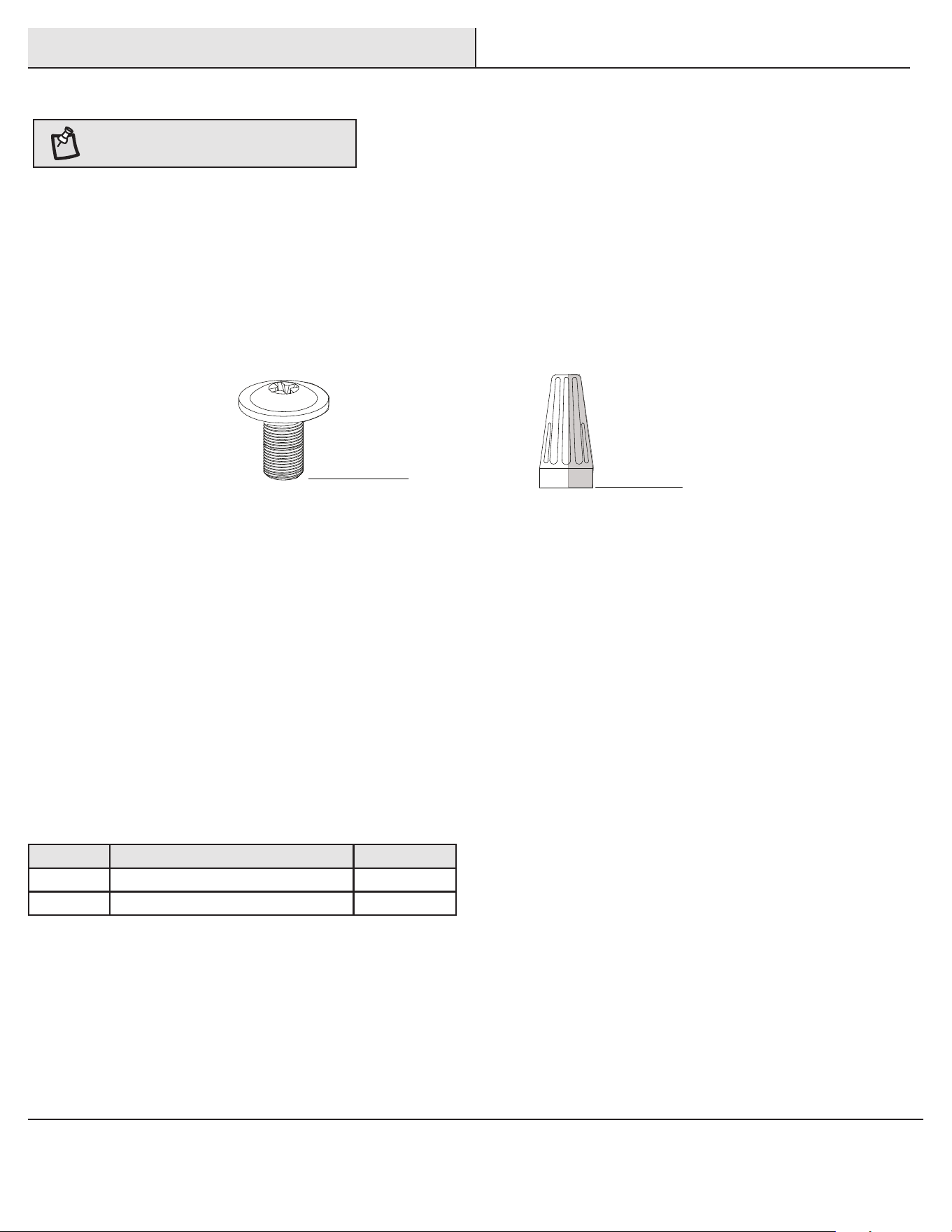
Part Description Quantity
AA Blade screws 16
BB Wire connecting nut 3
Pre-Installation (continued)
HARDWARE INCLUDED
NOTE: Hardware not shown to actual size.
BB
AA

5
HOMEDEPOT.COM/HUBSPACE
Please contact 1-877-592-5233 for further assistance.
Part Description Quantity
A Slide-on mounting bracket (inside canopy) 1
B Ball/downrod assembly 1
C Canopy 1
D Decorative motor collar cover 1
E Fan-motor assembly 1
Part Description Quantity
F Blade 5
G Decorative shade 1
H Receiver 1
I Remote control 1
J Lead wire 1
K Battery 2
IMPORTANT: This product and/or components are governed by
one or more of the following U.S. Patents: 5,947,436; 5,988,580;
6,010,110; 6,046,416, 6,210,117 and other patents pending.
Pre-Installation (continued)
PACKAGE CONTENTS
A
B
C
G
D
I
H
F
E
J
K
1
2 3
4
O
N
DIP
6
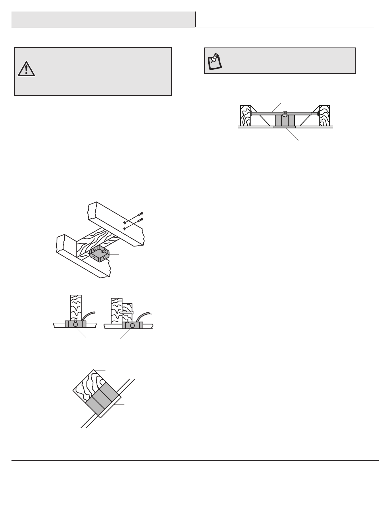
Installation
MOUNTING OPTIONS
WARNING: To reduce the risk of re, electric shock
or personal injury, mount to an outlet box marked
“Acceptable for fan support of 35 lbs. (15.9 kg) or less,”
and use the screws provided with the outlet box. An
outlet box commonly used for the support of lighting
xtures may not be acceptable for fan support and may
need to be replaced. If in doubt, consult a qualied
electrician.
If your ceiling fan does not have an existing UL mounting box,
then install one using the following instructions:
□ Disconnect the power by removing the fuses or turning off
the circuit breakers.
□ Secure the outlet box directly to the building structure.
Use the appropriate fasteners and materials. The outlet box
and its bracing must be able to fully support the weight
of the moving fan (at least 35 lbs.). Do not use a plastic
outlet box.
The illustrations below show three different ways to mount the
outlet box.
If the canopy (C) touches the ball/downrod assembly (B), then remove
the decorative canopy bottom cover and turn the canopy (C) 180°
before attaching the canopy (C) to the mounting plate.
To hang your fan where there is an existing xture but no ceiling joist,
you may need an installation hanger bar as shown above (available at
any Home Depot store).
NOTE: You may need a longer downrod to maintain
proper blade clearance when installing on a steep, sloped
ceiling. The maximum angle allowable is 20° away from
horizontal.
Outlet Box
Outlet Box
Recessed
Outlet
Box
Provide Strong
Support
Ceiling
Mounting
Plate
Outlet Box
Hanger Bar
7
HOMEDEPOT.COM/HUBSPACE
Please contact 1-877-592-5233 for further assistance.
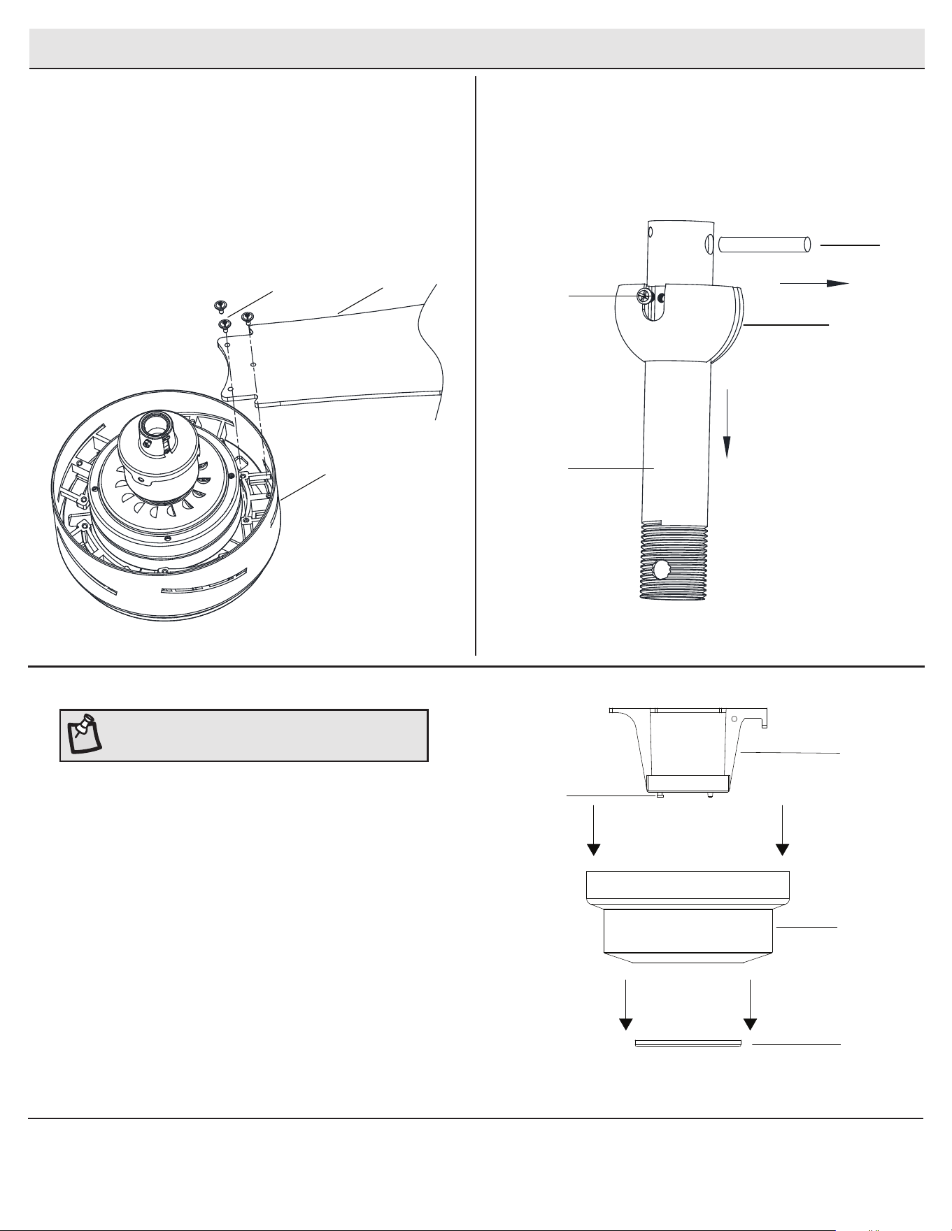
Assembly - Standard Ceiling Mount
Attaching the blades
□ Attach a blade (F) to the fan motor assembly (E) by inserting
the blade (F) into slots in the side of the fan motor assembly (E)
and aligning the three screws holes in the blade with the holes
in the center ywheel and secure with screws (AA).
□ Make sure all the screws are rmly tightened.
□ Repeat these steps for the remaining blades.
1
Removing the hanger ball
from the downrod
□ Remove the hanger ball from the downrod (B) by loosening
the set screw and removing the pin as shown in illustration.
Keep parts.
2
AA
F
E
Hanger ball
Set screw
Pin
B
Preparing for standard mounting
□ Pull off the canopy bottom cover (JJ) from the canopy (C).
□ Loosen the two canopy screws (HH) located on the bottom of the
mounting bracket (A), and turn the canopy counterclockwise
to remove the mounting bracket (A) from the canopy (C).
3
A
C
JJ
HH
NOTE: The magnet is pre-attached on the canopy bottom
cover for you to remove and install easily.
8
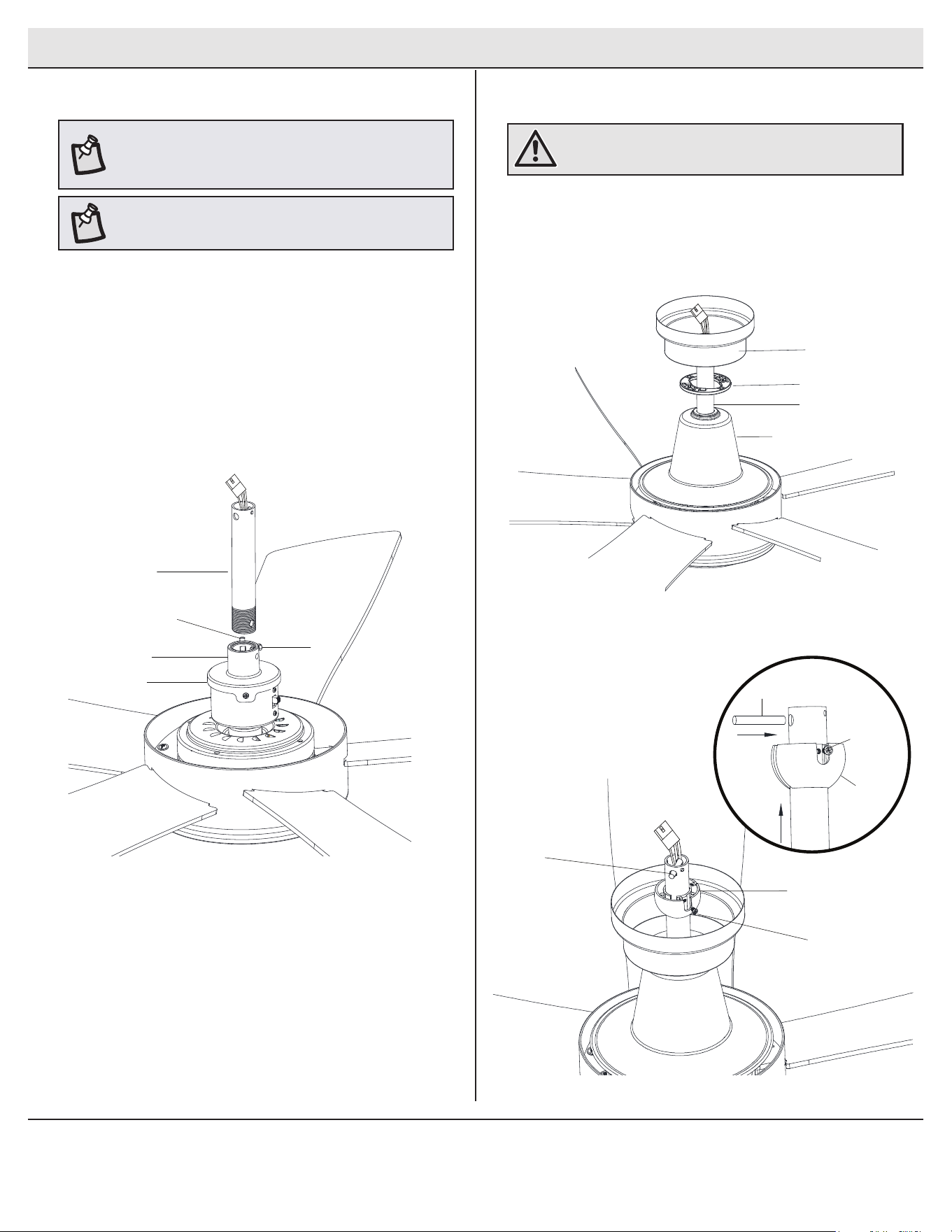
Assembly - Standard Ceiling Mount (continued)
Routing the wires
Assembling the fan
□ Place the decorative motor collar cover (D), canopy bottom cover
(JJ) and canopy (C) over lead wires and downrod.
□ Replace the hanger ball with pin and set screw. Tighten so the
setscrew is secure against the downrod (B).
□ Route the wires exiting the top of the fan motor assembly (E)
through the downrod (B).
□ Loosen, but do not remove, the setscrew (GG) on the motor collar
(PP) on top of the fan-motor assembly (E).
□ Install the downrod (B) by inserting it into the motor collar (PP)
and turning it clockwise until it is tight.
□ Re-tighten the setscrew (GG) on the motor collar (PP) so that the
setscrew (GG) is securely pressed against the downrod (B).
4
5
NOTE: This fan is equipped with a safety tab. Should the
setscrew (GG) ever become loose while the fan is running
in reverse, the safety tab will engage and stop the fan from
falling.
WARNING: Make sure the pin is installed well on hanger
ball with downrod.
PP
E
B
GG
Safety tab
NOTE: Place the fan on a soft surface, like a carpet or a towel,
to protect the LED module while attaching the downrod.
C
JJ
D
Hanger ball
Set screw
Pin
Hanger ball
Set screw
Pin
B
9
HOMEDEPOT.COM/HUBSPACE
Please contact 1-877-592-5233 for further assistance.
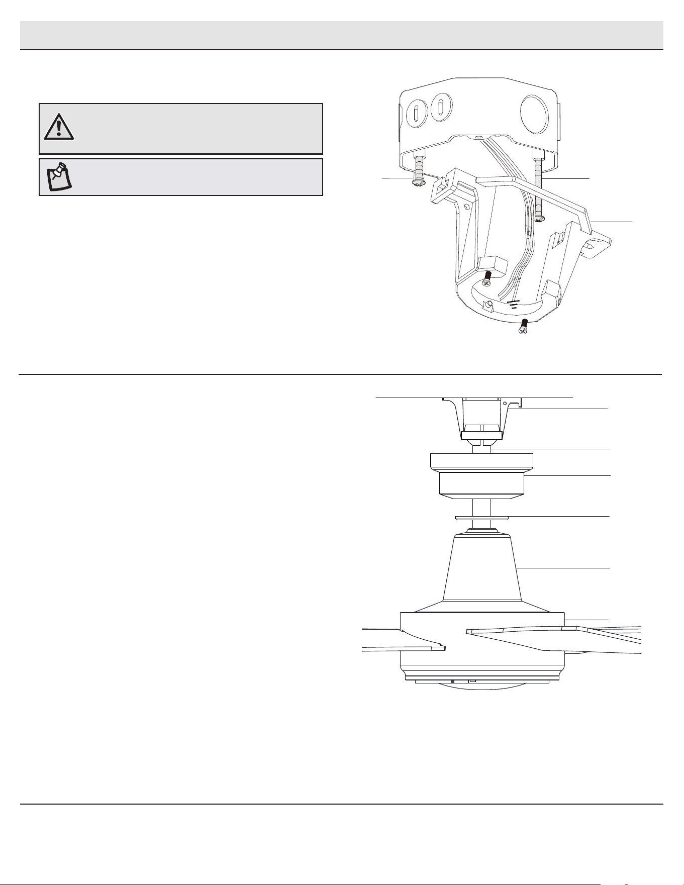
Assembly - Hanging the Fan
Attaching the fan to the
electrical box
□ Pass the 120-Volt supply wires through the center hole in the
slide-on mounting bracket (A).
□ Install the slide-on mounting bracket (A) on the outlet box by
sliding the slide-on mounting bracket (A) over the two screws
(MM) provided with the outlet box. If necessary, use leveling
washers (not included) between the slide-on mounting bracket
(A) and the outlet box. The at side of the slide-on mounting
bracket (A) should face toward the outlet box, as shown.
□ Securely tighten the two mounting screws (MM).
1
WARNING: To reduce the risk of re, electric shock or
personal injury, mount to an outlet box marked “Acceptable
for fan support of 35 lbs. (15.9 kg) or less,” and use the
screws provided with the outlet box.
Hanging the fan
2
□ Carefully lift the fan-motor assembly (E) up to the slide-on
mounting bracket (A).
□ Insert the ball portion of the ball/downrod assembly (B) into
the socket of the slide-on mounting bracket (A).
□ Turn the ball/downrod assembly clockwise until it is seated
with the tab of the slide-on mounting bracket (A) aligned with
the slot in the ball.
NOTE: The mounting bracket (A) is designed to slide into
place on an outlet box with the outlet box screws (MM).
A
MM
MM
A
B
C
D
JJ
E
10
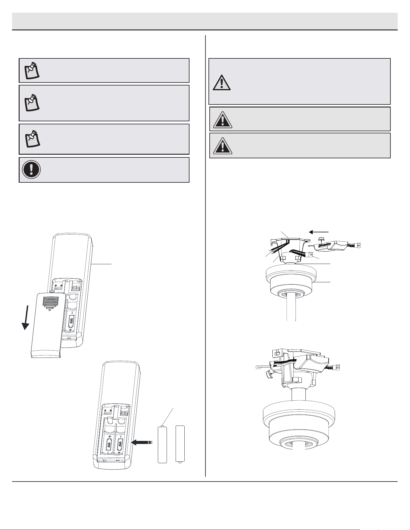
Assembly - Hanging the Fan (continued)
Installing the receiver
4
WARNING: To reduce the risk of re or electric shock, remember
to disconnect power. The electrical wiring must meet all local
and national electrical code requirements. The electrical source
and fan must be 110/120 volt, 60Hz. Do not use this product
in conjunction with any variable wall control. Incorrect wire
connection can damage this receiver.
□ Position the house supply wires (AAA) to one side of the slide-
on mounting bracket (A); position the fan wires (BBB) to the
opposite side.
□ Insert the narrow end of the receiver (H) (as shown, at side
towards the ceiling) into the slide-on mounting bracket until it
rests on top of the ball/downrod assembly.
Preparing the remote control
3
CAUTION: If other fan wires are a different color, have this
unit installed by a licensed electrician.
NOTE: The frequencies on your receiver and remote control
have been preset at the factory.
NOTE: The switch marked “D/O” controls the dimming
function of the lights. If you wish to use the dimming
functionality or Hubspace app, keep the switch in the “D”
position. To disable the dimming function, set the switch to
the “O” position.
NOTE: The battery will weaken with age and should be
replaced before leaking takes place, as battery leakage
damages the hand unit. Dispose of the used battery properly
and keep the battery out of the reach of children.
□ Remove the remote control (I) battery cover by pressing
rmly on the arrow and sliding the cover off.
□ Install two 1.5V batteries (included).
□ Replace the battery cover on the remote control (I).
CAUTION: Do not install in a damp location or immerse in
water (for indoor use only). Do not pull on or cut leads shorter.
Do not drop or bump the unit.
C
B
BBB
AAA
A
A
View after installation
IMPORTANT: If installing multiple remote control fans or to
re-pair the remote and receiver, please refer to “setting/
changing the remote frequency” on page 14.
I
K
11
HOMEDEPOT.COM/HUBSPACE
Please contact 1-877-592-5233 for further assistance.
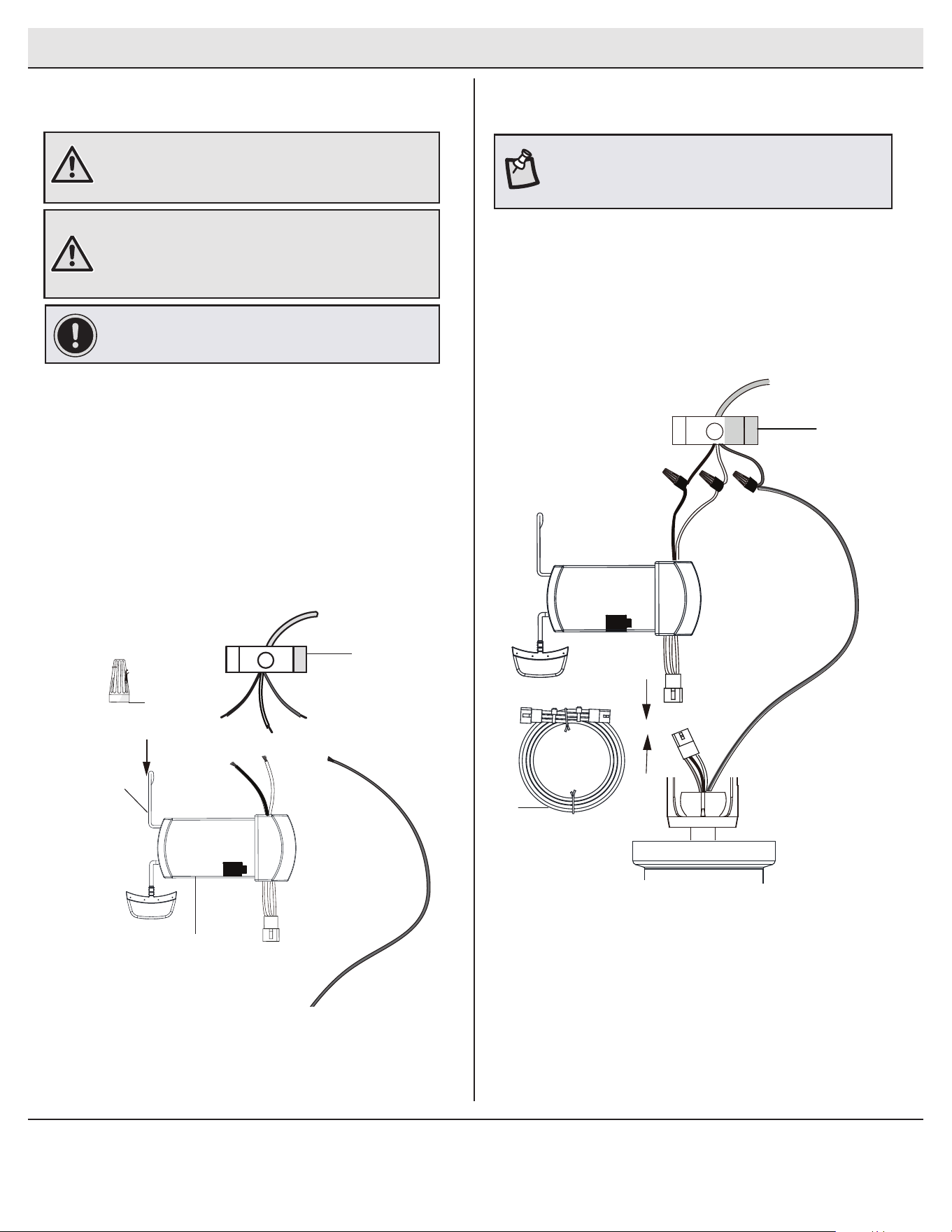
Assembly - Hanging the Fan (continued)
5
Wiring the receiver to the
household wiring
□ Spread the wires apart so that the green and white wires
are on one side of the outlet box and the black wire is on the
other side.
□ Connect the green fan wires to the household ground wire
(this may be a green or bare wire) using a wire connecting nut
(BB).
□ Connect the receiver (H) black or red wire to the household
black (hot) wire using a wire connecting nut (BB).
□ Connect the receiver (H) white wire to the household white
wire (neutral) using a wire connecting nut (BB).
□ Secure each wire connecting nut using electrical tape.
WARNING: To avoid possible electrical shock, turn the
electricity off at the main fuse box before wiring. If you
feel you do not have enough electrical wiring knowledge or
experience, contact a licensed electrician.
WARNING: Each wire nut supplied with this fan is designed
to accept up to one 12-gauge house wire and two wires
from the fan. If you have larger than 12-gauge house wiring
or more than one house wire to connect to the fan wiring,
consult an electrician for the proper size wire nuts to use.
IMPORTANT: Use the wire connecting nuts (BB) supplied
with your fan. Secure the connectors with electrical tape
and ensure there are no loose strands or connections.
6
Wiring the fan to the receiver
NOTE: The fan comes with 12 in. lead wires for use with
the provided 6 in. ball downrod assembly (B). If you wish
to use longer downrod, you can use the extension lead
wire (42 in.) (J) provided.
□ If using the 6 in. ball downrod assembly (B) provided, wire the
receiver to the fan wires by connecting the molded adaptor
plug from receiver (H) with molded adaptor of the fan motor
assembly (E) together.
□ If you wish to use longer downrod, you can use the extension
lead wire (42 in.) (J) provided by connecting the molded
adaptor together.
Outlet box
in the ceiling
(SS)
Green
1 2 3 4
ON
DIP
J
Black
Black
Green (or Bare)
Green
Outlet Box
Receiver
Antenna
White
Receiver (H)
BB (x3)
DIP
Antenna
WIFI
12
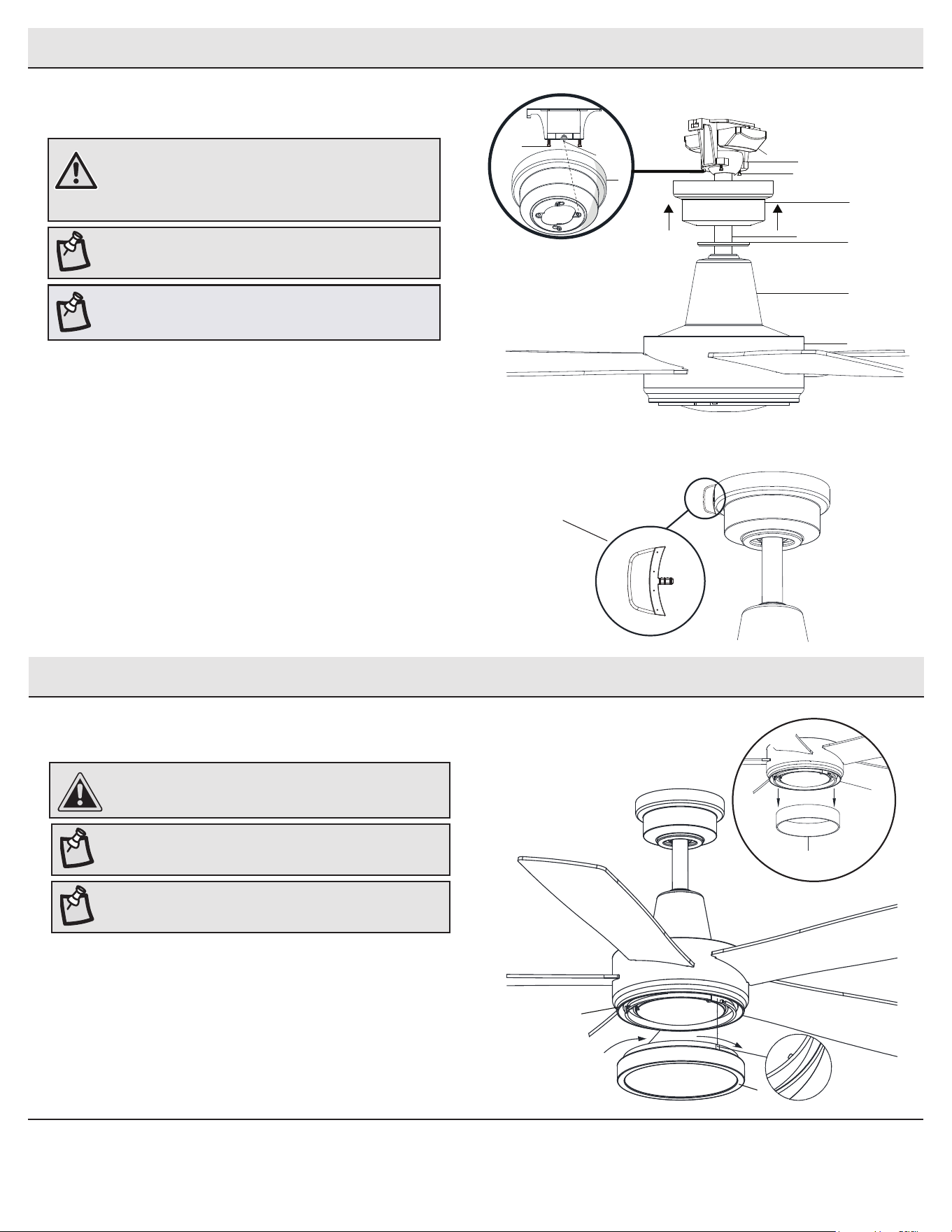
Mounting the fan-motor assembly
(standard mount)
7
□ Align the locking slots of the canopy (C) with the two
screws (HH) and alignment post (KK) in the mounting
bracket (A).
□ Push up the canopy (C) and turn clockwise until the
alignment post (KK) engage to the round hole and the
screws (HH) engage to the key slots.
□ Firmly tighten the two mounting screws (HH).
□ Align the oval shape on the canopy (C) with canopy bottom
cover (JJ). Push up the canopy bottom cover (JJ) until the
screw (HH) heads engage to the slots on the canopy bottom
cover (JJ) so that the magnetic canopy bottom cover (JJ)
can be attached to the bottom of the canopy (C) properly.
Assembly - Hanging the Fan (continued)
NOTE: The magnet is pre-attached on the canopy bottom
cover for you to remove and install easily.
WARNING: When using the standard ball/downrod
mounting, the tab in the ring at the bottom of the
mounting bracket must rest in the groove of the hanger
ball. Failure to properly seat the tab in the groove could
cause damage to the wiring.
Assembly - Attaching the Light
Attaching the decorative shade
1
□ Place the decorative shade (G) into the light kit pan, aligning the
three at areas on the top ange of the decorative shade (G) with
the raised dimples in the light kit pan.
□ Turn the decorative shade (G) clockwise until it stops.
CAUTION: To reduce the risk of electric shock, disconnect
the electrical supply circuit to the fan before installing the
light xture.
NOTE: Remove the cardboard insert from the motor housing
prior to hanging the fan.
KK
H
C
A
HH
B
C
D
JJ
E
WiFi antenna mount
outside of the canopy
View after installation
HH
NOTE: Remove the protective lm from the light kit lens
before attaching the decorative shade.
NOTE: For better performance with the WIFI system,
the WIFI antenna must be mounted to the ceiling
outside of the fan’s ceiling canopy.
G
Light kit pan
cardboard
13
HOMEDEPOT.COM/HUBSPACE
Please contact 1-877-592-5233 for further assistance.
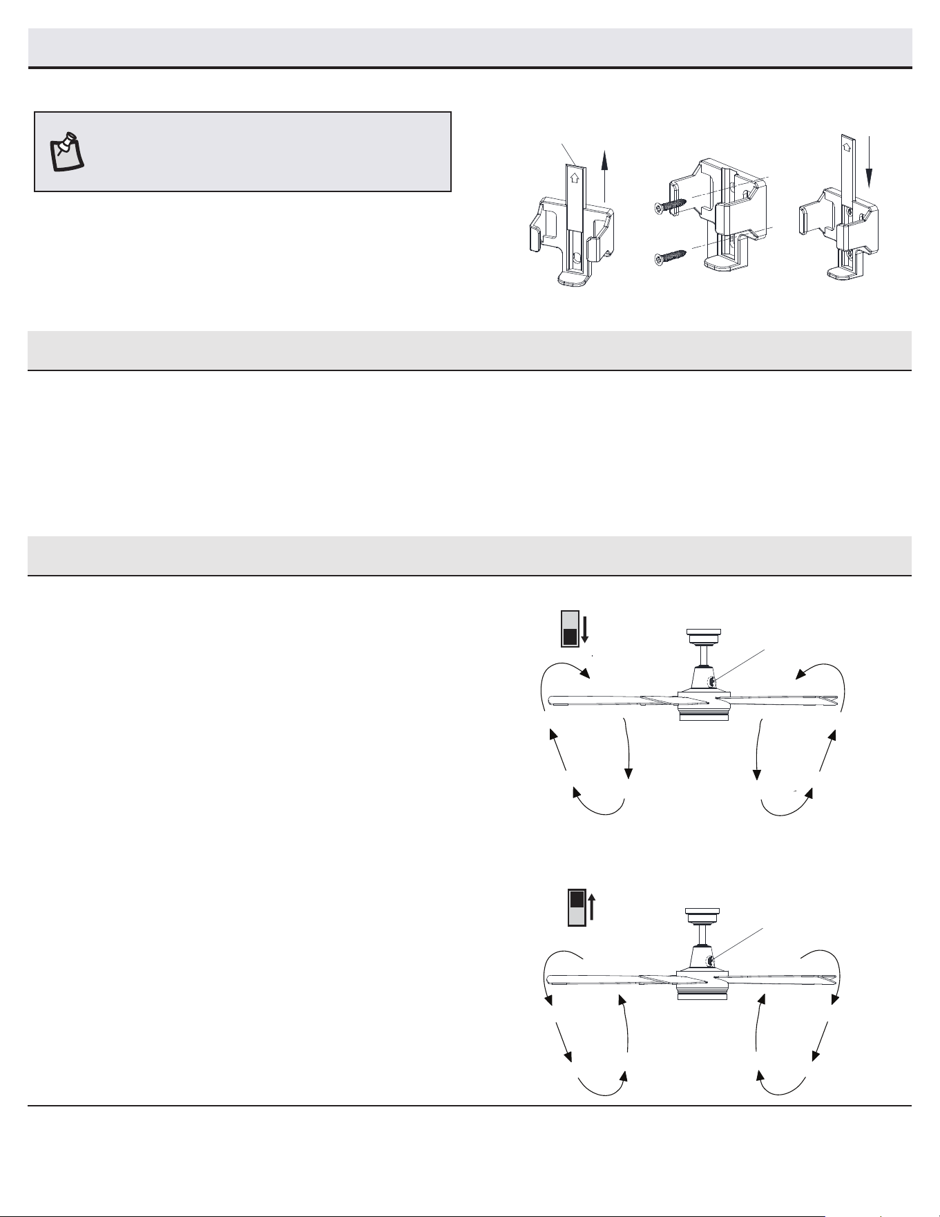
Assembly - Attaching the Accessories
Mounting the remote control holder
□ Slide the screw cover plate up to remove it from the wall
cradle.
□ Position the wall cradle in the desired position and attach it to
the wall using the included wall cradle screws.
□ Slide the screw cover plate back onto the wall cradle to
conceal the screws.
Sc
rew cover plate
NOTE: Screw wall anchors are included for extra support. The
included screws are designed to screw easily into the wall. If
you would like a more permanent or secure hold, install the wall
anchors prior to attaching the wall cradle to the wall.
Operating - Your Fan and Remote Control
Remote Control - Your fan is equipped with a remote control to operate
the speed and lights of your new ceiling fan.
Speed setting for warm or cool weather depends on factors such as
the room size, ceiling height, number of fans and so on.
The fan is shipped from the factory with the reversing switch (YY)
positioned to circulate air downward. If airow is desired in the
opposite direction, turn your fan off and wait for the blades to stop
turning, then slide the reversing switch (located underneath the motor
collar cover on the switch box on top of the motor housing) to the
opposite position, and turn the fan on again. The fan blades will turn in
the opposite direction and reverse airow.
Warm weather - (Forward) A downward airow creates a cooling effect.
This allows you to set your air conditioner on a higher setting without
affecting your comfort.
Cool weather - (Reverse) An upward airow moves warm air off of
the ceiling. This allows you to set your heating unit on a lower setting
without affecting your comfort.
A. Warm weather
B. Cool weather
YY
YY
Operating - Testing the Fan
□ Return power to the fan at the breaker box and wall switch (if applicable).
□ Press the fan speed button to test the fan.
□ Press the light button to test the light.
□ If the fan or light does not work, double check wiring connections and dip switch
settings in the remote and receiver.
14
Power ON/OFF: Press and release the power button to turn the fan and light on or off.
Fan speed: LEDs on the fan speed button will illuminate to the corresponding speed.
Press and release 1 time: turns the fan speed to 4.
Press and release 2 times: turns the fan speed to 3.
Press and release 3 times: turns the fan speed to 2.
Press and release 4 times: turns the fan speed to 1.
Press and release 5 times: turns the fan off.
Light ON/OFF:
Press and release the button to turn the light on or off.
Press and hold the button to activate the dimmer function.
Comfort Breeze: Press the button to enable Comfort Breeze; this will change your fan
randomly, simulating a relaxing breeze. To cancel this feature press fan speed button
or power button.
Correlated Color Temperature (CCT) changing: Push and release the button to cycle
through the six color temperature options.
Option 1: 2700K (Warm White).
Option 2: 3000K (Soft White).
Option 3: 3500K (Neutral White).
Option 4: 4000K (Bright White).
Option 5: 5000K (Daylight).
Option 6: 6500K (Daylight Deluxe).
Timer:
While the fan is on press 1 time-turns on a 2 hour run timer.
While the fan is on press 2 times-turns on a 4 hour run timer.
While the fan is on press 3 times-turns on a 8 hour run timer.
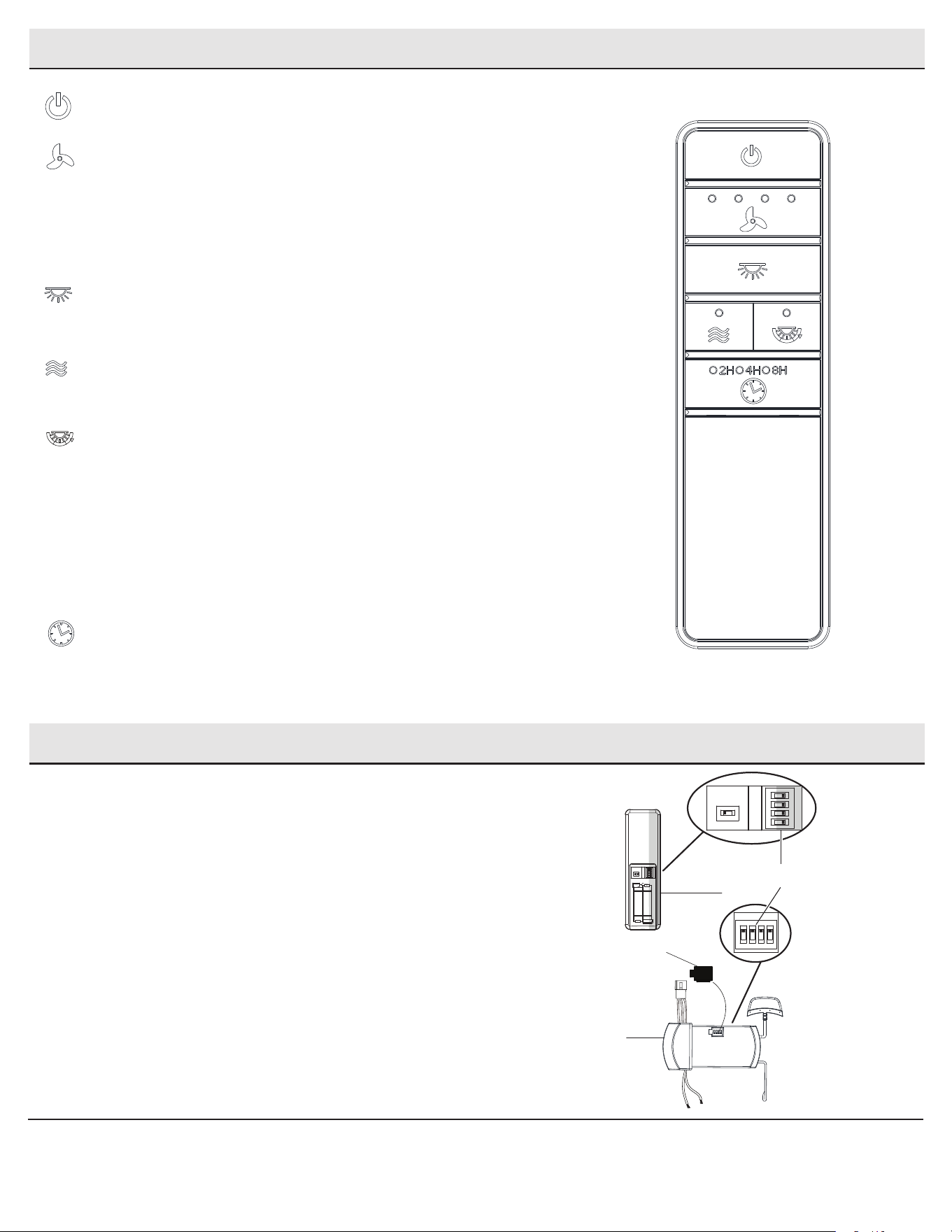
Operating - Your Fan and Remote Control (continued)
Setting/Changing the Remote Frequency
□ Remove the remote control (I) battery cover by pressing rmly
on the arrow and sliding the cover off.
□ Slide the dip switches (ZZ) in the battery compartment of the
remote control to your choice of either up or down. The factory
setting is up.
□ Remove the rubber plug (OO) from the receiver by pulling it out.
□ Slide the dip switches (ZZ) on the receiver (H) to the same
position as set on the remote control (I).
□ Replace the battery cover on the remote control (I).
□ Insert the silicone rubber stopper (OO) into the hole on the
receiver (H) to cover the dip switches.
I
H
ZZ
1 2 3 4
ON
D O
1
2
3
4
ON
D O
1 2 3 4
ON
OO
1 2 3 4
ON
DIP
15
HOMEDEPOT.COM/HUBSPACE
Please contact 1-877-592-5233 for further assistance.
Application Set-Up
□ Download the Hubspace™ app from the App Store or the Google Play Store to your mobile device.
□ Launch the app.
□ To register, enter your email address and a password. Or, login if you already have an account.
□ Bluetooth access is required for device setup.
Getting started
1
□ Hubspace only shows WiFi networks that your device can use. Check your network only if an option does not appear during set up.
□ This Hubspace device requires a 2.4GHz Wi-Fi channel.
□ Most routers provide a 2.4 GHz WiFi channel.
□ If you do not see your Wi-Fi network name when you attempt to connect your device, please check your router settings.
Verify your network
2
□ In the Hubspace app, tap the plus sign in the upper right corner.
□ Scan your product’s QR code. You can nd a copy of the QR code on the device itself and in the Quick Start Guide.
Scan problem?
If the QR code cannot be scanned for some reason, you can enter the code manually. Tap Enter Code and follow the instructions.
□ Connect your device to power and follow the instructions on screen.
(For lighting and fan products only)
Add a device
3
If you are unable to access the QR code for your light, you can put it into discovery mode with the following sequence:
□ Switch the device off and on 5 times. The light will pulse to show that it can now be discovered.
□ In the Hubspace app, tap the plus sign in the upper right corner and follow the instructions to discover devices. More than one device can be
added at a time using this method.
Set up your voice assistant
4
□ In the Hubspace app, tap the Hubspace button.
□ Select the Integrations tab, choose your voice assistant and follow the instructions.
Problems connecting to Hubspace device, see “troubleshooting” on page 16.
NOTE: For more information on smart remote set up, please refer
to the quick start guide located in the remote pack.
NOTE: To use Alexa to change the white temperature of the light,
please make sure the light is turned on rst.
Questions, problems missing parts?
Please call Hubspace Customer service
8 a.m. - 7 p.m. EST, Monday - Friday;
9 a.m. - 6 p.m., EST, Saturday
(877) 592-5233
16
Voice Commands
When you want to... Ask Alexa to...
Turn on the fan only. … turn on <device name> fan power.
Turn off the fan only. … turn off <device name> fan power.
Turn on the light only. … turn on <device name> light power.
Turn off the light only. … turn off <device name> light power.
Change the brightness. ... Set <device name> brightness to 75%.
… Set <device name> light to 25%.
… Make <device name> dimmer.
… Make <device name> brighter.
… Dim <device name>.
… Brighten <device name>.
… Dim <group name>.
… Brighten <group name>.
Change the White Temperature. … Change <device name> to Cool White.
… Change <device name> to Warm White.
… Change <device name> to Daylight White.
… Change <device name> to White.
Change the fan speed. … Set <device name> speed to fastest.
… Set <device name> speed to fast.
… Set <device name> speed to medium.
… Set <device name> speed to slow.
… Increase <device name> speed.
… Decrease <device name> speed.
Turn on Comfort Breeze. … Turn on Comfort Breeze on <device name>
Alexa
When you want to... Ask Google to...
Turn on the fan only. … turn on <device name> fan power.
Turn off the fan only. … turn off <device name> fan power.
Turn on the light only. … turn on <device name> light power.
Turn off the light only. … turn off <device name> light power.
Change the brightness. ... Set <device name> brightness to 75%.
… Set <device name> light to 25%.
… Brighten <device name>.
… Dim <device name>.
… Brighten <room name>.
… Dim <room name>.
Change the White Temperature. … Change <device name> to Ivory.
… Change <device name> to Daylight.
… Change <device name> to Cool White.
… Change <device name> to Warm White.
... Change <device name> to Incandescent.
Change the fan speed. … Set <device name> speed to fastest.
… Set <device name> speed to fast.
… Set <device name> speed to medium.
… Set <device name> speed to slow.
… Increase <device name> speed.
… Decrease <device name> speed.
Turn on Comfort Breeze. … Turn on Comfort Breeze on <device name>
Google
The Fanelee 54 in. LED Indoor Smart Color Changing Ceiling Fan works with Alexa and Google Assistant.
This section lists some of the voice commands you can use. To view these and other commands, go to http://hubspaceconnect.com/.
17
HOMEDEPOT.COM/HUBSPACE
Please contact 1-877-592-5233 for further assistance.
Troubleshooting
Problem Solution
The fan will not start. □ Check the main and branch circuit fuses or breakers.
□ Check to make sure the wall switch is in the on position if applicable.
□ Check the line wire connections to the fan and switch wire connections in the switch housing.
□ Check the battery in the transmitter.
□ Ensure you are in the normal range of 10-20 feet.
□ Ensure the dip switch settings are the same on the transmitter and receiver.
□ Remember to turn off the power supply before checking the dip switches settings.
The fan is noisy. □ Ensure all motor housing screws are snug.
□ Ensure the screws that attach the fan blade bracket to the motor hub are tight.
□ Ensure the wire nut connections are not rattling against each other or the interior wall of the switch housing.
□ Allow a 24-hour “breaking in” period. Most noises associated with a new fan disappear during this time.
□ If you are using the Ceiling Fan light kit, ensure the screws securing the glassware are tight. Check that the light bulbs are also secure.
□ Ensure the canopy is a short distance from the ceiling. It should not touch the ceiling.
□ Ensure your outlet box is secure and rubber isolator pads were used between the mounting plate and outlet box.
The fan wobbles. □ Check that all blade and blade arm screws are secure.
□ Most fan wobble problems are caused when blade levels are unequal. Check this level by selecting a point on the ceiling above the tip
of one of the blades. Measure from a point on the center of each blade to the point on the ceiling. Rotate the fan until the next blade is
positioned for measurement. Repeat for each blade. Any measurement deviation should be within 1/8”. Run the fan for ten minutes. If
the fan continues to wobble please contact customer service and a balancing kit will be sent to you at no charge.
Hubspace
TM
Troubleshooting
My hubspace device is not
connecting to Wi-Fi.
□ Make sure your device is connected to a power source.
□ Your Internet connection or Wi-Fi network may be down.
My device cannot nd any Wi-Fi
networks.
□ Make sure you have a 2.4GHz capable Wi-Fi network within range of the device you are trying to add.
My device is in a location that does
not have Wi-Fi. Can I still use it with
the Hubspace app?
Yes:
□ Use the app on a phone with an Internet connection like LTE.
□ The phone must be within Bluetooth range of your Hubspace device.
I cannot nd the QR code. □ Look for it where other stickers are on the product. A copy of the QR code is also included in your device’s documentation.
The QR code has become damaged.
How do I add the device?
□ Under the QR code are numbers. You can enter those in manually instead of scanning the code.
How do I reset the device? □ Remove the device from your account, then add it back. Devices also reset when they transfer to a new account.
A device is on another account.
How do I transfer it?
□ Scan the QR code and it will transfer to your account.
My device is ofine for long periods
of time.
□ Make sure your Wi-Fi signal strength is sufcient. You may need to move your router, use mesh Wi-Fi, or Wi-Fi extenders.
The device is on and I scanned
the QR code, but the app cannot
connect to it.
□ Turn off Bluetooth on your phone and turn it back on. Then, scan the QR code.
Can I scan the same QR code to add
multiple products?
□ No. Each product has a unique QR code.
□ Because of the fan’s natural movement, some connections may become loose. Check the support connections, brackets, and blade
attachments twice a year. Make sure they are secure. It is not necessary to remove the fan from the ceiling.
□ Clean your fan periodically to help maintain its new appearance over the years. Do not use water when cleaning, as this could damage
the motor or the wood, or possibly cause an electrical shock. Use only a soft brush or lint-free cloth to avoid scratching the nish. The
plating is sealed with a lacquer to minimize discoloration or tarnishing.
□ You can apply a light coat of furniture polish to the wood for additional protection and enhanced beauty. Cover small scratches with a
light application of shoe polish.
□ You do not need to oil your fan. The motor has permanently-lubricated sealed ball bearings.
WARNING: Make sure the power is off before cleaning
your fan.
Care and Cleaning

Questions, problems, missing parts? Before returning to the store,
call Hubspace Customer Service
8 a.m. - 7 p.m., EST, Monday-Friday, 9 a.m. - 6 p.m., EST, Saturday
1-877-592-5233
HOMEDEPOT.COM/HUBSPACE
Retain this manual for future use.