77886
Westinghouse Lighting, Philadelphia, PA 19154-1029, U.S.A. www.westinghouselighting.com
and Westingouse are trademarks of Westinghouse Electric Corporation. Used under license by Westinghouse Lighting. All Rights Reserved. Made in China
SAFETY PRECAUTIONS:
WARNINGS:
•
To avoid fire, shock, and serious personal injury, follow all
instructions carefully. all instructions carefully before installa-
tion. Save this Owner's Manual for future reference.
• Before servicing or cleaning the ceiling fan, switch power off
at service panel and lock service panel disconnecting means
to prevent power from being switched on accidentally. When
the service disconnecting means cannot be locked, securely
fasten a warning device such as a tag, to the service panel.
• WARNING: Do not install or use this unit if any part is dam-
aged or missing.
• Fans operated with this control must be suitable for use with
solid-state speed controls. Refer to the ceiling fan owner’s
manual to confirm if your fans are permitted to use sol-
id-state speed controls.
• WARNING: Use of this control with some ceiling fans could
result in fire, shock and serious personal injury. Use this
speed control only with Westinghouse 73191EC, 73123,
73135, 78003, 78127, 78614 and 78409 series ceiling fans
that are suitable for use with solid-state speed controls.
ADDITIONAL SAFETY INSTRUCTIONS FOR
INSTALLATION & NOTICE:
1.
To avoid possible electrical shock, be sure electricity is turned off at
the main fuse or circuit breaker box before wiring.
2.
Make certain no bare wires are exposed outside the wire connectors.
3. All wiring must conform to National and Local Electrical
Codes.
4.
This wall control is rated for Max. 8 Amps fan load at 120 volts.
5. All wiring must conform to National and Local Electrical
Codes. If you feel that you do not have enough electrical wir-
ing knowledge or experience, have your fan control installed
by a qualified electrician. Any electrical work not described in
this manual should be performed by a qualified electrician.
6
.
Use of this control with some ceiling fans could result in fire, shock,
and serious personal injury. Use this fan control only with capacitor
speed controlled ceiling fans only.
7.
The WHITE neutral wires inside the electrical box must be connected
together for proper operation of the wall control. NEVER connect the
WHITE neutral wires to the
Westinghouse
Jax Fan Wall Control.
8.
Warning! Do not connect any neutral (WHITE) wire to this control.
Incorrect wiring WILL damage this control.
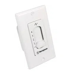
Installation & Operating Instructions for the
Westinghouse Jax fan Wall Control
WARNING: SHUT POWER OFF AT FUSE OR
CIRCUIT BREAKER
• 2-Wire • Infinitely Variable
• 8 Amps • Faceplate Included
MAKING THE ELECTRICAL CONNECTIONS
AND INSTALLATION:
NOTE: Installation of this control requires that the three-conductor
cable with ground wire be run between the control wall box and
the ceiling fan outlet.
1.
Improper wiring can damage the control and will void the war-
ranty.
2.
Disconnect power to the ceiling fan at the main electric panel.
Remove the fuse or switch the circuit breaker to the OFF position.
Warning! Turning off wall switch is not sufficient. To avoid
possible electrical shock, be sure electricity is turned off at
the main fuse or circuit breaker box before wiring. All wiring
must be in accordance with National and Local codes and
the ceiling fan must be properly grounded as a precaution
against possible electrical shock.
3. Carefully remove the rotary speeds knob and on/off switch
knob from the control (Refer to the diagram 1).
4. The front cover is installed by positioning the cover over the
ON/OFF button with the four protrusions inserted into the
groove provided on the extrusion ribs, gently push the cover
upwards so that the two protrusions on top of the cover are
higher than the extrusion ribs, take out the top half of the
cover and then push it downwards to make the other two
protrusions come out the extrusion ribs, take off the entire
cover. (Refer to diagram 2).
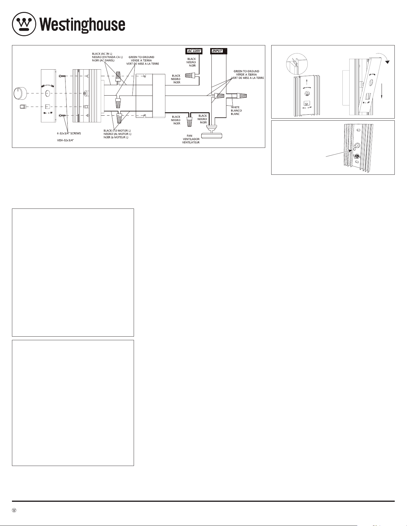
5. Follow wiring diagram 1 for wiring and installation of the wall
control to outlet box and use the screws supplied. Refer to
below detail for wiring.
NOTE: Refer to the diagram on the back of
the wall control.
• Connect the black wire marked with "TO MOTOR L" from the
wall control to the BLACK wire from the fan.
• Connect the black wire marked with "AC IN L" from the wall
control to the AC 120V HOT wire.
• Use the wire connectors provided to secure the connections.
• Connect the GREEN/Ground wire from wall control to the
ground wire from wall box.
• Secure the wall control to the wall box using the two #6-32”
x 3/4” screws provided.
Warning! Do not connect any neutral (WHITE) wire to this
control. Incorrect wiring WILL damage this control.
6. Reinstall the front cover, engage the two protrusions on
bottom of the cover into the groove provided on the extru-
sion ribs, gently push the cover upwards so that the two
protrusions on the front cover are higher than extrusion ribs,
press the cover towards the wall and push it downwards so
that the two protrusions on top of the cover are inserted into
the groove provided on the extrusion ribs. Install the ON/OFF
button, be sure the ON/OFF button is free to operate without
interference from the cover, install the rotary speed switch
button.
Warning! Check to see that all connections are tight, including
ground, and that no bare wire is visible at the wire connectors,
except for the ground wire.
7. With the wall control set to the off position, restore electricity
to the circuit from the circuit breaker panel or fuse box.
WARNING!
To reduce the risk of fire or electric shock or damage the fan
do not use this wall control together with any other additional
solid state fan speed control device, or variable speed control.
TROUBLESHOOTING GUIDE
PROBLEM: WALL CONTROL FAILS TO OPERATE
Check:
• Is there power to the control unit?
• Is the control unit wired correctly?
• Are the fan and light switches set on the highest position?
LIMITED WARRANTY
The Westinghouse universal Jax fan wall control offers a limited warranty
of one year from the date of purchase to the original owner against defects in
material and workmanship. All spare parts are covered for ninety days only.
This warranty is in lieu of all other warranties expressed or implied.
Westinghouse will repair or replace this universal Jax fan wall control if it
is defective due to faulty materials or workmanship. This warranty does not
cover service charges, defects resulting from accidents, damages caused
through abuse or alterations or by affixing any attachment not provided with
the product, improper installation or maintenance, failure of supporting devices
not supplied as original mounting hardware, exposures to extremes of heat or
humidity, incorrect voltage, surges in current, unauthorized repair, or failures
caused by modifications of the product or the acts of third parties. See remote
manual for proper installation.
If this product fails for any reason covered by this warranty, please con
-
tact us at www.westinghouselighting.com/contact-us.
77886
Diagram 1
Diagram 2
Diagram 3
LOW
HIGH
ON
OFF
HOW TO OPERATE YOUR WALL CONTROL:
1.
Turn the wall control “ON” using the push button on Westinghouse
Jax Fan Wall Control. Set the fan to “High” speed and allow the fan
to run for 30 minutes to normalize the motor temperature.
2.
It is recommended that the fans rotate at a minimum of 60 RPM
on low speed to avoid stalling the motor. To adjust the fan RPM,
locate the adjustment screw on the control’s front panel (Refer
to diagram 3). With a small flat blade screw driver, slowly turn
the adjustment screw clockwise to decrease RPM and count-
er-clockwise to increase RPM. Turn the adjustment screw in small
increments and allow the fan to speed up or slow down before
making the next adjustment.
3.
Turn the fan(s) off using the Westinghouse Jax Fan Wall Control ON/
OFF button.
4.
Turn the control knob to the High position and depress the ON/OFF
button and release. Adjust the fans speed to the desired comfort
level by rotating between the low and high positions. To turn the
fans off, depress ON/OFF button and release.
5. NOTE: Turning the speed control knob to high speed during start-
up will assist starting the fans and avoid stalling conditions.
6. The Westinghouse
Jax fan wall control is designed to operate
multiple fans without light kits.
The Westinghouse
Jax fan wall
control is rated for 8.0 amps 120V full load. It is recommended
the Westinghouse
Jax fan wall control shall have a minimum
load of 4.0 amps with fans at high speed. All ceiling fans must be
completely installed before installation of
the Westinghouse
Jax
wall control. Your new control will require a grounded electrical
supply line of 120 volts AC, 60 Hz, 15amp circuit.
Adjustment Screw
For use with 73191EC, 73123, 73135, 78003
78127, 78614 and 78409

77886
Westinghouse Lighting, Philadelphia, PA 19154-1029, U.S.A. www.westinghouselighting.com
and Westingouse are trademarks of Westinghouse Electric Corporation. Used under license by Westinghouse Lighting. All Rights Reserved. Made in China
PRECAUCIONES DE
SEGURIDAD:
ADVERTENCIAS:
•
Para evitar incendios, descargas eléctricas y lesiones graves,
siga todas las instrucciones cuidadosamente. Lea atentamente
todas las instrucciones antes de la instalación. Guarde este
manual del propietario para futuras consultas.
• Antes de reparar o limpiar el ventilador de techo, desconecte la
alimentación en el panel de servicio y bloquee los medios de
desconexión del panel de servicio para evitar un encendido acci
-
dental. Si los medios de desconexión del servicio no se pueden
bloquear, fije de forma segura un dispositivo de advertencia,
como una etiqueta, en el panel de servicio.
• ADVERTENCIA: No instale ni use esta unidad si falta alguna pieza
o si hay alguna pieza dañada.
• Los ventiladores operados con este control deben ser aptos para
usarse con controles de velocidad de estado sólido. Consulte el
manual del propietario del ventilador de techo para confirmar si
sus ventiladores pueden usarse con controles de velocidad de
estado sólido.
• ADVERTENCIA: El uso de este control con algunos ventiladores de
techo podría provocar incendios, descargas eléctricas y lesiones
graves. Use este control de velocidad únicamente con venti
-
ladores de techo de las series 73191EC, 73123, 73135, 78003,
78127, 78614 y 78409 de Westinghouse que sean aptos para
usarse con controles de velocidad de estado sólido.
INSTRUCCIONES DE SEGURIDAD ADICIONALES PARA
LA INSTALACIÓN Y AVISO:
1. Para evitar posibles descargas eléctricas, asegúrese de que el suministro
eléctrico esté desconectado en el fusible principal o en la caja de disyuntores
antes de realizar el cableado.
2. Asegúrese de que no haya conductores expuestos fuera de los conectores
de cables.
3. Todo el cableado debe cumplir con los códigos eléctricos nacionales y locales.
4. Este control de pared está clasificado para una carga máxima del ventilador de
8amperios a 120voltios.
5. Todo el cableado debe cumplir con los códigos eléctricos nacionales y locales.
Si cree que no posee suficientes conocimientos o experiencia en cableado
eléctrico, encargue la instalación del control del ventilador a un electricista
calificado. Cualquier trabajo eléctrico que no se describa en este manual debe
ser realizado por un electricista calificado.
6. El uso de este control con algunos ventiladores de techo podría provocar incen
-
dios, descargas eléctricas y lesiones graves. Use este control de ventilador úni-
camente con ventiladores de techo con control de velocidad por condensador.
7. Los conductores neutros BLANCOS que hay dentro de la caja eléctrica deben
conectarse entre sí para que el control de pared funcione correctamente. NO
conecte nunca los conductores neutros BLANCOS al control de pared para
ventilador Jax de Westinghouse.
8. ¡Advertencia! No conecte ningún conductor neutro (BLANCO) a este control. Un
cableado incorrecto dañaría este control.
Instrucciones de instalación y uso del control de
pared para ventilador Jax de Westinghouse
ADVERTENCIA: CORTE LA ALIMENTACIÓN
EN EL FUSIBLE O EN EL DISYUNTOR
• 2cables • infinitamente variable
• 8amperios • Placa frontal incluida
ESTABLECIMIENTO DE LAS CONEXIONES
ELÉCTRICAS E INSTALACIÓN:
NOTA: Para la instalación de este control, es necesario tender el cable de tres conduc-
tores con conductor de puesta a tierra entre la caja del control de pared y la salida del
ventilador de techo.
1. Un cableado incorrecto podría dañar el control y conllevaría la anulación
de la garantía.
2. Desconecte la alimentación del ventilador de techo en el panel eléctrico
principal. Retire el fusible o cambie el disyuntor a la posición APAGADO.
¡Advertencia! No basta con apagar el interruptor de pared. Para evi
-
tar posibles descargas eléctricas, asegúrese de que el suministro
eléctrico esté desconectado en el fusible principal o en la caja de
disyuntores antes de realizar el cableado. Todo el cableado debe
cumplir con los códigos nacionales y locales y el ventilador de techo
conectarse correctamente a tierra como precaución contra posibles
descargas eléctricas.
3. Retire con cuidado el botón giratorio de selección de velocidad y el
botón de encendido/apagado del control (véase el diagrama1).
4. Para instalar la cubierta frontal, coloque la cubierta sobre el botón de
encendido/apagado con las cuatro protuberancias insertadas en la
ranura provista en las nervaduras de extrusión, empuje suavemente
la cubierta hacia arriba hasta que las dos protuberancias que hay en
la parte superior de la cubierta queden más altas que las nervaduras
de extrusión, saque la mitad superior de la tapa y empújela hacia abajo
para que las otras dos protuberancias salgan por las nervaduras de
extrusión. Por último, saque toda la tapa (véase el diagrama2).
5. Utilice los tornillos suministrados de acuerdo con el diagrama de
cableado 1 para instalar el control de pared y conectarlo a la caja
de salida. A continuación se incluye información detallada sobre el
cableado. NOTA: Consulte el diagrama que hay en la parte posterior
del control de pared.
• Conecte el conductor negro marcado con «TO MOTOR L» del control de
pared al conductor NEGRO del ventilador.
• Conecte el conductor negro marcado con «AC IN L» del control de pared
al conductor de 120VCA.
• Utilice los conectores de cable provistos para asegurar las conexiones.
• Conecte el conductor VERDE/de puesta a tierra del control de pared al
conductor de puesta a tierra de la caja de pared.
• Asegure el control de pared a la caja de pared usando los dos tornillos
6-32” x 3/4” provistos.
¡Advertencia! No conecte ningún conductor neutro (BLANCO) a este
control. Un cableado incorrecto dañaría este control.
6. Vuelva a instalar la cubierta frontal, encaje las dos protuberancias
que hay en la parte inferior de la cubierta en la ranura provista en las
nervaduras de extrusión, empuje suavemente la cubierta hacia arriba
de modo que las dos protuberancias de la cubierta frontal queden
más altas que las nervaduras de extrusión, presione la cubierta hacia
la pared y empújela hacia abajo hasta que las dos protuberancias que
hay en la parte superior de la cubierta se inserten en la ranura provista
en las nervaduras de extrusión. Instale el botón de encendido/apagado,
asegúrese de que el botón de encendido/apagado pueda moverse libre
-
mente, sin que la cubierta interfiera con él, e instale el botón giratorio
de selección de velocidad.
¡Advertencia! Compruebe que todas las conexiones estén apretadas,
incluida la conexión de puesta a tierra, y que no se vea ningún conduct
expuesto en los conectores de cables, excepto el conductor de puesta
a tierra.
7. Con el control de pared en la posición de apagado, restablezca el sum
-
inistro eléctrico al circuito desde el panel de disyuntores o la caja de
fusibles.
¡ADVERTENCIA!
Para reducir el riesgo de incendio, de descarga eléctrica o de dañar el
ventilador, no use este control de pared junto con ningún otro disposi-
tivo de control de velocidad de ventilador de estado sólido o control de
velocidad variable.
GUÍA DE RESOLUCIÓN DE PROBLEMAS
PROBLEMA: EL CONTROL DE PARED NO FUNCIONA.
Comprobación:
• ¿Recibe la unidad de control suministro eléctrico?
• ¿Se ha cableado correctamente la unidad de control?
• ¿Están los interruptores del ventilador y de la luz en la posición más alta?
GARANTÍA LIMITADA
El control de pared para ventilador Jax universal de Westinghouse se suministra una
garantía limitada de un año a partir de la fecha de compra al propietario original contra
defectos de material y de mano de obra. Todas las piezas de repuesto están cubiertas
solo durante noventa días. Esta garantía reemplaza cualquier otra garantía expresa o
implícita.
Westinghouse reparará o reemplazará este control de pared para ventilador Jax uni-
versal si presenta algún defecto material o de mano de obra. Esta garantía no cubre cargos
por servicio, defectos resultantes de accidentes, daños causados por uso inadecuado, por
alteraciones o por el montaje de cualquier accesorio no incluido con el producto, instalación
o mantenimiento inadecuados, fallos de los dispositivos de soporte no suministrados
como accesorios de montaje originales, exposición a niveles extremos de calor o humedad,
voltaje incorrecto, picos de corriente, reparaciones no autorizadas o fallos causadas por
modificaciones del producto o actos de terceros. Consulte el manual del control remoto
para una instalación adecuada.
Si este producto falla por algún motivo cubierto por esta garantía, comuníquese con
nosotros en www.westinghouselighting.com/contact-us.
77886
Diagrama 1
Diagrama 2
Diagrama 3
LOW
HIGH
ON
OFF
MANEJO DEL CONTROL DE PARED:
1. Encienda el control de pared mediante el botón del control de pared
para ventilador Jax de Westinghouse. Ajuste el ventilador a velocidad
«Alta» y deje que funcione durante 30 minutos para normalizar la
temperatura del motor.
2. Se recomienda que los ventiladores giren a un mínimo de 60rev./min a
baja velocidad para evitar que el motor se atore. Para ajustar la veloci
-
dad del ventilador, localice el tornillo de ajuste que hay en el panel
frontal del control (vea el diagrama3). Con un destornillador pequeño
de punta plana, gire lentamente el tornillo de ajuste en el sentido de las
agujas del reloj para disminuir la velocidad y en el sentido contrario a
las agujas del reloj para aumentar la velocidad. Gire el tornillo de ajuste
en pequeños intervalos y deje que el ventilador aumente o disminuya
de velocidad antes de realizar el siguiente ajuste.
3. Apague el ventilador o los ventiladores con el botón de encendido/
apagado del control de pared para ventilador Jax de Westinghouse.
4. Gire el botón de control a la posición «Alta», pulse el botón de encendi
-
do/apagado y suéltelo. Ajuste la velocidad de los ventiladores al nivel
de comodidad deseado girando el botón entre las posiciones «Baja»
y «Alta». Para apagar los ventiladores, pulse el botón de encendido/
apagado y suéltelo.
5. NOTA: Girar el botón de control de velocidad a alta velocidad durante
el arranque ayudará a que los ventiladores se pongan en marcha y
evitará que se atoren.
6. El control de pared para ventilador Jax de Westinghouse se ha diseña
-
do para controlar varios ventiladores sin juegos de luces. El control de
pared para ventilador Jax de Westinghouse está clasificado para una
carga máxima de 8,0amperio a 120V. Se recomienda que el control
de pared para ventilador Jax de Westinghouse tenga una carga
mínima de 4,0amperio con ventiladores a alta velocidad. Todos los
ventiladores de techo deben estar completamente instalados antes
de instalar el control de pared Jax de Westinghouse. Su nuevo control
requerirá una línea de suministro eléctrico de 120amperioCA, 60 Hz,
15amperios con puesta a tierra.
Tornillo de ajuste
Para uso con 73191EC, 73123, 73135, 78003
78127, 78614 y 78409