
1
2
3
4
6
5
9
8
11
17
16
12
15
13
14
18
19
15 16
17
7
8
10
8
9
21
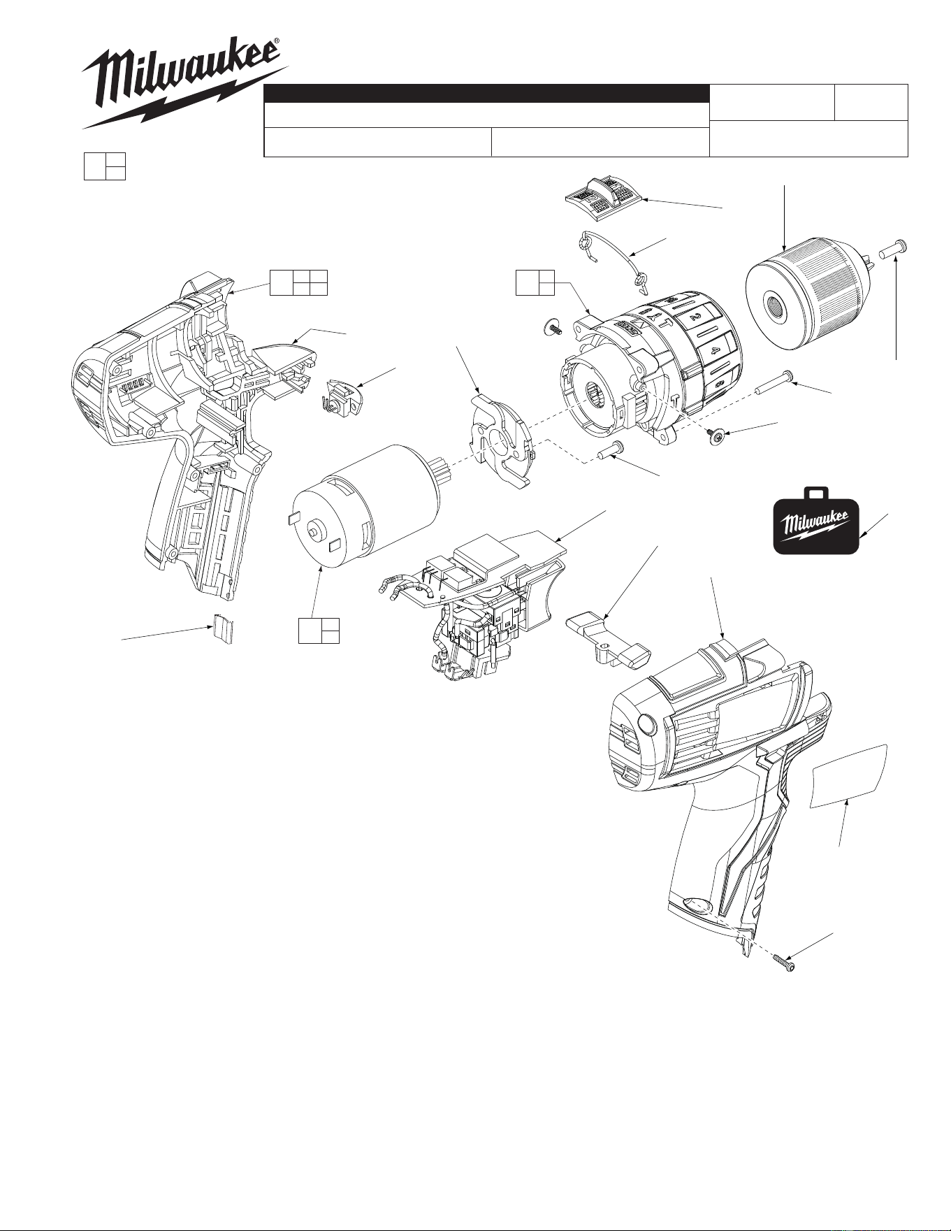
BULLETIN NO.
54-24-2410
SERVICE PARTS LIST
FIG. PART NO. DESCRIPTION OF PART NO. REQ.
1 05-88-1680 M5 x 13.5 LH Chuck Screw (1)
2 42-66-0530 3/8" Keyless Chuck (1)
3 45-24-0325 Speed Slide (1)
4 44-10-0720 Speed Selector Wire Link (1)
5 05-81-0535 M2.3 x 4.5 Philips Shift Lever Screw (2)
6 05-88-0780 M3 x 18 ST T-10 Gearcase Screw (4)
7 14-30-1080 Gearcase Assembly (1)
8 --------------- Motor Mounting Plate (1)
9 --------------- Motor Mounting Screw (2)
10 23-30-0830 Motor Assembly (1)
11 23-66-4000 Switch Assembly (1)
12 45-24-0275 Forward/Reverse Lever (1)
13 12-20-2411 Service Nameplate (1)
14 06-82-1080 M3 x 14 ST T-10 Housing Screw (5)
15 --------------- Right Housing (1)
16 --------------- Left Housing (1)
17 31-15-1575 LED Cover (1)
18 42-70-0055 Housing Clip (1)
19 31-44-2580 Housing Kit (1)
20 10-20-2885 Warning Label (Not Shown) (1)
21 42-55-2480 Carrying Case, Optional (1)
CATALOG NO. 2411-20
REVISED BULLETIN
SPECIFY CATALOG NO. AND SERIAL NO. WHEN ORDERING PARTS
Cordless 12 Volt 3/8" Hammer-Drill
STARTING
SERIAL NO.
WIRING INSTRUCTION
C72A
SEE REVERSE SIDE
DATE
Feb. 2011
MILWAUKEE ELECTRIC TOOL CORPORATION
13135 W. Lisbon Road, Brookfi eld, WI 53005
Drwg. 2
FIG. NOTES:
7, 8, 10 Service replacement gearcase assembly (7) comes with a
motor mount plate (8) that must be removed and discarded
when servicing. A motor mount plate already exists on the
motor assembly (10).
0
EXAMPLE:
Component Parts (Small #)
Are Included When Ordering
The Assembly (Large #).
00
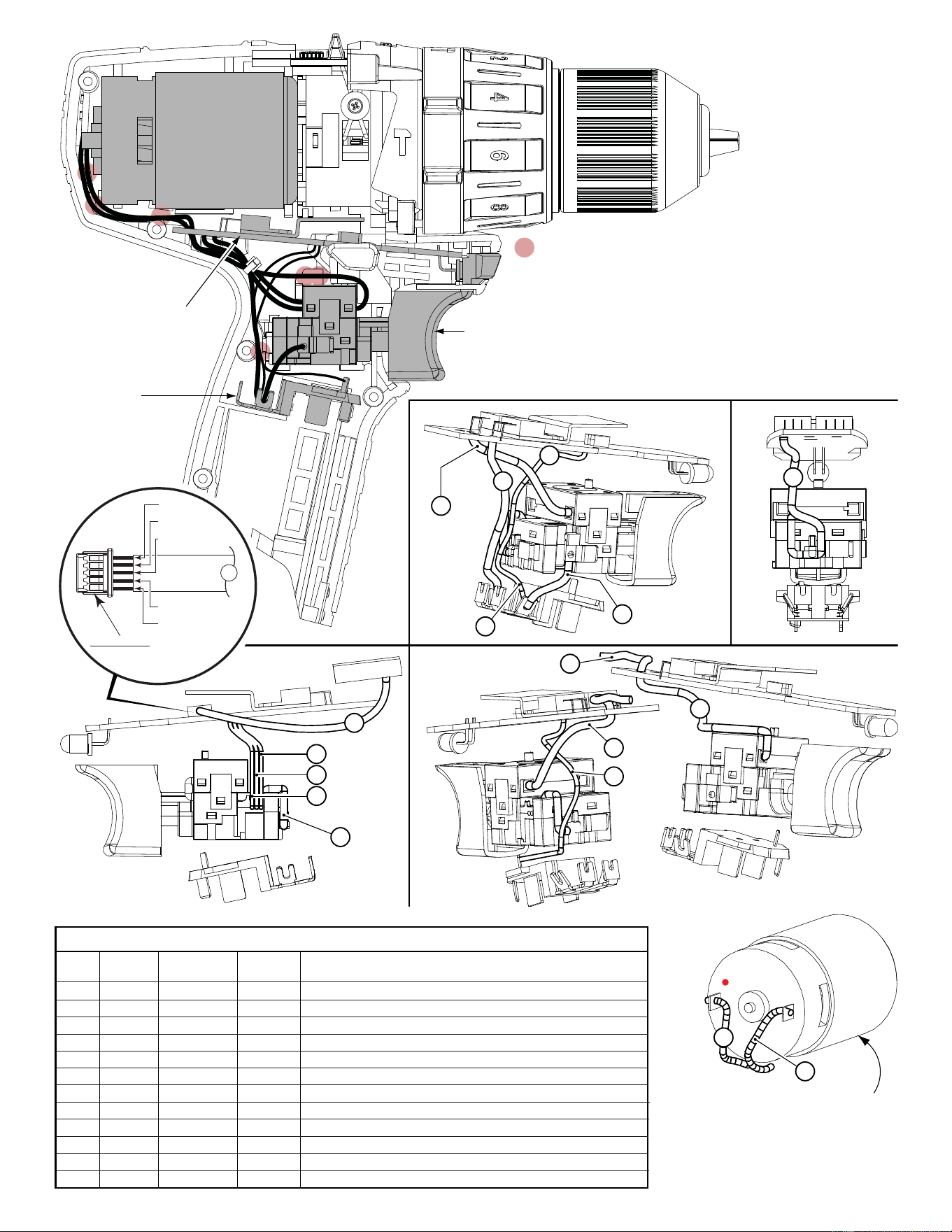
= WIRE TRAPS
or GUIDES
White
WHITE
BLACK
RED
GREEN
GRAY
13
PINNED SIDE OF CONNECTOR
TO FACE DOWN WHEN
INSTALLING TO
PC BOARD
MOTOR
ASSEMBLY
FUEL GUAGE
LED ASSY.
SLEEVED WIRES
(White, black, red,
green and
gray)
AS AN AID TO REASSEMBLY, TAKE NOTICE OF WIRE ROUTING AND
POSITION IN WIRE GUIDES AND TRAPS WHILE DISMANTLING TOOL
BE CAREFUL AND
AVOID PINCHING
WIRES BETWEEN
HANDLE HALVES
WHEN ASSEMBLING.
PCB
CONNECTOR
BLOCK
SWITCH
‘Red dot’ (positive terminal) is to be
placed down in left
handle halve.
Orient motor assembl
y
with slot to the bottom.
10
11
12
13
3
3
2
2
1
1
4
8
7
6
9
Black
Red
8
Black
Red
Red
Black
Yellow
Blue
Black
Black
1
White
Red
Black
Terminals, Connectors and 1 or 2 End Wire Preparation
Wire
Color
Origin or
Gauge
Wire
No.
Length
WIRING SPECIFICATIONS
1 Black 23-30-0830 ----- Component of the motor assembly.
2 Red 23-30-0830 ----- Component of the motor assembly.
3 Black 23-66-4000 ----- Component of the switch assembly.
4 Black 23-66-4000 ----- Component of the switch assembly.
6 White 23-66-4000 ----- Component of the switch assembly.
7 White 23-66-4000 ----- Component of the switch assembly.
8 Red 23-66-4000 ----- Component of the switch assembly.
9 Red 23-66-4000 ----- Component of the switch assembly.
10 Yellow 23-66-4000 ----- Component of the switch assembly.
11 Blue 23-66-4000 ----- Component of the switch assembly.
12 Black 23-66-4000 ----- Component of the switch assembly.
13 Sleeve 23-66-4000 ----- Component of the switch assembly / fuel gauge LED.