
DO NOT DISCARD – GIVE TO USER
WARNING
BEFORE USE
Study, understand and follow all instructions provided with this
product. Read these instructions carefully before installing, operating,
servicing or repairing this tool. Keep these instructions in a safe
accessible place.
INTENDED USE OF THE TOOL
WARNING
MADE IN CHINA
to Matco specifications
This tool is intended to be used to install metric M8, M10, M12 and
SAE 5/16"-18, 3/8"-16, 1/2"-13 standard length rivet nuts. Do not use
this tool outside of the designed intent. Never modify the tool for
any other purpose or use.
The manufacturer warrants this product to the original user against
defective material or workmanship for a period of 1 year from the
date of purchase.
The manufacturer reserves the right to determine whether the part
or parts failed because of defective material, workmanship or other
causes. Failures caused by accident, alteration or misuse are not
covered by this warranty.
The manufacturer, at its discretion, will repair or replace product
covered under this warranty free of charge. Repairs or replacements
of products covered under this warranty are warranted for the
remainder of the original warranty period.
The manufacturer or its authorized service representatives must
perform all warranty repairs. Any repair to the product by
unauthorized service representatives voids this warranty. The rights
under this warranty are limited to the original user and may not be
transferred to subsequent owners.
The warranty is in lieu of all other warranties, expressed or implied,
including warranties of merchantability and fitness for a particular
purpose. Some states do not allow the exclusion or limitations of
incidental or consequential damages, so the above limitations may
not apply to you.
1 YEAR LIMITED WARRANTY
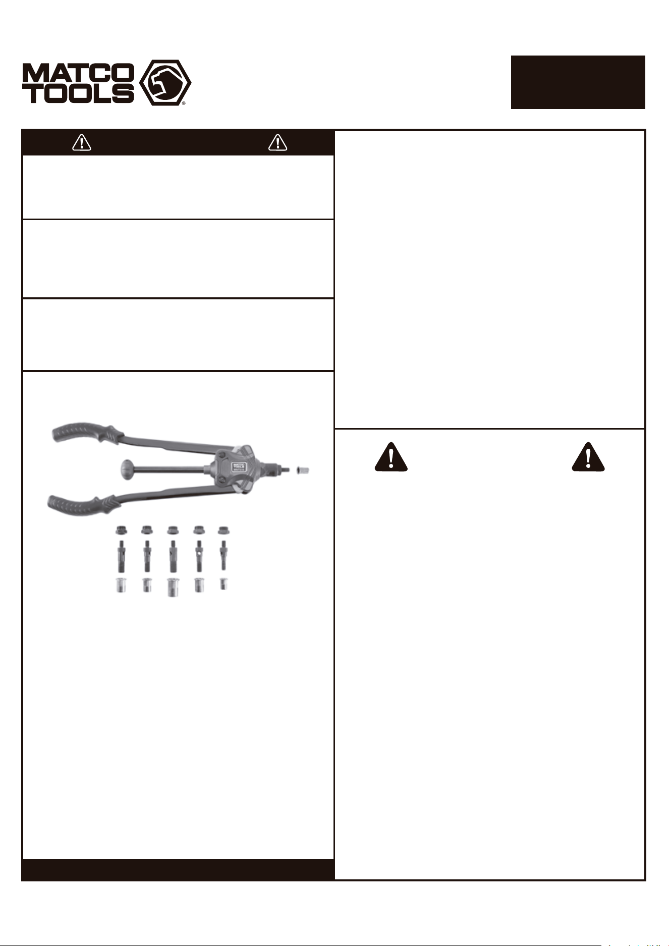
Before use, check the parts diagram and part number listing on
page 4 to make sure all parts are included. If any parts are missing
or damaged, please call your distributor.
Caution: To help prevent personal injury
Normal use of this product is likely to expose the user to dust and/
or microscopic particles containing chemicals known to the State of
California to cause cancer, birth defects or other reproductive harm.
Always wear appropriate safety equipment and clothing when
using this product. Study, understand and follow all instructions
provided with this product. Failure to read and follow all warnings
and operating instructions may result in damages and serious
injury or death.
• Always wear ANSI approved goggles when using this product
(users and bystanders).
• Never use this tool for any application other than for which
it was designed.
• Only use accessories designed for this tool.
• Never alter or modify this tool in any way.
• Improper operation and/or maintenance of the tool, modification
of the tool or use of the tool with accessories not designed for it
could result in serious injury or death.
• Always select the correct accessories of the correct size and
design for the job that you are attempting to perform.
• Always work in a clean, safe, well-lit, organized and adequately
equipped area.
• Do not begin repairs without assurance that vehicle is in secure
position and will not move during repair.
PRODUCT INFORMATION
SPECIFICATIONS
Weight: 3.30 lbs. (1500g)
Tool Length: 15" (380mm)
Max. Working Stroke: 9mm
Arm Force Multiplier: 38
Page 1
MNTS15
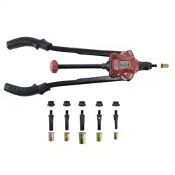
LARGE CAPACITY
RIVET NUT KIT
1806118-14
Work faster. Change mandrel sizes by hand without wrenches
using unique quick-change design.
Large size coverage. Includes metric sizes M8, M10, M12 and
SAE 5/16"-18, 3/8"-16, 1/2"-13 mandrels, nose pieces and
10 piece rivet nuts each.
Maximum strength. Double compound hinge design
outputs 38 times the input force.
Assembly direction
Assembly direction
Page 2
MNTS15
LARGE CAPACITY
RIVET NUT KIT
WARNING
Always wear ANSI approved safety goggles when using this
product (Users and Bystanders). Failure to read and follow all
warnings and operating instructions may result in damages
and serious injuries or death.
OPERATING INSTRUCTIONS
1. Choose the rivet nut size to be installed.
2. Install the correct size mandrel/nosepiece for the rivet nut to be
installed. See photos and instructions for changing the
mandrel/nosepiece and adjustment.
3. Drill a hole in the work product the same size or slightly larger
than the outside diameter of the rivet nut to be installed.
4. To install the rivet nut, open the handles outward as far as
possible and thread the rivet nut clockwise onto the mandrel (for
additional leverage, leave 1-2 turns gap between rivet nut and
nosepiece as long as there remains adequate thread engagement
on rivet nut).
5. Insert the rivet nut fastened to the riveter into the pre-drilled hole
until flush with the work product and pull handles inward to
secure the rivet nut into the hole. If the rivet nut is loose in the
hole, open the handles outward, turn #7 knob clockwise and pull
handles inward until the rivet nut feels secure in the hole. Repeat
as necessary until the rivet nut is secure in the hole. See
adjustment instructions if necessary.
6. Turn the #7 knob counterclockwise until the mandrel is removed
from the rivet nut. The rivet nut installation is complete if the rivet
nut is secure from movement in the hole.
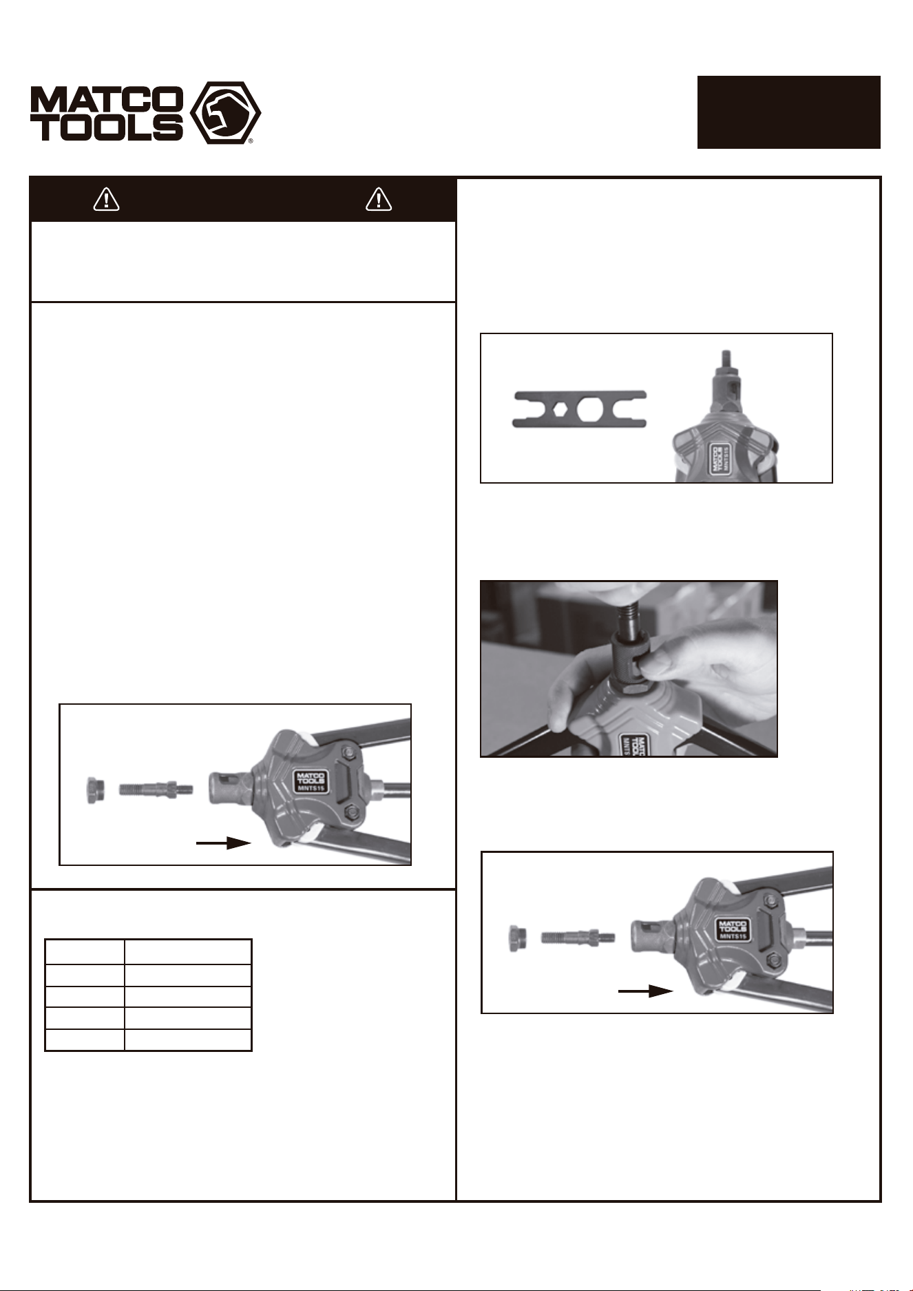
1. Remove and install the mandrel and nosepieces. Always keep
the matched mandrel/nosepiece sets together.
2. Remove nosepiece from #21 sleeve by unthreading the nose
piece counterclockwise. This can be done either by hand or with
the provided wrench if too tight to do so.
CHANGING MANDREL/
NOSEPIECE INSTRUCTIONS
3. Open the arms slightly, and using your thumbnail or tool, press
down to depress the inner hexagonal sleeve that sits within the
#21 outer sleeve. This should expose the lower hex portion of the
mandrel.
4. Unthread the mandrel by hand to remove it from the sleeve. Once
the mandrel has been threaded out far enough to clear the spring
loaded hex sleeve you may release tension on this sleeve collar.
5. Choose the correct mandrel/nosepiece to be installed.
6. Thread the new mandrel into the tool by hand until it approaches
the spring loaded hex sleeve and fully depress this sleeve to allow
the mandrel to be threaded further until it stops. The mandrel
does not need to be torqued. Release the hex sleeve and allow it
to fully reengage the mandrel. If the mandrel and hex sleeve do
not initially align, rotate the #7 knob while holding onto the
mandrel until it clicks up and reengages.
7. Thread the matching nose piece into the #21 by hand. Torquing
the nose piece is optional.
1806118-14
DRILL SIZE GUIDE
Size
M8 & 5/16"
M10 & 3/8"
M12
1/2"
Drill Hole
11mm or 7/16"
13mm or 17/32"
15mm or 19/32"
17.5mm or 11/16"
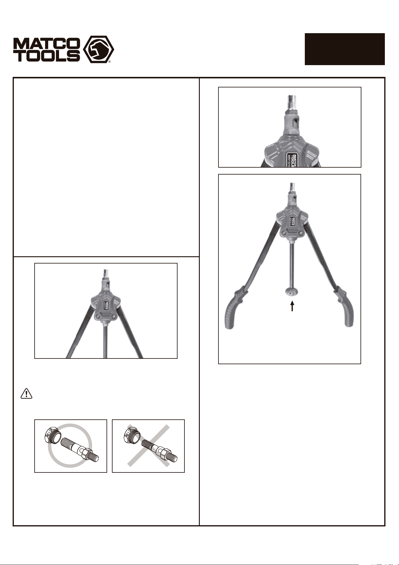
Riveter properly prepared for setting rivet nuts.
The arms do not need to be 100% extended.
Store matching nosepieces and mandrels
together when not in use to prevent mismatching
the sizes and for convenience.
M10
M10
M10
M8
M10
M8
Turn knob
counterclockwise
after rivet nut
setting is
complete to
remove riveter
from the rivet nut
Open handles
and thread
rivet nut
onto mandrel
LARGE CAPACITY
RIVET NUT KIT
Page 3
MNTS15
ADJUSTMENT INSTRUCTIONS
1. Proper adjustment of the riveter is necessary for efficient and easy
operation. Additionally, lubricating the tool joints may lessen the
effort needed to set rivet nuts.
2. The adjustment of the riveter will vary, depending on the size and
type of rivet nut being used and the hole size.
3. Adjust the riveter by opening the handles outward as far as
possible loosening the #21 outer sleeve clockwise to increase the
number of threads on the mandrel protruding beyond the
nosepiece for larger rivet nuts, and by turning the #21 outer sleeve
counterclockwise for smaller rivet nuts. Once adjustment is set,
tighten using the hex flats of the sleeve. Fine adjustment can be
made by turning the rivet nut on the mandrel to position the rivet
nut closer or further away from the nosepiece, as long as the
mandrel is threaded sufficiently into the rivet nut.
4. Always ensure that the mandrel is threaded into at least 80% of
the threads of the rivet nut to prevent damage to the threads on
the mandrel and/or the rivet nut.
5. If the handles are extended too far outward to provide enough
leverage to pull the handles inward to set the rivet nut, turn the
#21 outer sleeve clockwise or turn the rivet nut counterclockwise
slightly to change the handle angle to provide the proper leverage.
1806118-14
This tool is intended to be used to install metric M8, M10, M12 and
SAE 5/16"-18, 3/8"-16, 1/2"-13 standard length rivet nuts. Do not use
this tool outside of the designed intent. Never modify the tool for
any other purpose or use.
Weight: 3.30 lbs. (1500g)
Tool Length: 15" (380mm)
Max. Working Stroke: 9mm
Arm Force Multiplier: 38
Work faster. Change mandrel sizes by hand without wrenches
using unique quick-change design.
Large size coverage. Includes metric sizes M8, M10, M12 and
SAE 5/16"-18, 3/8"-16, 1/2"-13 mandrels, nose pieces and
10 piece rivet nuts each.
Maximum strength. Double compound hinge design
outputs 38 times the input force.
DO NOT DISCARD – GIVE TO USER
WARNING
BEFORE USE
Study, understand and follow all instructions provided with this
product. Read these instructions carefully before installing, operating,
servicing or repairing this tool. Keep these instructions in a safe
accessible place.
INTENDED USE OF THE TOOL
WARNING
MADE IN CHINA
to Matco specifications
The manufacturer warrants this product to the original user against
defective material or workmanship for a period of 1 year from the
date of purchase.
The manufacturer reserves the right to determine whether the part
or parts failed because of defective material, workmanship or other
causes. Failures caused by accident, alteration or misuse are not
covered by this warranty.
The manufacturer, at its discretion, will repair or replace product
covered under this warranty free of charge. Repairs or replacements
of products covered under this warranty are warranted for the
remainder of the original warranty period.
The manufacturer or its authorized service representatives must
perform all warranty repairs. Any repair to the product by
unauthorized service representatives voids this warranty. The rights
under this warranty are limited to the original user and may not be
transferred to subsequent owners.
The warranty is in lieu of all other warranties, expressed or implied,
including warranties of merchantability and fitness for a particular
purpose. Some states do not allow the exclusion or limitations of
incidental or consequential damages, so the above limitations may
not apply to you.
1 YEAR LIMITED WARRANTY
Before use, check the parts diagram and part number listing on
page 4 to make sure all parts are included. If any parts are missing
or damaged, please call your distributor.
Caution: To help prevent personal injury
Normal use of this product is likely to expose the user to dust and/
or microscopic particles containing chemicals known to the State of
California to cause cancer, birth defects or other reproductive harm.
Always wear appropriate safety equipment and clothing when
using this product. Study, understand and follow all instructions
provided with this product. Failure to read and follow all warnings
and operating instructions may result in damages and serious
injury or death.
• Always wear ANSI approved goggles when using this product
(users and bystanders).
• Never use this tool for any application other than for which
it was designed.
• Only use accessories designed for this tool.
• Never alter or modify this tool in any way.
• Improper operation and/or maintenance of the tool, modification
of the tool or use of the tool with accessories not designed for it
could result in serious injury or death.
• Always select the correct accessories of the correct size and
design for the job that you are attempting to perform.
• Always work in a clean, safe, well-lit, organized and adequately
equipped area.
• Do not begin repairs without assurance that vehicle is in secure
position and will not move during repair.
PRODUCT INFORMATION
SPECIFICATIONS
Page 1
MNTS15
LARGE CAPACITY
RIVET NUT KIT
1806118-14
西文
(Spanish)
(Spanish)

Assembly direction
Assembly direction
WARNING
Always wear ANSI approved safety goggles when using this
product (Users and Bystanders). Failure to read and follow all
warnings and operating instructions may result in damages
and serious injuries or death.
OPERATING INSTRUCTIONS
1. Choose the rivet nut size to be installed.
2. Install the correct size mandrel/nosepiece for the rivet nut to be
installed. See photos and instructions for changing the
mandrel/nosepiece and adjustment.
3. Drill a hole in the work product the same size or slightly larger
than the outside diameter of the rivet nut to be installed.
4. To install the rivet nut, open the handles outward as far as
possible and thread the rivet nut clockwise onto the mandrel (for
additional leverage, leave 1-2 turns gap between rivet nut and
nosepiece as long as there remains adequate thread engagement
on rivet nut).
5. Insert the rivet nut fastened to the riveter into the pre-drilled hole
until flush with the work product and pull handles inward to
secure the rivet nut into the hole. If the rivet nut is loose in the
hole, open the handles outward, turn #7 knob clockwise and pull
handles inward until the rivet nut feels secure in the hole. Repeat
as necessary until the rivet nut is secure in the hole. See
adjustment instructions if necessary.
6. Turn the #7 knob counterclockwise until the mandrel is removed
from the rivet nut. The rivet nut installation is complete if the rivet
nut is secure from movement in the hole.
1. Remove and install the mandrel and nosepieces. Always keep
the matched mandrel/nosepiece sets together.
2. Remove nosepiece from #21 sleeve by unthreading the nose
piece counterclockwise. This can be done either by hand or with
the provided wrench if too tight to do so.
CHANGING MANDREL/
NOSEPIECE INSTRUCTIONS
3. Open the arms slightly, and using your thumbnail or tool, press
down to depress the inner hexagonal sleeve that sits within the
#21 outer sleeve. This should expose the lower hex portion of the
mandrel.
4. Unthread the mandrel by hand to remove it from the sleeve. Once
the mandrel has been threaded out far enough to clear the spring
loaded hex sleeve you may release tension on this sleeve collar.
5. Choose the correct mandrel/nosepiece to be installed.
6. Thread the new mandrel into the tool by hand until it approaches
the spring loaded hex sleeve and fully depress this sleeve to allow
the mandrel to be threaded further until it stops. The mandrel
does not need to be torqued. Release the hex sleeve and allow it
to fully reengage the mandrel. If the mandrel and hex sleeve do
not initially align, rotate the #7 knob while holding onto the
mandrel until it clicks up and reengages.
7. Thread the matching nose piece into the #21 by hand. Torquing
the nose piece is optional.
DRILL SIZE GUIDE
Size
M8 & 5/16"
M10 & 3/8"
M12
1/2"
Drill Hole
11mm or 7/16"
13mm or 17/32"
15mm or 19/32"
17.5mm or 11/16"
Page 2
MNTS15
LARGE CAPACITY
RIVET NUT KIT
1806118-14
(Spanish)

Riveter properly prepared for setting rivet nuts.
The arms do not need to be 100% extended.
Store matching nosepieces and mandrels
together when not in use to prevent mismatching
the sizes and for convenience.
M10
M10
M10
M8
M10
M8
Turn knob
counterclockwise
after rivet nut
setting is
complete to
remove riveter
from the rivet nut
Open handles
and thread
rivet nut
onto mandrel
LARGE CAPACITY
RIVET NUT KIT
Page 3
MNTS15
ADJUSTMENT INSTRUCTIONS
1. Proper adjustment of the riveter is necessary for efficient and easy
operation. Additionally, lubricating the tool joints may lessen the
effort needed to set rivet nuts.
2. The adjustment of the riveter will vary, depending on the size and
type of rivet nut being used and the hole size.
3. Adjust the riveter by opening the handles outward as far as
possible loosening the #21 outer sleeve clockwise to increase the
number of threads on the mandrel protruding beyond the
nosepiece for larger rivet nuts, and by turning the #21 outer sleeve
counterclockwise for smaller rivet nuts. Once adjustment is set,
tighten using the hex flats of the sleeve. Fine adjustment can be
made by turning the rivet nut on the mandrel to position the rivet
nut closer or further away from the nosepiece, as long as the
mandrel is threaded sufficiently into the rivet nut.
4. Always ensure that the mandrel is threaded into at least 80% of
the threads of the rivet nut to prevent damage to the threads on
the mandrel and/or the rivet nut.
5. If the handles are extended too far outward to provide enough
leverage to pull the handles inward to set the rivet nut, turn the
#21 outer sleeve clockwise or turn the rivet nut counterclockwise
slightly to change the handle angle to provide the proper leverage.
1806118-14
(Spanish)

This tool is intended to be used to install metric M8, M10, M12 and
SAE 5/16"-18, 3/8"-16, 1/2"-13 standard length rivet nuts. Do not use
this tool outside of the designed intent. Never modify the tool for
any other purpose or use.
Weight: 3.30 lbs. (1500g)
Tool Length: 15" (380mm)
Max. Working Stroke: 9mm
Arm Force Multiplier: 38
Work faster. Change mandrel sizes by hand without wrenches
using unique quick-change design.
Large size coverage. Includes metric sizes M8, M10, M12 and
SAE 5/16"-18, 3/8"-16, 1/2"-13 mandrels, nose pieces and
10 piece rivet nuts each.
Maximum strength. Double compound hinge design
outputs 38 times the input force.
DO NOT DISCARD – GIVE TO USER
WARNING
BEFORE USE
Study, understand and follow all instructions provided with this
product. Read these instructions carefully before installing, operating,
servicing or repairing this tool. Keep these instructions in a safe
accessible place.
INTENDED USE OF THE TOOL
WARNING
MADE IN CHINA
to Matco specifications
The manufacturer warrants this product to the original user against
defective material or workmanship for a period of 1 year from the
date of purchase.
The manufacturer reserves the right to determine whether the part
or parts failed because of defective material, workmanship or other
causes. Failures caused by accident, alteration or misuse are not
covered by this warranty.
The manufacturer, at its discretion, will repair or replace product
covered under this warranty free of charge. Repairs or replacements
of products covered under this warranty are warranted for the
remainder of the original warranty period.
The manufacturer or its authorized service representatives must
perform all warranty repairs. Any repair to the product by
unauthorized service representatives voids this warranty. The rights
under this warranty are limited to the original user and may not be
transferred to subsequent owners.
The warranty is in lieu of all other warranties, expressed or implied,
including warranties of merchantability and fitness for a particular
purpose. Some states do not allow the exclusion or limitations of
incidental or consequential damages, so the above limitations may
not apply to you.
1 YEAR LIMITED WARRANTY
Before use, check the parts diagram and part number listing on
page 4 to make sure all parts are included. If any parts are missing
or damaged, please call your distributor.
Caution: To help prevent personal injury
Normal use of this product is likely to expose the user to dust and/
or microscopic particles containing chemicals known to the State of
California to cause cancer, birth defects or other reproductive harm.
Always wear appropriate safety equipment and clothing when
using this product. Study, understand and follow all instructions
provided with this product. Failure to read and follow all warnings
and operating instructions may result in damages and serious
injury or death.
• Always wear ANSI approved goggles when using this product
(users and bystanders).
• Never use this tool for any application other than for which
it was designed.
• Only use accessories designed for this tool.
• Never alter or modify this tool in any way.
• Improper operation and/or maintenance of the tool, modification
of the tool or use of the tool with accessories not designed for it
could result in serious injury or death.
• Always select the correct accessories of the correct size and
design for the job that you are attempting to perform.
• Always work in a clean, safe, well-lit, organized and adequately
equipped area.
• Do not begin repairs without assurance that vehicle is in secure
position and will not move during repair.
PRODUCT INFORMATION
SPECIFICATIONS
Page 1
MNTS15
LARGE CAPACITY
RIVET NUT KIT
1806118-14
(French)

Assembly direction
Assembly direction
DRILL SIZE GUIDE
WARNING
Always wear ANSI approved safety goggles when using this
product (Users and Bystanders). Failure to read and follow all
warnings and operating instructions may result in damages
and serious injuries or death.
OPERATING INSTRUCTIONS
1. Choose the rivet nut size to be installed.
2. Install the correct size mandrel/nosepiece for the rivet nut to be
installed. See photos and instructions for changing the
mandrel/nosepiece and adjustment.
3. Drill a hole in the work product the same size or slightly larger
than the outside diameter of the rivet nut to be installed.
4. To install the rivet nut, open the handles outward as far as
possible and thread the rivet nut clockwise onto the mandrel (for
additional leverage, leave 1-2 turns gap between rivet nut and
nosepiece as long as there remains adequate thread engagement
on rivet nut).
5. Insert the rivet nut fastened to the riveter into the pre-drilled hole
until flush with the work product and pull handles inward to
secure the rivet nut into the hole. If the rivet nut is loose in the
hole, open the handles outward, turn #7 knob clockwise and pull
handles inward until the rivet nut feels secure in the hole. Repeat
as necessary until the rivet nut is secure in the hole. See
adjustment instructions if necessary.
6. Turn the #7 knob counterclockwise until the mandrel is removed
from the rivet nut. The rivet nut installation is complete if the rivet
nut is secure from movement in the hole.
1. Remove and install the mandrel and nosepieces. Always keep
the matched mandrel/nosepiece sets together.
2. Remove nosepiece from #21 sleeve by unthreading the nose
piece counterclockwise. This can be done either by hand or with
the provided wrench if too tight to do so.
CHANGING MANDREL/
NOSEPIECE INSTRUCTIONS
3. Open the arms slightly, and using your thumbnail or tool, press
down to depress the inner hexagonal sleeve that sits within the
#21 outer sleeve. This should expose the lower hex portion of the
mandrel.
4. Unthread the mandrel by hand to remove it from the sleeve. Once
the mandrel has been threaded out far enough to clear the spring
loaded hex sleeve you may release tension on this sleeve collar.
5. Choose the correct mandrel/nosepiece to be installed.
6. Thread the new mandrel into the tool by hand until it approaches
the spring loaded hex sleeve and fully depress this sleeve to allow
the mandrel to be threaded further until it stops. The mandrel
does not need to be torqued. Release the hex sleeve and allow it
to fully reengage the mandrel. If the mandrel and hex sleeve do
not initially align, rotate the #7 knob while holding onto the
mandrel until it clicks up and reengages.
7. Thread the matching nose piece into the #21 by hand. Torquing
the nose piece is optional.
Size
M8 & 5/16"
M10 & 3/8"
M12
1/2"
Drill Hole
11mm or 7/16"
13mm or 17/32"
15mm or 19/32"
17.5mm or 11/16"
Page 2
MNTS15
LARGE CAPACITY
RIVET NUT KIT
1806118-14
(French)

Riveter properly prepared for setting rivet nuts.
The arms do not need to be 100% extended.
Store matching nosepieces and mandrels
together when not in use to prevent mismatching
the sizes and for convenience.
M10
M10
M10
M8
M10
M8
Turn knob
counterclockwise
after rivet nut
setting is
complete to
remove riveter
from the rivet nut
Open handles
and thread
rivet nut
onto mandrel
LARGE CAPACITY
RIVET NUT KIT
Page 3
MNTS15
ADJUSTMENT INSTRUCTIONS
1. Proper adjustment of the riveter is necessary for efficient and easy
operation. Additionally, lubricating the tool joints may lessen the
effort needed to set rivet nuts.
2. The adjustment of the riveter will vary, depending on the size and
type of rivet nut being used and the hole size.
3. Adjust the riveter by opening the handles outward as far as
possible loosening the #21 outer sleeve clockwise to increase the
number of threads on the mandrel protruding beyond the
nosepiece for larger rivet nuts, and by turning the #21 outer sleeve
counterclockwise for smaller rivet nuts. Once adjustment is set,
tighten using the hex flats of the sleeve. Fine adjustment can be
made by turning the rivet nut on the mandrel to position the rivet
nut closer or further away from the nosepiece, as long as the
mandrel is threaded sufficiently into the rivet nut.
4. Always ensure that the mandrel is threaded into at least 80% of
the threads of the rivet nut to prevent damage to the threads on
the mandrel and/or the rivet nut.
5. If the handles are extended too far outward to provide enough
leverage to pull the handles inward to set the rivet nut, turn the
#21 outer sleeve clockwise or turn the rivet nut counterclockwise
slightly to change the handle angle to provide the proper leverage.
1806118-14
(French)
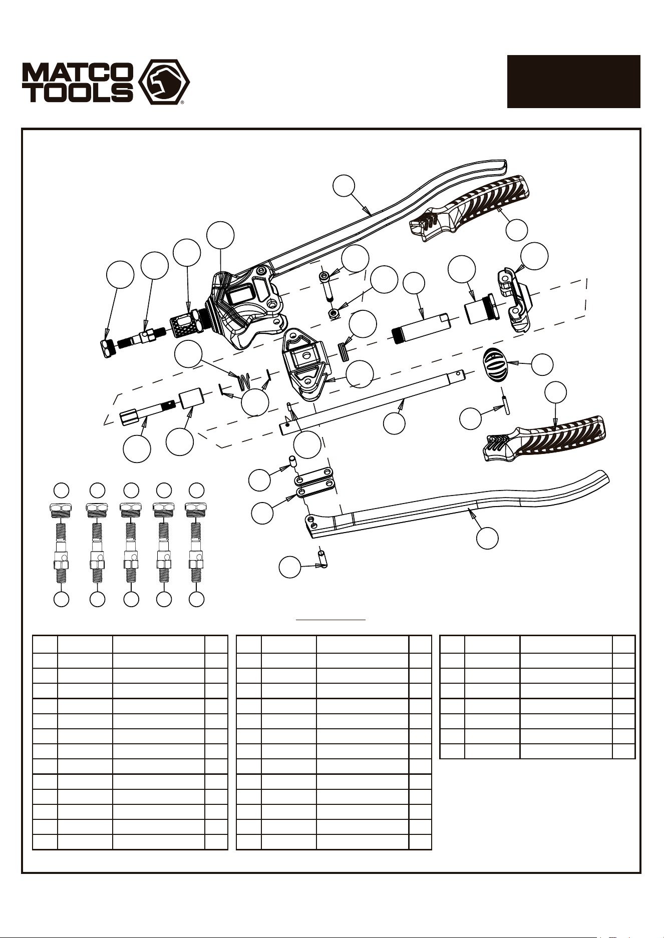
MNTS15-01
MNTS15-02
MNTS15-03
MNTS15-04
MNTS15-05
MNTS15-06
MNTS15-07
MNTS15-08
MNTS15-09
MNTS15-10
MNTS15-11
MNTS15-12
MNTS15-13
1
2
3
4
5
6
7
8
9
10
11
12
13
Handle Sleeve
Handle
3*32 Open Spring Pin
6*25 Pin Rod
Connecting Rod
6*13 Pin Rod
Reversing Knob
Knob Arm
Short Sleeve
Sleeve Rod Screw
Body Cover
Pressure Bearing
Pull Rod Base
2
2
1
2
4
2
1
1
1
1
1
1
1
Index Part No. Description Qty
MNTS15-14
MNTS15-15
MNTS15-16
MNTS15-17
MNTS15-18
MNTS15-19
MNTS15-20
1452-21
1442-A02
1442-A01
1452-26
1452-24
1442-A26
14
15
16
17
18
19
20
21
22
23
24
25
26
Spacer
Spring
Stationary Sleeve
Pull Rod
6*42 Screw Arbor
M6 Loosen Nut
Aluminum Body
Sleeve
M8 Mandrel
M8 Nosepiece
M10 Mandrel
M12 Mandrel
5/16" Mandrel
2
1
1
1
2
2
1
1
1
1
1
1
1
Index Part No. Description Qty
1452-30
1452-28
1452-27
1452-25
1442-A27
1452-31
1452-29
27
28
29
30
31
32
33
3/8" Mandrel
1/2" Mandrel
M10 Nosepiece
M12 Nosepiece
5/16" Nosepiece
3/8" Nosepiece
1/2" Nosepiece
1
1
1
1
1
1
1
Index Part No. Description Qty
Parts List
1
2
1
2
4
5
6
7
3
8
9
10
11
12
13
14
15
16
17
18
19
20
21
22
23
24
M8
24 25 26 27 28
29 30 31 32 33
M10
M12
5/16"
3/8"
1/2"
LARGE CAPACITY
RIVET NUT KIT
PARTS BREAKDOWN
805
Page 4
MNTS15
1806118-14