
49
48
3g
3d
3e
47
6
46
40b
41
42
43
40a
45c
44
45a
45d
45b
3a
3b
1
3c
2
5a
13
23a
38
36
40a
40b
40
45a 45b
45c 45d
45
41 42
43
52
3f
5b
5c
4
5d
6
7
5a 5b 5c
5d 5e 48
5
22
2723b
28
51
37
54
31
53
29
39
35
32
26
25
30
23a 23b
27
23
6 46
47
56
34
33
33
34
60
3a 3b 3c 3d 3e
3f 3g 7 46
3
5e
15
16
17
18
19
21
15 16
17 18
50
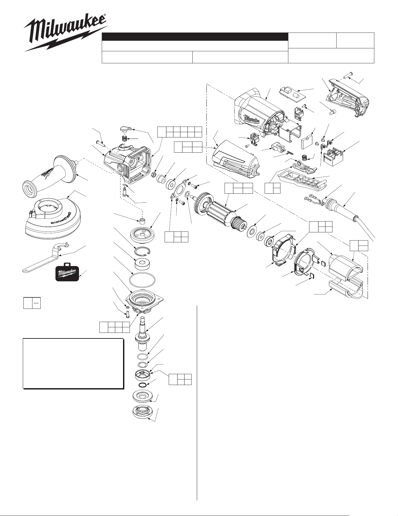
*LUBRICATION NOTE:
When servicing the Gears (5a & 48)
or the Gearcase (3c), 90-95% of the
old grease must be removed prior
to new grease being added.
FIG. LUBRICATION*
5a,48 Type "Y" Grease, No. 49-08-5270,
Must Be Applied To All Gear Teeth.
EXAMPLE:
Component Parts (Small #)
Are Included When Ordering
The Assembly (Large #).
0
00
FIG. PART NO. DESCRIPTION OF PART NO. REQ.
27 05-88-1300 M4 x 28mm Pan Hd. ST Screw T-20 (4)
28 22-09-1820 PCB Assembly (1)
29 23-74-1620 Terminal (1)
30 23-74-1615 Terminal (1)
31 23-66-2665 On-OSwitch (1)
32 31-92-0255 Paddle Trigger (1)
33 --------------- Paddle Trigger Spring (1)
34 --------------- Paddle Linkage (1)
35 40-50-1155 LockButtonSpring (1)
36 42-42-0495 Lock-OnButton (1)
37 05-88-0030 M3 x 8.5mm Pan Hd. ST Screw T-10 (2)
38 22-18-2240 CarbonBrushAssembly(Setof2) (1)
39 31-50-0685 MotorHousing (1)
40 18-07-0315 Field Assembly (1)
40a --------------- Field Halve (1)
40b --------------- Field Halve (1)
41 42-28-0085 Rubber Block (2)
42 --------------- BaeFoot (1)
43 --------------- Bae (1)
44 42-96-0016 Rubber Bearing Cap (1)
45 16-10-0850 ArmatureAssembly (1)
45a 02-04-2110 Ball Bearing (1)
45b --------------- Armature (1)
45c 45-88-0406 Washer (1)
45d 31-86-0090 PlasticDisc (1)
46 05-78-0105 M4x10mmPanHd.Tapt.ScrewT-20 (2)
47 44-86-0155 BearingRetainer (1)
48 --------------- Pinion (1)
49 05-55-0620 M5HexNut (1)
50 14-46-6105 FlangewithRampsAssembly (1)
51 22-56-0150 CloseEndConnector (1)
52 42-14-0520 BaeAssembly (1)
53 05-78-0305 M3.5x7mmPanHd.Phil.SwitchScr. (2)
54 23-16-0075 Foam Block (1)
55 12-20-1560 ServiceNameplate(NotShown) (1)
56 44-86-0145 BearingRetainingPlateAssembly (1)
60 14-46-6100 PaddleLinkage/SpringServiceKit (1)
FIG. PART NO. DESCRIPTION OF PART NO. REQ.
1 05-88-1650 M4 x 25mm Pan Hd. ST Screw T-20 (4)
2 42-62-0120 Side Handle Assembly (1)
3 14-30-1156 Gearcase Assembly (1)
3a --------------- SpindleLockButton (1)
3b --------------- Spindle Lock Spring (1)
3c --------------- Gearcase (1)
3d --------------- O-Ring (1)
3e --------------- Spindle Lock Pin (1)
3f --------------- NeedleBearing (1)
3g 02-04-0620 Ball Bearing (1)
4 34-40-0560 O-Ring (1)
5 14-46-0417 5/8"SpindleHubKit (1)
5a --------------- Spiral Bevel Gear (1)
5b --------------- RetainingRing (1)
5c --------------- Ball Bearing (1)
5d --------------- Spindle Hub (1)
5e --------------- 5/8" Spindle (1)
6 05-90-0225 SpringWasher (6)
7 05-78-5316 M4x14mmPanHd.Tapt.ScrewT-20 (4)
13 14-32-0210 4.5"Type27GuardAssembly(Shown) (1)
13 43-54-0920 4.5"Type1GuardAssy.(NotShown) (1)
15 --------------- O-Ring (1)
16 --------------- Wavey Spring (1)
17 --------------- FlangewithRamps (1)
18 --------------- RetainingRing (1)
19 43-34-0935 InnerDiscFlange (1)
21 44-40-0035 OuterFlangeNut (1)
22 49-96-7205 SpannerWrench (1)
23 14-34-6100 RearHandleSet (1)
23a --------------- LeftHandleHalve (1)
23b --------------- RightHandleHalve (1)
25 44-76-0095 CordProtector (1)
26 22-64-3430 Power Cord (1)
MILWAUKEE TOOL ● www.milwaukeetool.com
13135W.LisbonRoad,Brookeld,WI53005
Drwg.1
6146-30
54-38-2202
D02C
4.5" COMPACT ANGLE GRINDER with PADDLE SWITCH with lock-on
REVISEDBULLETIN
DATE
Sep. 2016
SERVICE PARTS LIST
BULLETIN NO.
WIRINGINSTRUCTION
CAT. NO.
SPECIFY CATALOG NO. AND SERIAL NO. WHEN ORDERING PARTS
STARTING
SERIALNUMBER
See Reverse Side
76
Canvas Tool Bag
No. 42-55-6148
54-38-2201
«
«
«= Part number change
frompreviousservice
partslist.
«
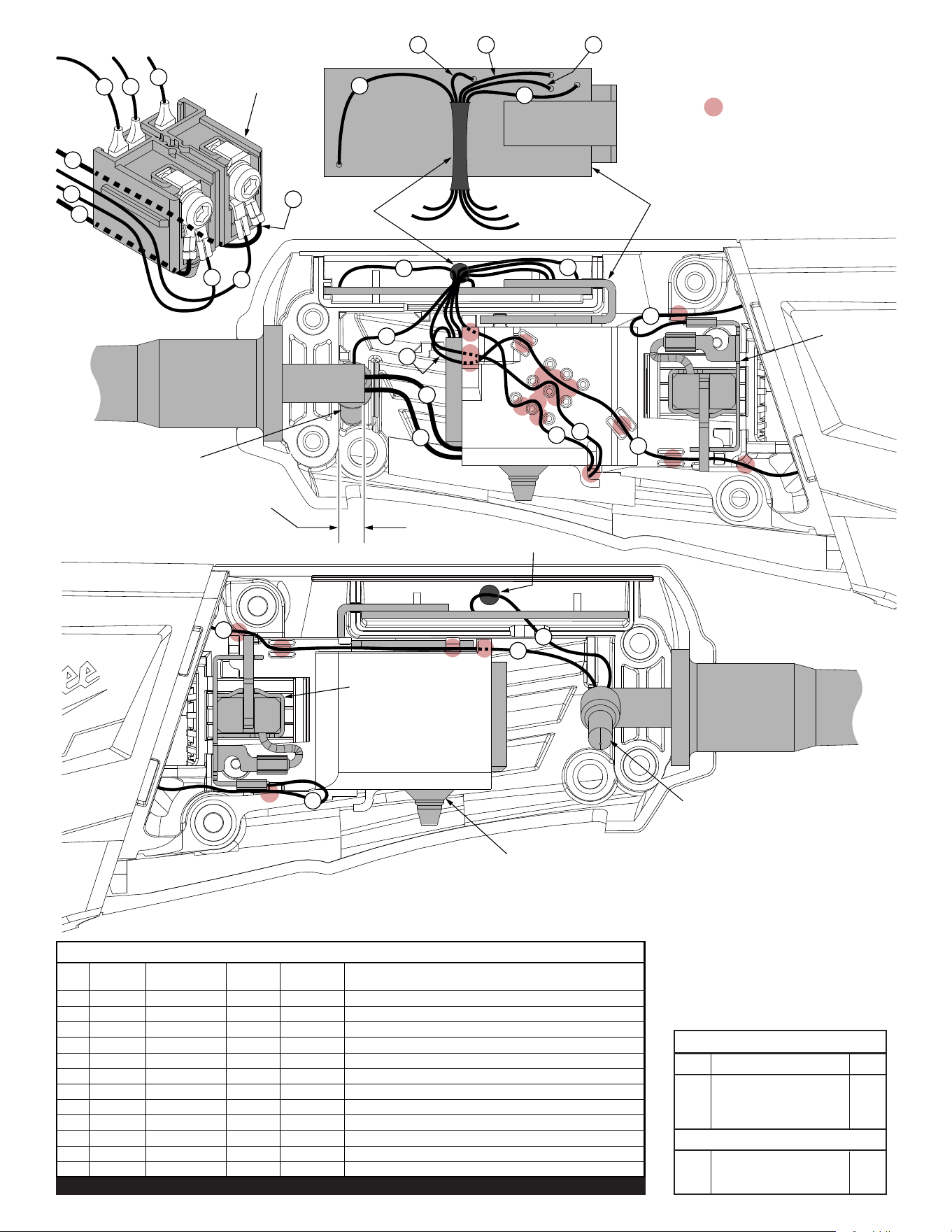
= WIRE TRAPS
or GUIDES
2
2
6
1
3
5
3
7
8
SLEEVE
SWITCH
PCB ASSEMBLY
Route wires
1 and 2 under
the switch.
Extend cord jacket approx. .25”
minimum beyond the clamping area.
Wire connector (C1)
Wire connector (C1)
SWITCH
RH BRUSH
ASSEMBLY
LH BRUSH
ASSEMBLY
5
7
6
3
4
3
3
6
7
4
8
8
9
1
2
4
10
10
11
SLEEVE
Wire Wire Origin or
No. Color PartNo. Gauge Length Terminals,ConnectorsandEndWirePreparation
1 Black 22-64-3430 -- -- ComponentofCordSet.ConnecttoSwitch.
2 White 22-64-3430 -- -- ComponentofCordSet.ConnecttoSwitch.
3 Black 22-09-1820 -- -- ComponentofPCBA.ConnecttoSwitch.
4 Red 22-09-1820 -- -- ComponentofPCBA.ConnecttoC1withwire#10.
5 White 22-09-1820 -- -- ComponentofPCBA.ConnecttoSwitch.
6 White 22-09-1820 -- -- ComponentofPCBA.ConnecttoSwitch.
7 Black 22-09-1820 -- -- ComponentofPCBA.ConnecttoSwitch.
8 Black 18-07-0315 -- -- ComponentofField.ConnecttoSwitch.
9 Black 18-07-0315 -- -- ComponentofField.ConnecttoRightBrushAssy.
10 Black 18-07-0315 -- -- ComponentofField.ConnecttoC1withwire#4.
11 Black 18-07-0315 -- -- ComponentofField.ConnecttoLeftBrushAssy.
BULK LEAD WIRE - BULLETIN 58-01-0003
WIRING SPECIFICATIONS
AS AN AID TO REASSEMBLY, TAKE NOTICE OF
WIRE ROUTING AND POSITION IN WIRE GUIDES
AND TRAPS WHILE DISMANTLING TOOL.
BE CAREFUL AND AVOID PINCHING WIRES
BETWEEN HANDLE HALVES WHEN ASSEMBLING.
Qnty.
TERMINAL DESCRIPTION
PartNo.Code
NOTE:
Allleadsmustbeheldto±1/16".
Allleadlengthsarebeforestripping.
CONNECTOR DESCRIPTION
C1 22-56-0150 1