
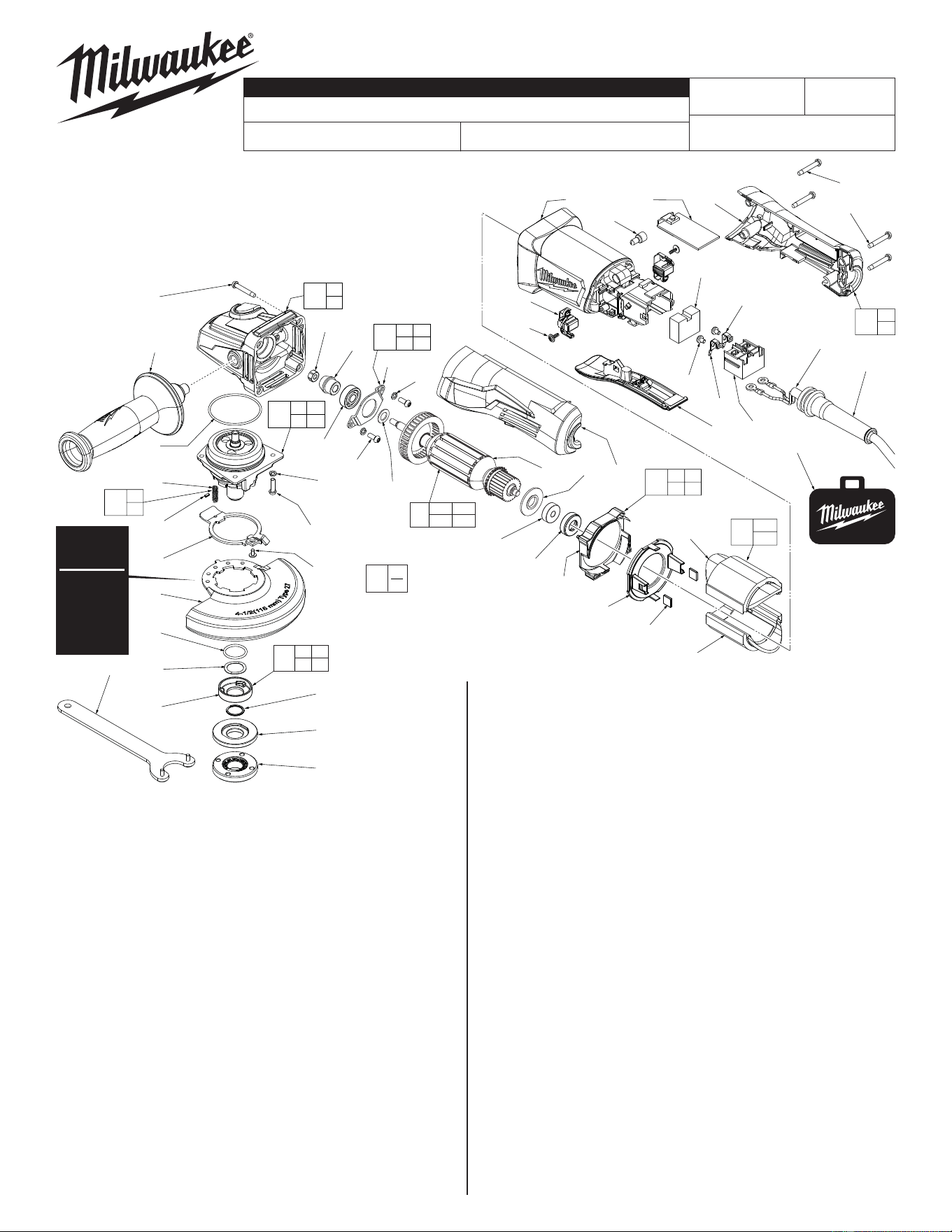
FIG. PART NO. DESCRIPTION OF PART NO. REQ.
39b --------------- Field Halve (1)
40 42-28-0085 Rubber Block (2)
41 --------------- Baffl e Foot (1)
42 --------------- Baffl e (1)
43 42-96-0405 Rubber Bearing Cap (1)
44 16-10-0850 Armature Assembly (1)
44a 02-04-2110 Ball Bearing (1)
44b 31-86-0090 Plastic Disc (1)
44c --------------- Armature (1)
44d 45-88-0406 Washer (1)
45 05-88-1280 M4 x 10mm Pan Hd. Mach. T-20 Screw (2)
46 44-86-0155 Bearing Retainer (1)
47 32-60-0301 Pinion (1)
48 05-55-0620 M5 Hex Nut (1)
49 12-20-6142 Service Nameplate (Not Shown) (1)
50 10-20-6142 Warning Label (Not Shown) (1)
53 05-78-0305 M3.5 x 7mm Pan Hd. Phillips Screw (2)
60 42-14-0520 Baffl e Assembly (1)
61 44-86-0145 Bearing Retaining Plate Assembly (1)
62 14-46-6105 Flange with Ramps Assembly (1)
65 14-46-0241 Spring/Pin Kit (1)
66 31-44-6101 Handle Set (1)
68 31-92-0210 Paddle Trigger Assembly (1)
70 42-55-6148 Canvas Tool Bag (Optional) (1)
FIG. PART NO. DESCRIPTION OF PART NO. REQ.
1 05-88-1650 M4 x 25mm Pan Hd. ST Screw T-20 (4)
2 42-62-0120 Side Handle Assembly (1)
3 14-30-0082 Gear Case Assembly (1)
3g 02-04-0620 Ball Bearing (1)
4 34-40-0180 O-Ring (1)
5 14-73-0460 Spindle Hub Assembly (1)
5d --------------- Steel Pin (1)
FIG. PART NO. DESCRIPTION OF PART NO. REQ.
5f --------------- Spring (1)
5g 44-20-0155 Guard Locking Tang (1)
5h 05-81-0020 M3 x 5mm Pan Hd. ST T-8 Screw (1)
6 05-90-0225 Spring Washer (6)
7 05-88-1210 M4 x 14mm Pan Hd. Mach. T-20 Screw (4)
8 43-54-1200 4.5" Type 27 Guard (Standard Equip.) (1)
9 --------------- O-Ring (1)
10 --------------- Wavey Spring (1)
11 --------------- Flange with Ramps (1)
12 --------------- Retaining Ring (1)
13 43-34-0935 Inner Disc Flange (1)
15 44-40-0035 Outer Flange Nut (1)
16 49-96-7215 Spanner Wrench (1)
21 05-88-1300 M4 x 28mm Pan Hd. ST T-20 Screw (2)
22 05-88-1200 M4 x 16mm Pan Hd. ST T-20 Screw (2)
23 44-76-0095 Cord Protector (1)
24 22-64-2021 Power Cord (1)
26 22-09-0720 PCBA (1)
27 23-66-2665 On-Off Switch (1)
28 23-74-1620 Brass Terminal (1)
29 23-74-1615 Brass Terminal (1)
32 22-18-2240 Carbon Brush Assembly (Set of 2) (1)
33 05-88-0030 M3 x 8.5mm Pan Hd. ST T-10 Screw (2)
34 31-50-6140 Motor Housing (1)
35 23-16-0075 Foam Block (1)
36 --------------- Handle Support, Left Handle Halve (1)
37 22-56-0150 Closed End Wire Connector (1)
38 --------------- Handle Cover, Right Handle Halve (1)
39 18-07-0315 Field Assembly (1)
39a --------------- Field Halve (1)
MILWAUKEE ELECTRIC TOOL CORPORATION
13135 W. Lisbon Road, Brookfi eld, WI 53005
Drwg. 1
6142-31
54-38-2330
H41A
4.5" COMPACT ANGLE GRINDER with PADDLE SWITCH
REVISED BULLETIN
DATE
June 2016
SERVICE PARTS LIST
BULLETIN NO.
WIRING INSTRUCTION
CAT. NO.
SPECIFY CATALOG NO. AND SERIAL NO. WHEN ORDERING PARTS
STARTING
SERIAL NUMBER
See Reverse Side
6 45
46
61
39a
39b
39
40 41
42
60
36
38
66
9 10
11 12
62
5d
5f
65
3g
3
4 5d
5f
5
1
(4x)
2
4
5f
5d
5g
8
9
10
11
3g
6
(4x)
7(4x)
5h
12
13
15
48
47
46
45
(2x)
44d
44a
43
44c 44b 36
41
40
(2x)
32(2x)
33(2x)
35
37
34
24
23
68
21(2x)
22(2x)
6
(2x)
39a
39b
42
16
70
44a 44b
44c 44d
44
26 38
29
27
53
28
FIG. LUBRICATION
Use Type 'Y' Grease, No. 49-08-5270
3,5,47 When servicing the Gear Case Assembly (3), Pinion (47) or
the Spindle Hub Assembly (5):
90-95% of the old grease must be removed prior to any new
grease being added. Be sure that all gear teeth are heavily
coated when reassembling.
EXAMPLE:
Component Parts (Small #)
Are Included When Ordering
The Assembly (Large #).
0
00
Type 27
Guard is
Std. Equip.
Optional
Type 1
Guard
available.
Order No.
43-54-1210.
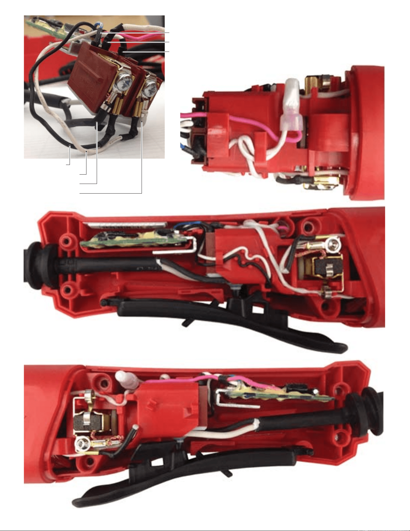
Black from PCBA
White (thin) from PCBA
Black from Power Cord
White from Power Cord
Blue from PCBA
White from bottom right Field
White (thick) from PCBA
TOP VIEW
HANDLE SUPPORT (Left Handle Halve)
Install all components and route wires here before
securing with Handle Cover.
HANDLE COVER (Right Handle Halve)
(6142-30 shown with Lock Button)
6142-31 does not have Lock Button feature
Route and trap wires as shown in the illustrations
below. Be sure to place all components firmly and
squarely in handle halve cavities. Be sure the wires
are pushed to the bottom of wire traps. Check for any
interferences prior to installing the handle cover.
Check for proper switch and lock movement before
activating the tool.