6 45
46
61
39a
39b
39
40 41
42
60
9 10
11 12
62
5d
5f
65
4 5d
5f 47
5
3g 7
45
3
34 36
38
66
1
(4x)
2
4
5f
5d
5g
8
9
10
11
3g
6
(4x)
7(4x)
5h
12
13
15
48
47
46
45
(2x)
44d
44a
43
44c 44b 36
41
40
(2x)
32(2x)
33(2x)
35
27
53
34
38
24
23
68
21(2x)
22(2x)
6
(2x)
39a
39b
42
16
70
44a 44b
44c 44d
44
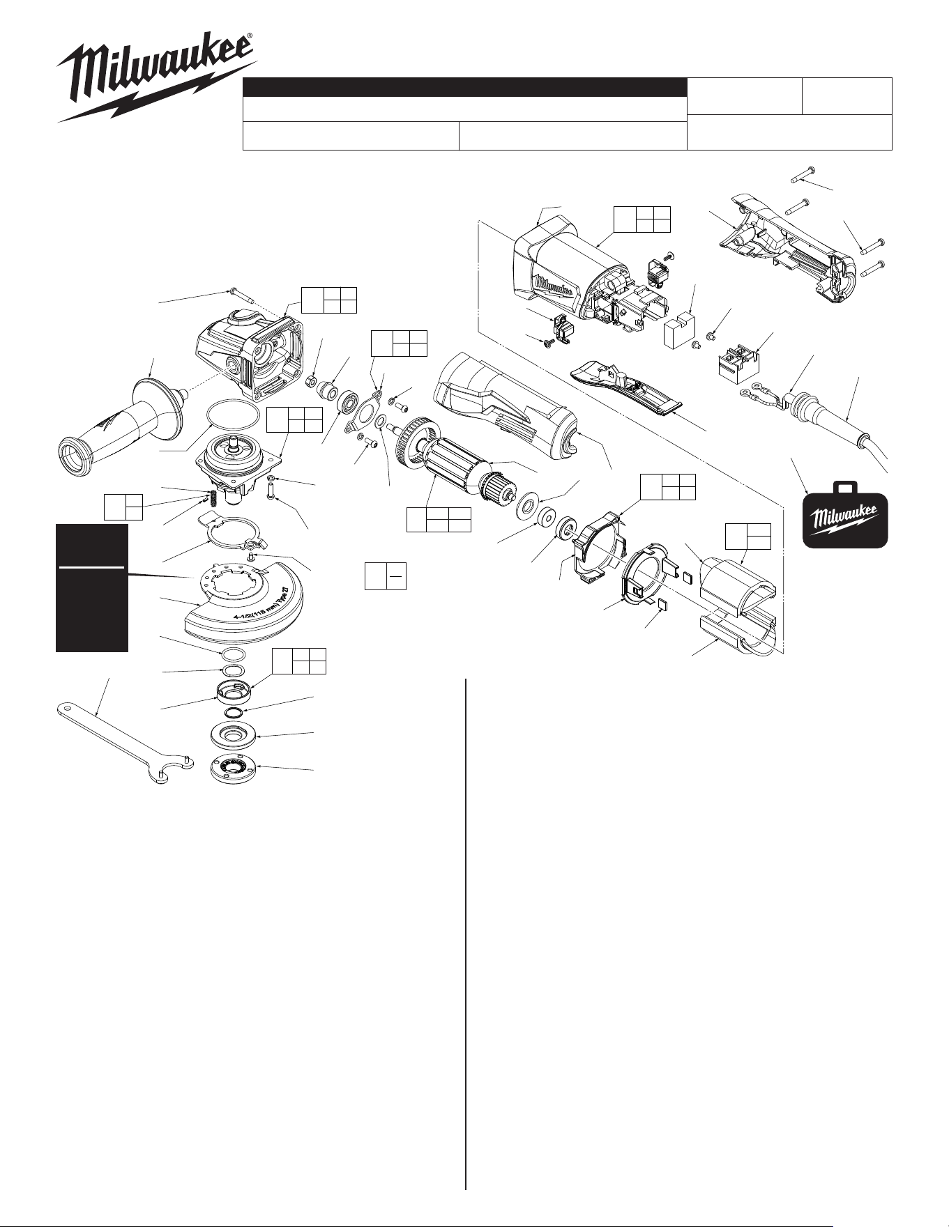
FIG. PART NO. DESCRIPTION OF PART NO. REQ.
41 --------------- BaeFoot (1)
42 --------------- Bae (1)
43 42-96-0405 RubberBearingCap (1)
44 16-10-0850 ArmatureAssembly (1)
44a 02-04-2110 BallBearing (1)
44b 31-86-0090 PlasticDisc (1)
44c --------------- Armature (1)
44d 45-88-0406 Washer (1)
45 05-78-0105 M4x10mmPanHd.Tapt.T-20Screw (2)
46 44-86-0155 BearingRetainer (1)
47 --------------- Pinion (1)
48 05-55-0620 M5HexNut (1)
49 12-20-6142 ServiceNameplate(NotShown) (1)
50 10-20-6142 WarningLabel(NotShown) (1)
53 05-78-0305 M3.5x7mmPanHd.PhillipsScrew (2)
60 42-14-0520 BaeAssembly (1)
61 44-86-0145 BearingRetainingPlateAssembly (1)
62 14-46-6105 FlangewithRampsAssembly (1)
65 14-46-0241 Spring/PinKit (1)
66 31-50-6140 Handle/MotorHousingServiceKit (1)
68 31-92-0210 PaddleTriggerAssembly (1)
70 42-55-6148 CanvasToolBag(Optional) (1)
FIG. PART NO. DESCRIPTION OF PART NO. REQ.
1 05-88-1650 M4x25mmPanHd.STScrewT-20 (4)
2 42-62-0120 SideHandleAssembly (1)
3 14-30-0083 GearCaseAssembly (1)
3g 02-04-0620 BallBearing (1)
4 34-40-0180 O-Ring (1)
5 14-73-0462 SpindleHubAssembly (1)
5d --------------- SteelPin (1)
FIG. PART NO. DESCRIPTION OF PART NO. REQ.
5f --------------- Spring (1)
5g 44-20-0155 GuardLockingTang (1)
5h 05-81-0020 M3x5mmPanHd.STT-8Screw (1)
6 05-90-0225 SpringWasher (6)
7 05-78-5316 M4x14mmPanHd.Tapt.T-20Screw (4)
8 43-54-1200 4.5"Type27Guard(StandardEquip.) (1)
9 --------------- O-Ring (1)
10 --------------- WaveySpring (1)
11 --------------- FlangewithRamps (1)
12 --------------- RetainingRing (1)
13 43-34-0935 InnerDiscFlange (1)
15 44-40-0035 OuterFlangeNut (1)
16 49-96-7215 SpannerWrench (1)
21 05-88-1300 M4x28mmPanHd.STT-20Screw (2)
22 05-88-1200 M4x16mmPanHd.STT-20Screw (2)
23 44-76-0095 CordProtector (1)
24 22-64-2021 PowerCord (1)
27 23-66-0185 On-OSwitch (1)
32 22-18-2240 CarbonBrushAssembly(Setof2) (1)
33 05-88-0030 M3x8.5mmPanHd.STT-10Screw (2)
34 --------------- MotorHousing (1)
35 23-16-0075 FoamBlock (1)
36 --------------- HandleSupport,LeftHandleHalve (1)
38 --------------- HandleCover,RightHandleHalve (1)
39 18-07-0280 FieldAssembly (1)
39a --------------- FieldHalve (1)
39b --------------- FieldHalve (1)
40 42-28-0085 RubberBlock (2)
MILWAUKEE TOOL ● www.milwaukeetool.com
13135W.LisbonRoad,Brookeld,WI53005
Drwg.3
6141-31
54-38-2312
H39C
4.5" COMPACT ANGLE GRINDER with PADDLE SWITCH
REVISEDBULLETIN
54-38-2311
DATE
Aug.2022
SERVICE PARTS LIST
BULLETIN NO.
WIRINGINSTRUCTION
CAT. NO.
SPECIFY CATALOG NO. AND SERIAL NO. WHEN ORDERING PARTS
STARTING
SERIALNUMBER
See Reverse Side
FIG. LUBRICATION
Use Type 'Y' Grease, No. 49-08-5270
3,5,47 WhenservicingtheGearCaseAssembly(3),Pinion(47)or
theSpindleHubAssembly(5):
90-95%oftheoldgreasemustberemovedpriortoanynew
greasebeingadded.Besurethatallgearteethareheavily
coatedwhenreassembling.
EXAMPLE:
ComponentParts(Small#)
AreIncludedWhenOrdering
TheAssembly(Large#).
0
00
Type 27
Guard is
Std. Equip.
Optional
Type 1
Guard
available.
Order No.
43-54-1210.
«
«
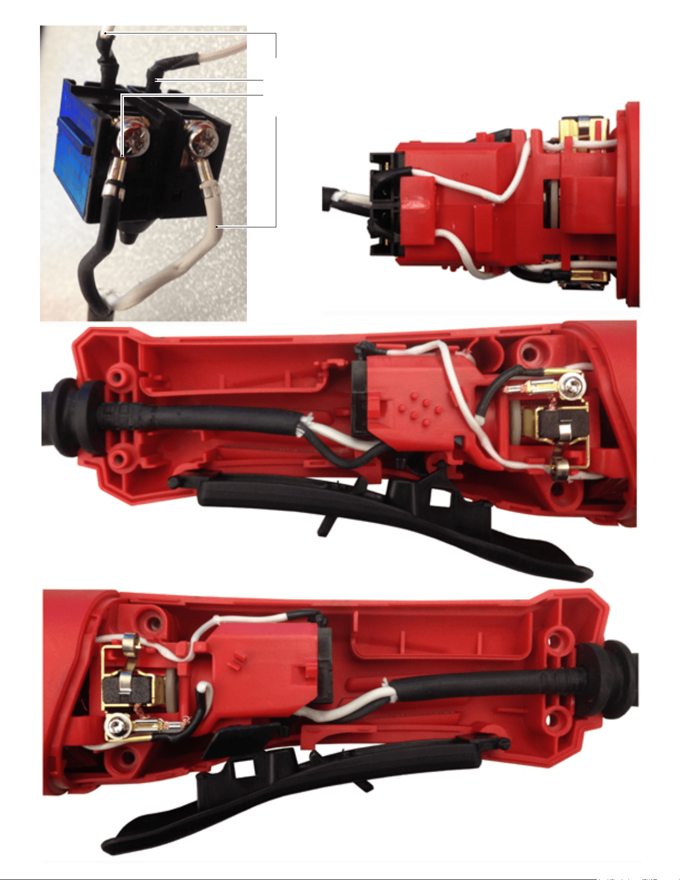
TOP VIEW
HANDLE SUPPORT (Left Handle Halve)
Install all components and route wires here before
securing with Handle Cover.
HANDLE COVER (Right Handle Halve)
(6141-30 shown with Lock Button)
6141-31 does not have the Lock Button feature
Route and trap wires as shown in the illustrations
below. Be sure to place all components firmly and
squarely in handle halve cavities. Be sure the wires
are pushed to the bottom of wire traps. Check for any
interferences prior to installing the handle cover.
Check for proper switch and lock movement before
activating the tool.
White from bottom right Field
White from top left Field
Black from Power Cord
White from Power Cord