
MILWAUKEE ELECTRIC TOOL CORPORATION
13135 W. Lisbon Road, Brookeld, WI 53005
Drwg. 4
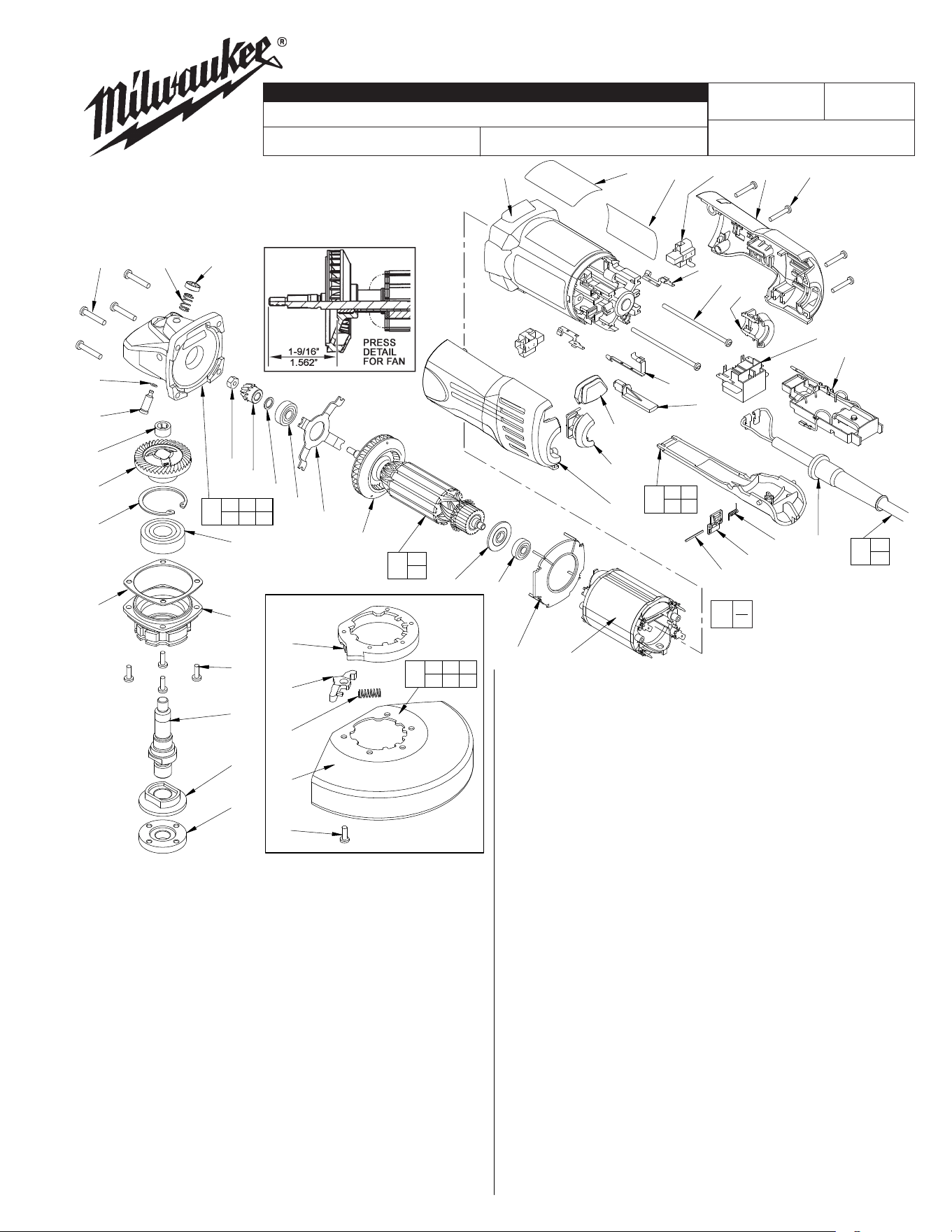
FIG. PART NO. DESCRIPTION OF PART NO. REQ.
6 06-82-5316 8-32 x .50 Taptite T-20 Screw (4)
7 06-82-7271 6-19 x .875 Slotted Plastite T-15 (4)
8 06-82-7326 8-16 x 1.00 Slotted Plastite T-20 (4)
9 06-82-7421 6-19 x 3.25 Slotted Plastite T-15 (2)
10 10-98-7095 Warning Label (1)
11 12-99-1990 Service Nameplate Kit (1)
12 14-20-3105 Electronics Assembly (1)
13 16-10-2010 Armature (1)
14 18-10-2005 Field (1)
15 22-20-1010 Brush Holder Assembly (Incl. Brushes) (2)
16 22-64-0845 Cord Set Assembly (1)
17 23-27-0106 Magnet Assembly (1)
18 23-66-2401 Switch (1)
19 23-74-1201 Switch Terminal (1)
20 23-74-1206 Brush Terminal (2)
21 28-14-0705 Gear Case Assembly (1)
22 28-53-0160 Spindle Hub (1)
23 31-12-0205 Cap (1)
24 31-17-0260 Cord Clamp - Left (1)
25 31-17-0265 Cord Clamp - Right (1)
26 31-44-0660 Handle Half - Right (1)
27 31-44-0665 Handle Half - Left (1)
28 31-50-1135 Motor Housing (1)
29 31-53-0080 Plug (1)
30 31-53-0150 Dial Opening Plug (1)
31 31-92-0320 Paddle Assembly (1)
6160-20
54-38-0425
A16A
6" ANGLE GRINDER
REVISED BULLETIN
DATE
Nov. 2005
SERVICE PARTS LIST
BULLETIN NO.
WIRING INSTRUCTION
CATALOG NO.
SPECIFY CATALOG NO. AND SERIAL NO. WHEN ORDERING PARTS
STARTING
SERIAL NUMBER
FIG. PART NO. DESCRIPTION OF PART NO. REQ.
32 32-05-1310 Spiral Bevel Gear (1)
33 32-60-1310 Spiral Bevel Pinion (1)
34 34-40-4300 O-Ring (1)
35 34-80-2960 Retaining Ring - Internal Bevel (1)
36 38-50-5212 Spindle (1)
37 40-50-8650 Compression Spring (1)
38 42-14-0400 Bafe (1)
39 44-60-0845 Lock Pin (1)
40 44-66-5345 Bearing Retainer Plate (1)
41 45-14-0280 Pinion Shim (1)
42 49-05-0110 Flange Nut (1)
43 49-05-0125 Back Flange (1)
44 22-84-0960 Fan Assembly (1)
45 06-65-1915 Pin (1)
46 42-42-0390 Lock-Off Button (1)
47 40-50-8750 Torsion Spring (1)
48 44-76-0210 Cord Protector (1)
49 45-36-1620 Spacer (1)
50 44-20-0610 Guard Lever (1)
51 40-50-1555 Compression Spring (1)
52 28-41-1055 6" Guard Hood (1)
53 06-82-7409 8-16 x .50 Slotted Plastite T-20 (5)
54 49-12-0300 6" Type 27 Guard (1)
56 43-44-1080 Gasket (1)
49-15-0310 Side Handle (1)
49-96-7205 Spanner Wrench (1)
FIG. LUBRICATION:
21 9-12 Grams Type "Y" Grease, No. 49-08-5270.
32,33 Type "Y" Grease, No. 49-08-5270, Must Be Applied
To All Gear Teeth.
FIG. NOTES:
4 Press .09" Below Casting Surface, Lettering Side Out.
5 Torque To 25-35 In./Lbs.
22 Position The Spindle Hub With The Side That Has The
Word "Back" Orientated Toward The Rear Of The Tool.
FIG. PART NO. DESCRIPTION OF PART NO. REQ.
1 02-04-0852 Ball Bearing (1)
2 02-04-1745 Ball Bearing (1)
3 02-04-2080 Ball Bearing (1)
4 02-50-2423 Needle Bearing (1)
5 06-55-3850 Hex Nut (1)
EXAMPLE:
Component Parts (Small #)
Are Included When Ordering
The Assembly (Large #).
0
0
0
See Reverse Side
34
37
8
11
10
28
15
7
26
20
9
25
18
12
19
29
30
24
27
45
46
47
48
42
43
36
6
22
2
39
4
32
35
41
40
17
3
38
14
1
33
5
23
4 5 4 6
4 7
31
4 8
16
4 2 3 3 4
3 7 3 9
21
4 9 5 0 5 1
5 2 5 3
54
1 7
4 4
13
56
44
53
49
50
51
52
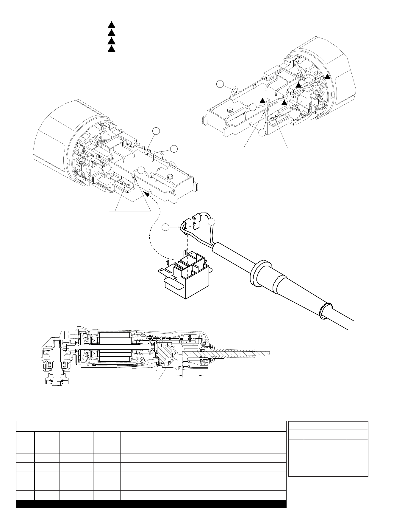
TUCK CORD LEADS #1 AND #2
AWAY FROM VENT OPENINGS.
INSERT WHITE LEADWIRE #3
INTO THE WIRE TRAP AND
CONNECT TO THE SWITCH
TERMINAL.
INSERT BLACK LEADWIRE #4
INTO THE WIRE TRAP AND
CONNECT TO THE SWITCH
TERMINAL.
BLUE LEADWIRE #5 CONNECTION:
ROUTE THROUGH THE WHITE LEADWIRE #3 LOOP.
ROUTE THROUGH THE POTTING SHELL POSTS.
ROUTE ALONG THE GROOVE IN THE MOTOR HOUSING.
CONNECT THE WIRE TERMINAL TO THE FIELD TERMINAL.
1
2
3
4
BLACK LEADWIRE #1 AND WHITE LEAD-
WIRE #2 ARE INTERCHANGEABLE
ON THE SWITCH CONNECTIONS.
.50±
.25
WIRING SPECIFICATIONS
Terminals, Connectors and 1 or 2 End Wire Preparation
Wire
Color
Origin or
Gauge
Wire
No.
Length
TERMINAL DESCRIP-
Part No.Code Qnty.
1 Black 22-64-0845 2.75 Component of the cord set.
2 White 22-64-0845 2.75 Component of the cord set.
3 White 14-20-3105 2.00 Component of the electronics assembly.
4 Black 14-20-3105 2.13 Component of the electronics assembly.
5 Blue 14-20-3105 4.00 Component of the electronics assembly.
BULK LEAD WIRE - BULLETIN NO. 58-01-0003
.00
3
WHITE
5
BLUE
4
BLACK
2
1
BLACK
WHITE
3
WHITE
5
BLUE
4
BLACK
2
1
3
4