deutsch / english
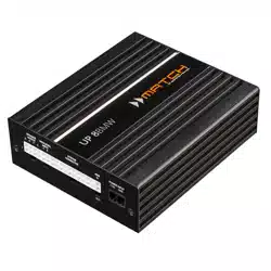
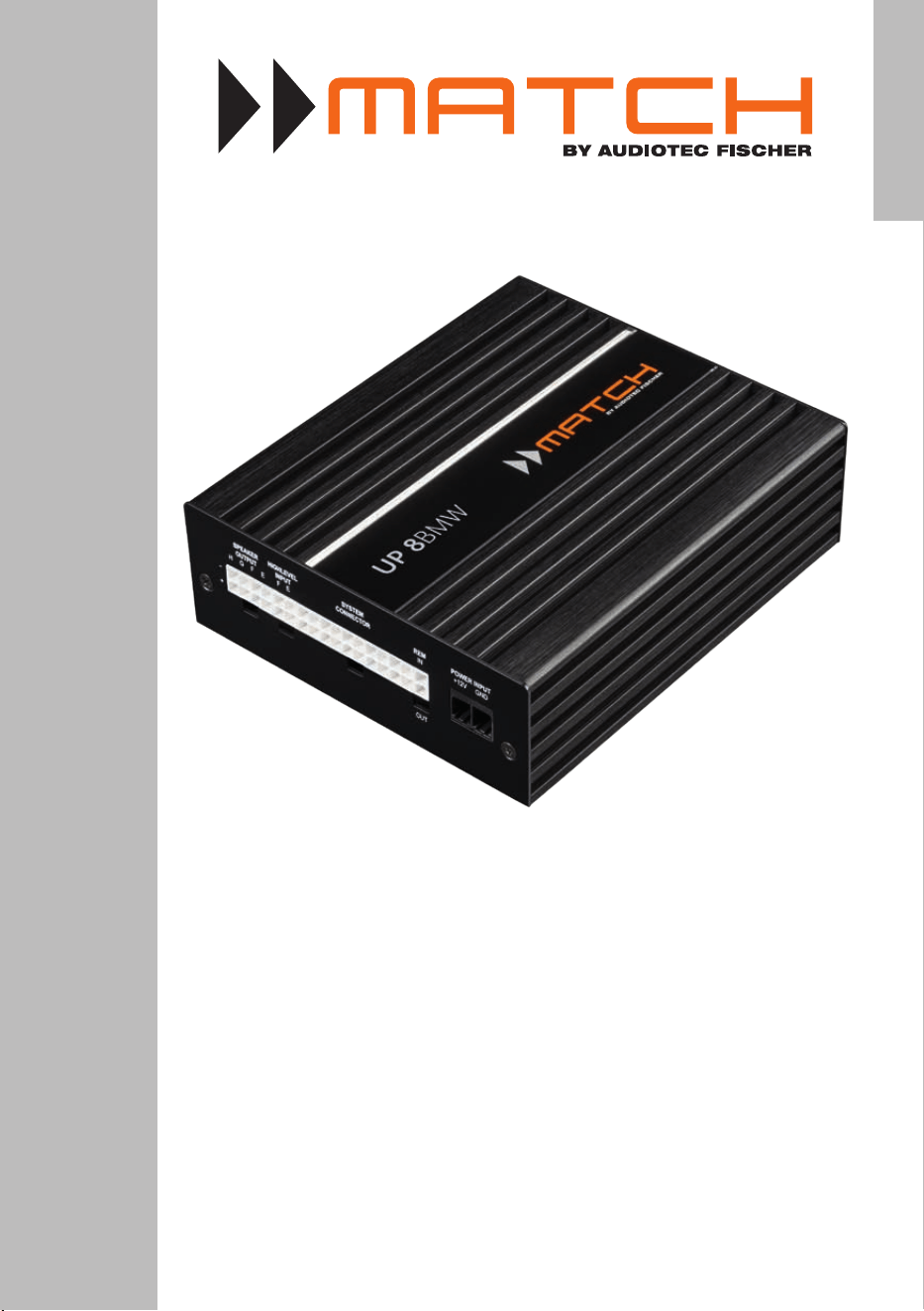
UP 8BMW
UPGRADE
Plug & Play DSP-Verstärker für BMW E & F Modelle
mit HiFi-Soundsystem (Option 676)
Plug & Play DSP amplier for BMW E & F models with
HiFi sound system (option 676)

Sehr geehrter Kunde,
wir gratulieren Ihnen zum Kauf dieses hochwertigen
MATCH Verstärkers mit integriertem DSP.
MATCH setzt mit dem UP 8BMW neue Maßstäbe im
Bereich der Verstärkertechnik. Dabei protieren Sie
als Kunde direkt von unserer mehr als 30-jährigen
Erfahrung in der Forschung und Entwicklung von
Audiokomponenten.
Dieser Upgrade-Verstärker wurde von uns nach
neuesten technischen Erkenntnissen entwickelt und
zeichnet sich durch hervorragende Verarbeitung
und eine überzeugende Anwendung ausgereifter
Technologien aus.
Viel Freude an diesem Produkt wünscht Ihnen das
Team von
AUDIOTEC FISCHER
Herzlichen Glückwunsch!
Allgemeine Hinweise
Allgemeines zum Einbau von MATCH-Kompo-
nenten
Um alle Möglichkeiten des Produktes optimal aus-
schöpfen zu können, lesen Sie bitte sorgfältig die
nachfolgenden Installationshinweise. Wir garantie-
ren, dass jedes Gerät vor Versand auf seinen ein-
wandfreien Zustand überprüft wurde.
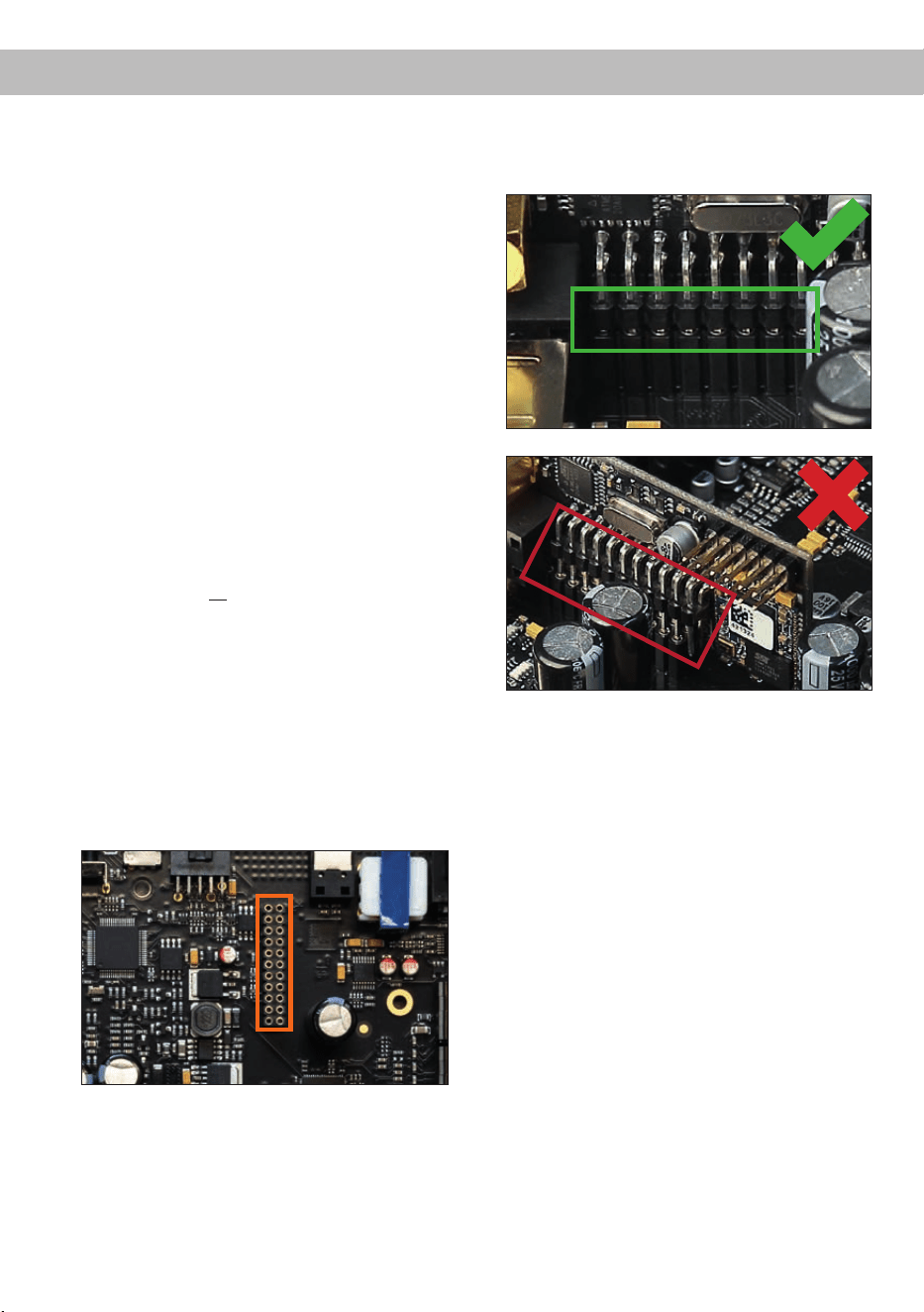
Vor Beginn der Installation unterbrechen Sie
den Minusanschluss der Autobatterie.
Installieren Sie Ihren UP 8BMW Verstärker aus-
schließlich mit der beiliegenden Montageplatte am
ursprünglichen Einbauplatz des zu ersetzenden
Original-Verstärkers.
Wir empfehlen Ihnen, die Installation von einem
Einbauspezialisten vornehmen zu lassen, da der
Nachweis eines fachgerechten Einbaus und An-
schlusses des Gerätes Voraussetzung für die
Garantieleistungen ist.
Allgemeines zum Anschluss des UP 8BMW
Verstärkers
Der Verstärker darf nur in Kraftfahrzeuge eingebaut
werden, die den 12 V-Minuspol an Masse haben.
Bei anderen Systemen können der MATCH Ver-
stärker und die elektrische Anlage des Kfz beschä-
digt werden. Nur bei direkter Spannungsversor-
gung über den Power Input (Seite 7, Punkt 4): Die
Plusleitung für die gesamte Anlage sollte in einem
Abstand von max. 30 cm von der Batterie mit ei-
ner Hauptsicherung abgesichert werden. Der Wert
der Sicherung errechnet sich aus der maximalen
Stromaufnahme der Car-Hi Anlage.
Verwenden Sie zur Verbindung des MATCH
UP 8BMW Verstärkers mit dem werkseitigen
Kabelbaum ausschließlich das beiliegende
MATCH-Anschlusskabel! Die Verwendung eines
anderen Kabels kann zu Schäden an ihrer Anla-
ge führen. Die Sicherung im Verstärker dürfen
nur mit dem gleichen Wert (25 A) ersetzt wer-
den, um eine Beschädigung des Gerätes zu ver-
hindern. Höhere Werte können zu gefährlichen
Folgeschäden führen!
Die Kabelverbindungen müssen so verlegt sein,
dass keine Klemm-, Quetsch- oder Bruchgefahr be-
steht. Bei scharfen Kanten (Blechdurchführungen)
müssen alle Kabel gegen Durchscheuern gepols-
tert sein. Ferner darf das Versorgungskabel niemals
mit Zuleitungen zu Vorrichtungen des Kfz (Lüfter-
motoren, Brandkontrollmodulen, Benzinleitungen
etc.) verlegt werden.
3
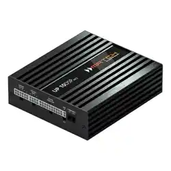
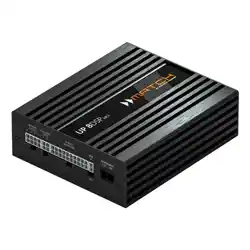
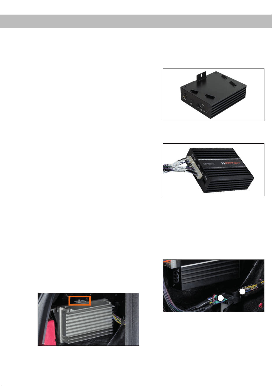
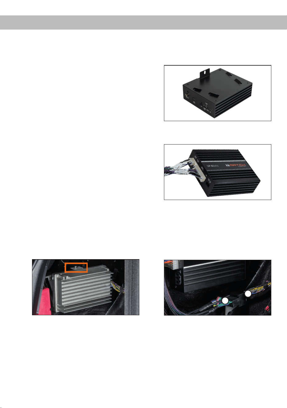
deAnschluss- und Bedienelemente
1 2 3 4 5
1
Lautsprecherausgänge E - H
Seite 6, Punkt 2
2
Highlevel-Lautsprechereingäge E & F
Unbenutzt bei BMW HiFi Soundupgrade
3
System Connector Eingang
Seite 6, Punkt 2
4
Remote-Anschlüsse
Seite 6, Punkt 2
5
Optional: Anschluss Stromversorgung
Seite 7, Punkt 4
6
USB Eingang
Seite 7, Punkt 5
7
Control Taster
Seite 10, Punkt 2
8
Auto Remote-Schalter
Seite 6, Punkt 3
9
SCP (Smart Control Port)
Seite 10, Punkt 3
10
Optischer Digitaleingang
Unbenutzt bei BMW HiFi Soundupgrade
11
Vorverstärkerausgang
Unbenutzt bei BMW HiFi Soundupgrade
12
Status LED
Seite 10, Punkt 1
6 7 8 9 10 11
12
4
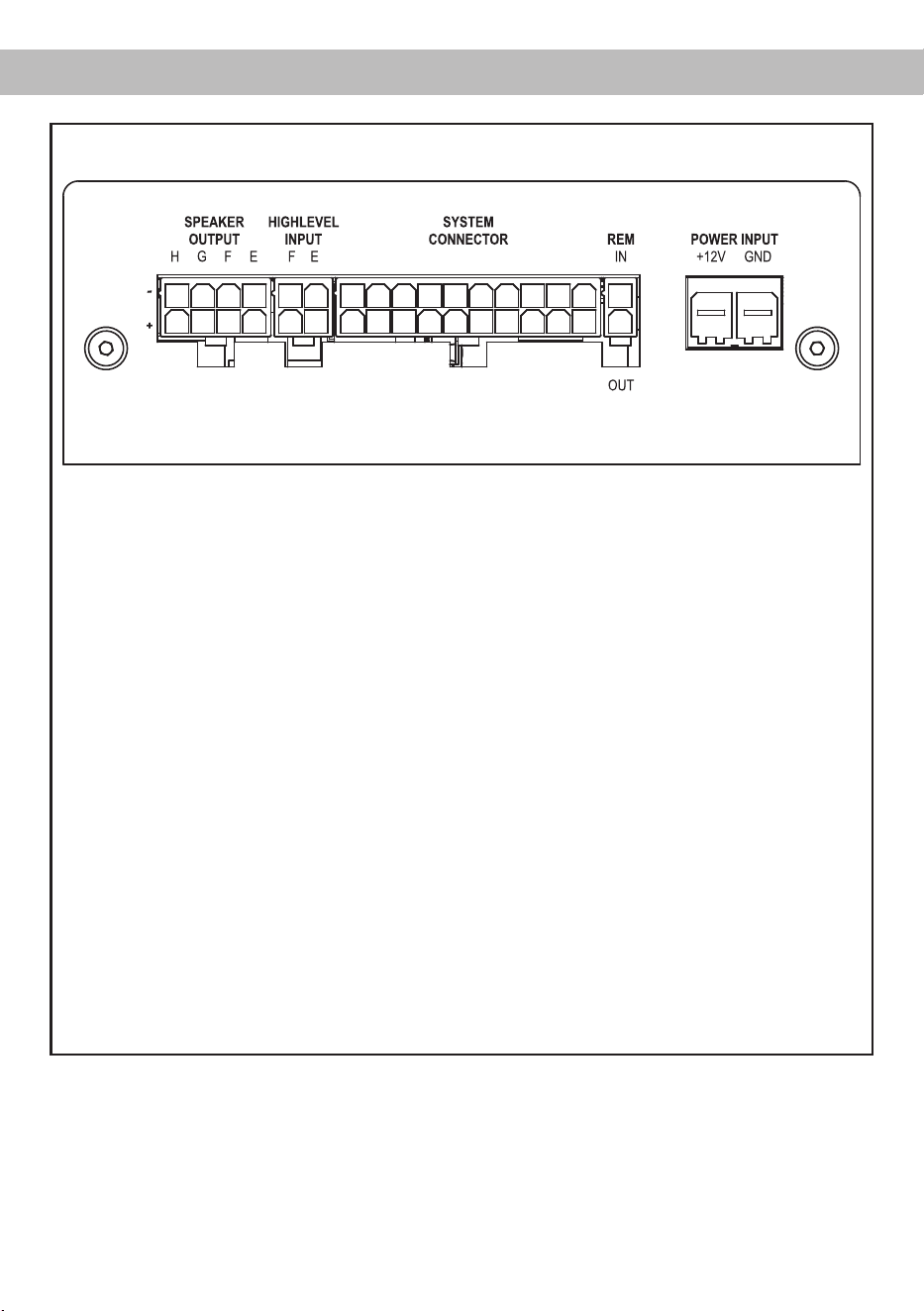
Abb. 1: Pinbelegung UP 8BMW
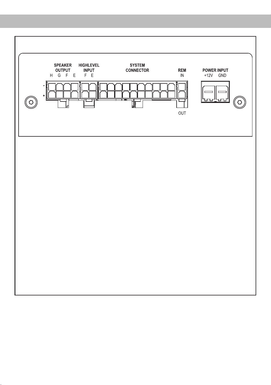
System Connector
1. Highlevel-Lautsprechereingang hinten links (-) / C
2. Highlevel-Lautsprechereingang vorne links (-) / A
3. Highlevel-Lautsprechereingang vorne rechts (-) / B
4. Highlevel-Lautsprechereingang hinten rechts (-) / D
5. Lautsprecherausgang hinten rechts (-) / D
6. Lautsprecherausgang hinten links (-) / C
7. Lautsprecherausgang vorne rechts (-) / B
8. Lautsprecherausgang vorne links (-) / A
9. Masse
10. Masse
11. Highlevel-Lautsprechereingang hinten links (+) / C
12. Highlevel-Lautsprechereingang vorne links (+) / A
13. Highlevel-Lautsprechereingang vorne rechts (+) / B
14. Highlevel-Lautsprechereingang hinten rechts (+) / D
15. Lautsprecherausgang hinten rechts (+) / D
16. Lautsprecherausgang hinten links (+) / C
17. Lautsprecherausgang vorne rechts (+) / B
18. Lautsprecherausgang vorne links (+) / A
19. +12 Volt
20. +12 Volt
Speaker Output E - H
25. Subwooferausgang rechts (-) / H
26. Subwooferausgang links (-) / G
27. Unbenutzt bei BMW HiFi Soundupgrade
28. Centerausgang (-) / E
29. Subwooferausgang rechts (+) / H
30. Subwooferausgang links (+) / G
31. Unbenutzt bei BMW HiFi Soundupgrade
32. Centerausgang (+) / E
28272625
2019181716151413121132313029 2423
2221 10987654321
Hardware-Konguration
Highlevel Input E - F
21. Unbenutzt bei BMW HiFi Soundupgrade
22. Unbenutzt bei BMW HiFi Soundupgrade
21. Unbenutzt bei BMW HiFi Soundupgrade
21. Unbenutzt bei BMW HiFi Soundupgrade
34
33
REM IN / OUT
33. Remote-Eingang 34. Unbenutzt
bei BMW HiFi Soundupgrade

5
de
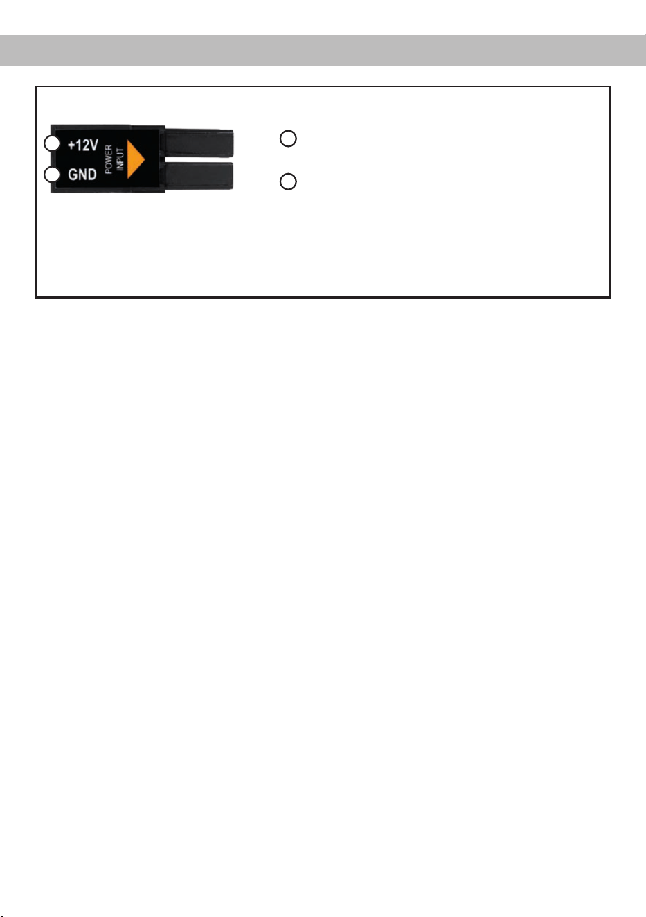
Abb. 2: Belegung Power Input Stecker
Steckeroberseite
A
+12 V – Zum Anschluss des +12 V Versorgungskabels.
B
GND – Zum Anschluss des Massekabels.
A
B
ACHTUNG: Der Power Input darf niemals gleichzeitig mit der Spannungsversorgung am System Con-
nector / Plug & Play Kabelbaum verwendet werden. Sofern die Spannungsversorgung am Power Input
genutzt wird, ist es zwingend erforderlich Hardwarekongurationen im Verstärker vorzunehmen (siehe
Seite 7, Punkt 4).
6
Montieren und kongurieren Sie den MATCH
UP 8BMW in der nachfolgenden Reihenfolge
Achtung: Für die Durchführung der nachfolgenden
Schritte werden Spezialwerkzeuge und Fachwissen
benötigt. Um Anschlussfehler und Beschädigungen
zu vermeiden, fragen Sie im Zweifelsfall Ihren Ein-
bauspezialisten und beachten Sie zwingend die
allgemeinen Anschluss- und Einbauhinweise (siehe
Seite 2).
1. Ausbau des Original-Verstärkers
a. Entfernen Sie vorsichtig die Verkleidung,
hinter der sich der Original-Verstärker ben-
det. In den meisten Fällen ist dies die linke
Seitenverkleidung im Koerraum.
Hinweis: Die Verkleidungen können an be-
stimmten Stellen mit verdeckten Schrauben
am Karosserieblech befestigt sein. Verge-
wissern Sie sich, dass Sie alle Schrauben
gelöst haben, bevor Sie die Verkleidung
abnehmen. Zusätzlich ist die Verkleidung
meist mit Halteclips befestigt. Achten Sie
beim Lösen der Verkleidung darauf, dass Sie
diese vorsichtig entfernen und dabei nicht
zerstören. Die Umgebungstemperatur beim
Entfernen der Clips sollte mindestens 10° C
betragen.
b. Ziehen Sie alle Steckverbindungen vom
Original-Verstärker ab.
c. Lösen Sie die Verschraubung zwischen dem
Montageblech des Verstärkers und der Ori-
ginal-Aufnahme der Fahrzeugkarosserie (Je
nach Modell kann es notwendig sein zuvor
auch die Original-Aufnahme zu demontie-
ren). Anschließend ziehen Sie den Original-
Verstärker je nach Modell zur Seite oder
nach oben hin ab.
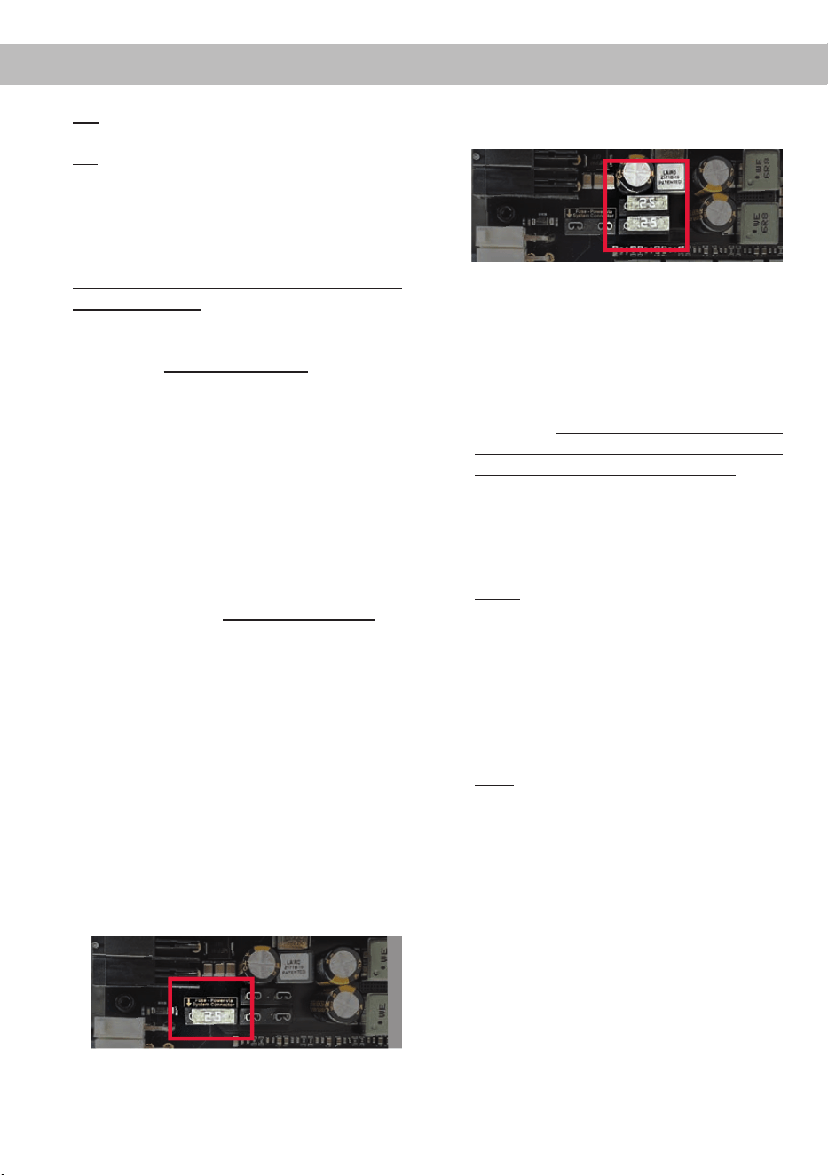
2. Montage des UP 8BMW Verstärkers
a. Befestigen Sie das mitgelieferte Monta-
geblech mit den im Lieferumfang bend-
lichen Senkkofpschrauben auf der Untersei-
te des Verstärkers.
b. Verbinden Sie die Stecker des MATCH An-
schlusskabels mit dem Verstärker (System
Connector, Speaker Output E - H und REM).
c. Schieben Sie den Verstärker samt Monta-
geblech auf die Original-Befestigungsplatte
im Fahrzeug.
d. Verschrauben Sie anschließend das Monta-
geblech wieder mit der Original-Aufnahme
im Fahrzeug.
e. Zuletzt verbinden Sie die Kupplung des
UP 8BMW Anschlusskabels (1) mit dem Ste-
cker des Fahrzeugkabelbaums (2).
1
2
3. Konguration des Remote-Eingangs
Sofern die UP 8BMW den Verstärker des BMW
HiFi-Soundsystems (676) ersetzt erfolgt die
Einschaltung des Verstärkers über das Remo-
te-Kabel des beiliegenden Kabelbaums. Der
Auto Remote-Schalter muss dabei auf „O“ ge-
stellt werden.
Hardware-Konguration
7
de
On: Einschaltung über Highlevel-Lautspreche-
reingänge.
O: Einschaltung über Remote-Signal
(Werkseinstellung).
4. Optional: Anschluss der Stromversorgung
Beim BMW HiFi Soundupgrade wird die
UP 8BMW über den beiliegenden Kabelbaum
direkt vom Original-Kabelbaum des Fahrzeugs
mit Strom versorgt.
Eine direkte Stromversorgung über die Fahr-
zeugbatterie kann notwendig sein, wenn:
- die UP 8BMW außerhalb der Standardan-
wendung als BMW HiFi Soundupgrade ge-
nutzt wird
- leistungsstärkere Laut sprecher (bspw.
3 Ω HELIX COMPOSE Lautsprecher) ange-
schlossen werden oder
- leistungsstärkere Subwoofer (bspw. 2 Ω
MATCH UPGRADE Subwoofer oder 2 Ω
HELIX COMPOSE Lautsprecher) ange-
schlossen werden.
In diesem Fall ist es zwingend erforderlich zu-
vor die nachfolgende Hardwarekonguration im
inneren des Verstärkers vorzunehmen.
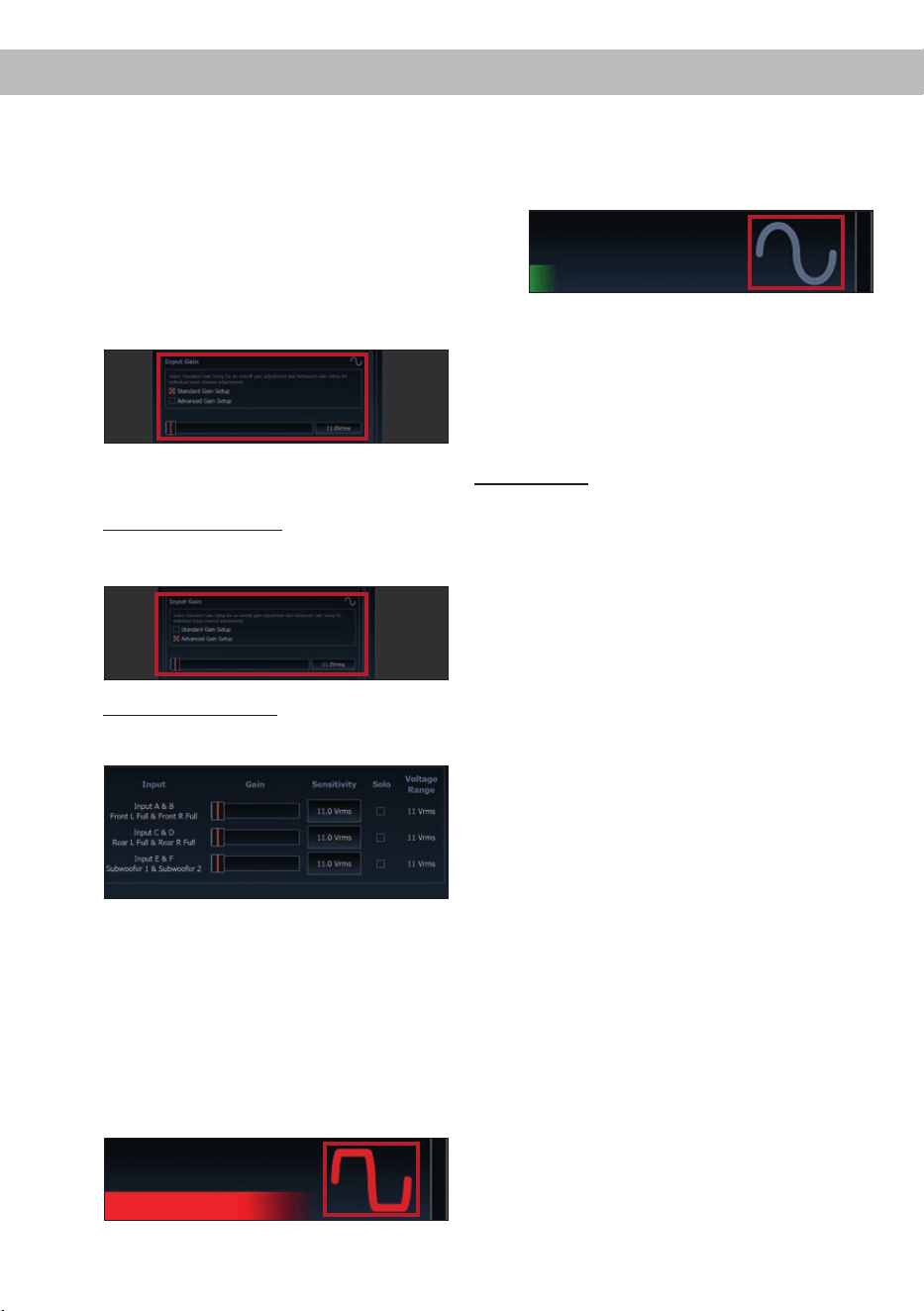
a. Montageblech entfernen und Verstärker
önen
Demontieren Sie das Montageblech des Ver-
stärkers, indem Sie die vier Senkkopfschrau-
ben lösen. Anschließend entfernen Sie das
Seitenblech mit dem „System Connector“-
Eingang indem Sie die zwei Kreuzschlitz-
schrauben lösen und ziehen das Bodenblech
zur Seite heraus.
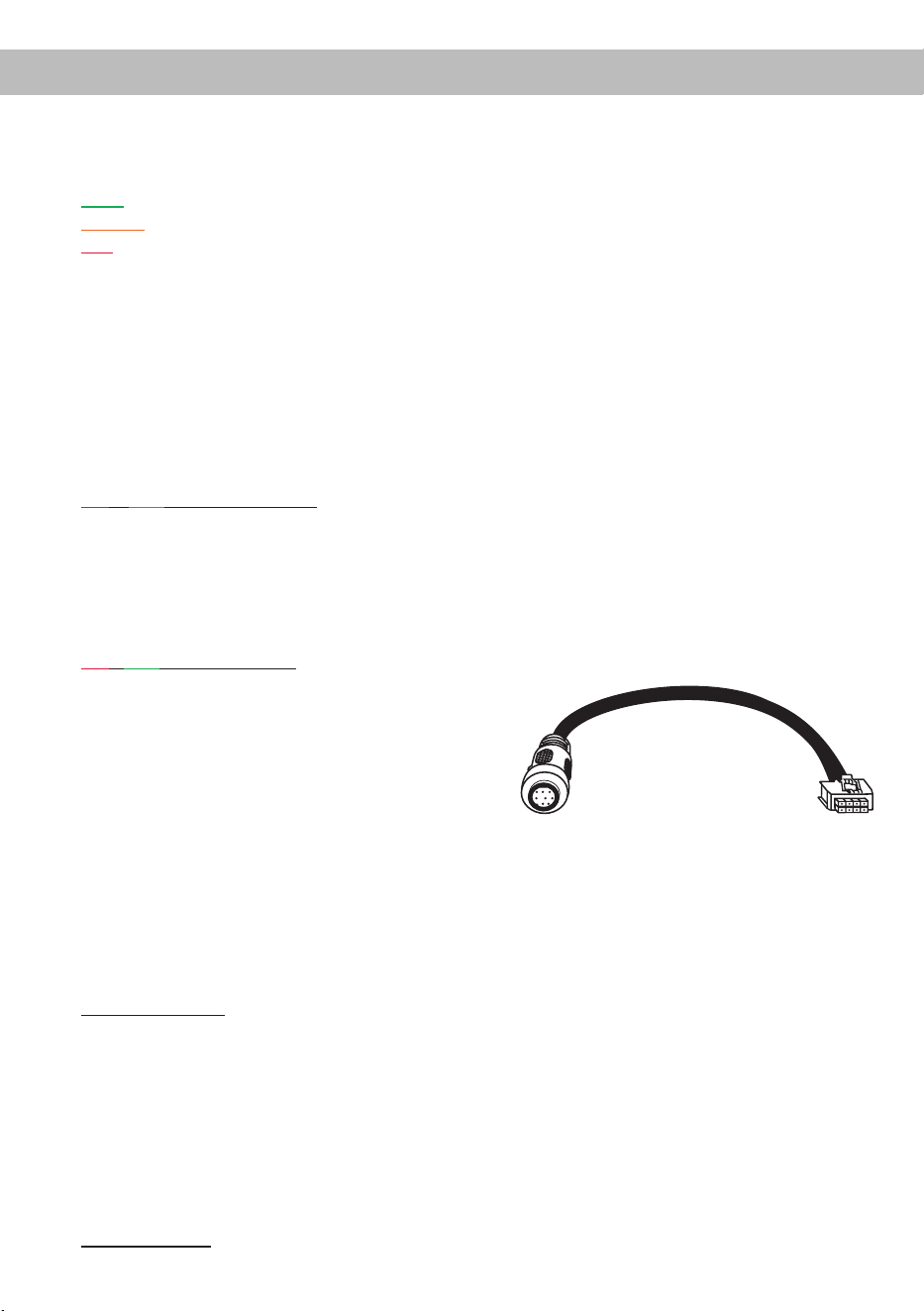
b. Sicherung entfernen
Entfernen Sie die markierte 25 A Sicherung
indem Sie diese einfach nach oben heraus-
ziehen.
c. Zwei Sicherungen stecken
Stecken Sie die zuvor entfernte 25 A Siche-
rung und die im Lieferumfang enthaltene
25 A Sicherung auf die im nachfolgenden Bild
markierten Steckplätze.
d. Verstärker zusammenbauen und Monta-
geblech montieren
Setzen Sie den Verstärker wie zuvor be-
schrieben in umgekehrter Reihenfolge wie-
der zusammen
e. Stromversorgung am Power Input an-
schließen
WICHTIG: Vor dem Anschluss des +12 V
Versorgungskabels an das Bordnetz muss
die Autobatterie abgeklemmt werden.
Schließen Sie die Stromversorgung aus-
schließlich über den mitgelieferten Power
Input Stecker (siehe Seite 5, Abb. 2) an.
Achten Sie unbedingt auf eine korrekte Po-
larität.
+12 V: Das +12 V Stromkabel ist am Pluspol
der Batterie anzuschließen. Die Plusleitung
sollte in einem Abstand von max. 30 cm von
der Batterie mit einer Hauptsicherung (50 A)
abgesichert werden. Verwenden Sie bei
kurzen Leitungen (< 1 m) einen Querschnitt
von mindestens 6 mm². Bei längeren Lei-
tungen empfehlen wir einen Querschnitt von
10 mm² bis 16 mm².
GND: Anschluss für die Masseleitung. Das
Massekabel muss an einer nicht isolierten
Stelle mit dem Kfz-Chassis verbunden wer-
den. Der Kabelquerschnitt sollte den glei-
chen Durchmesser wie die Plusleitung ha-
ben. Ein nicht ausreichender Massekontakt
führt zu unerwünschten Störgeräuschen und
Fehlfunktionen.
5. Anschluss an den Computer & Einschalten
Mit Hilfe des USB Eingangs kann die UP 8BMW
über das beiliegende Kabel mit dem Com-
puter verbunden und anschließend über das
DSP PC-Tool konguriert werden.
Hinweis: Es können keine USB Speichermedien
an den Verstärker angeschlossen werden.
Bevor Sie die UP 8BMW das erste Mal an einen

8
Computer anschließen, gehen Sie auf unsere
Homepage und laden die aktuellste Software
Version des DSP PC-Tools herunter. Es ist rat-
sam, vor der Programmierung des DSPs nach
Updates der Software zu schauen, damit das
Gerät immer auf dem aktuellsten Stand ist.
Die Software sowie eine umfang-
reiche Knowledge Base nden Sie auf
www.audiotec-scher.com.
Es wird dringend empfohlen, die DSP PC-Tool
Knowledge Base vor der ersten Benutzung
durchzulesen, um Komplikationen und Fehler
zu vermeiden.
Wichtig: Stellen Sie sicher, dass der Verstärker
bei der ersten Installation der Software noch
nicht am PC angeschlossen ist. Verbinden Sie
diesen erst, wenn die Software samt der USB-
Treiber vollständig installiert ist.
Im folgenden Abschnitt lesen Sie die wich-
tigsten Schritte zum Anschluss und der ersten
Inbetriebnahme:
a. Laden Sie die DSP PC-Tool Software unter
www.audiotec-scher.com herunter und
installieren diese auf ihrem Computer.
b. Schließen Sie danach den Verstärker mit
dem beiliegenden USB-Kabel an den Com-
puter an. Wenn Sie längere Distanzen zu
überbrücken haben, verwenden Sie bitte
eine aktive USB-Verlängerung mit integrier-
tem Repeater.
c. Schalten Sie erst die UP 8BMW ein und star-
ten Sie anschließend die Software. Sofern
die Betriebssoftware des Verstärkers nicht
mehr aktuell ist, wird diese automatisch ak-
tualisiert.
6. Konguration des internen DSPs
Es wird dringend empfohlen, vor der er-
sten Inbetriebnahme des Soundsystems die
grundlegenden Einstellungen im DSP mit
Hilfe der DSP PC-Tool Software vorzuneh-
men.
Nun können Sie mithilfe der DSP PC-Tool Soft-
ware ein fahrzeugspezisches Sound Setup auf
den Verstärker aufgespielen und nach eigenen
Bedürfnissen anpassen oder individuell kon-
gurieren.
Um ein fahrzeugspezisches Sound Setup auf
dem DSP des UP 8BMW Verstärkers zu instal-
lieren, gehen Sie wie folgt vor:
a.
Laden Sie sich auf der Seite
www.audiotec- scher.com ein fahr-
zeugspezisches Sound Setup herunter. Die
Datenbank nden Sie unter dem Menüpunkt
Tools → Sound Setups.
b. Anschließend wählen Sie das Gerät, den
Fahrzeughersteller und das Fahrzeugmodell
aus und können dann aus einer Liste das
Sound Setup des gewünschten Modells her-
unterladen.
c. Verbinden Sie nun die UP 8BMW, wie zuvor
beschrieben, mit Ihrem PC und starten die
DSP PC-Tool Software.
d. Laden Sie die zuvor heruntergeladene Sound
Setup-Datei in die DSP PC-Tool Software.
e. Optional können Sie nun das Sound Setup
mit der Software noch an Ihre Bedürfnisse
anpassen.
f. Wenn Sie alle Einstellungen vorgenommen
haben, speichern Sie das Sound Setup auf
dem DSP des UP 8BMW ab.
Nützliche Hinweise zu einer korrekten, indivi-
duellen Konguration entnehmen Sie unserer
Knowledge Base, welche auf unserer Webseite
bereit steht.
Achtung: Es wird dringend empfohlen, die
Lautstärke am Radio auf Minimum zu drehen
und die Signalausgänge zu muten. Speziell bei
Verwendung in vollaktiven Systemen besteht
sonst Zerstörungsgefahr für die Lautsprecher.
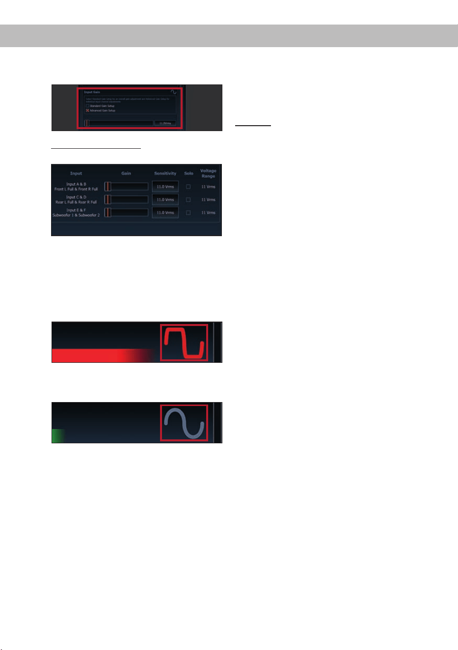
7. Einstellen der Eingangsempndlichkeit der
analogen Signaleingänge
ACHTUNG: Es ist zwingend notwendig, die
Eingangsempndlichkeit der UP 8BMW an
die Signalquelle anzupassen, um Schäden
am Verstärker zu vermeiden.
Mit Hilfe der DSP PC-Tool Software kann die
Eingangsempndlichkeit optimal an die Signal-
quelle angepasst werden.
Die Eingangsempndlichkeit ist für alle Kanäle
ab Werk auf 11 Volt eingestellt. Dies ist in nahe-
zu allen Fällen bereits die optimale Einstellung.
Nur wenn die Signalquelle einen zu kleinen
Max imalpegel liefert, sollte die Eingangsemp-
ndlichkeit vorsichtig angehoben werden.
Hardware-Konguration
9
de
Hinweis: Muten Sie während dieser Prozedur
die Signalausgänge der UP 8BMW.
Zur Anpassung der Eingangsempndlichkeit
führen Sie bitte die folgenden Schritte durch:
a. Schalten Sie den Verstärker ein.
b. Starten Sie die DSP PC-Tool Software.
c. Die Einstellung der Eingangsempndlichkeit
nden Sie im Tab „ Signalverwaltung“ des
DCM-Menüs unter dem Punkt „Main Input →
Input Gain“.
d. Wählen Sie das Setupverfahren zur Einstel-
lung der Eingangsempndlichkeit aus.
Standard Gain Setup: Hier kann die Ein-
gangsempndlichkeit global für alle Kanäle
eingestellt werden.
Advanced Gain Setup: Bei diesem Verfahren
ist eine individuelle Einstellung für die einzel-
nen Kanalpaare möglich.
e. Drehen Sie die Lautstärke Ihres Radios auf
90 % der Gesamtlautstärke und spielen Sie
ein geeignetes Testsignal, z.B. Rosa Rau-
schen, (Vollaussteuerung 0 dB) ab.
f. Sollte die Clipping Anzeige im DSP PC-Tool
bereits leuchten (siehe Markierung im fol-
genden Bild), verringern Sie mit Hilfe des
Schiebereglers die Eingangsempndlichkeit,
bis die Clipping Anzeige erlischt.
g. Erhöhen Sie die Eingangsempndlichkeit bis
die Clipping Anzeige aueuchtet. Schieben
Sie nun den Regler zurück bis die Clipping
Anzeige wieder erlischt.
8. Montage der Fahrzeugverkleidung
Wenn Sie die UP 8BMW ordnungsgemäß mon-
tiert und alle Einstellungen am Verstärker vor-
genommen haben, können sie die Verkleidung
wieder anbringen.
Warnhinweis:
Der UP 8BMW Verstärker hat eine höhere Lei-
stung als das Original-Autoradio bzw. der
Original-Verstärker. Die gängigen Original-
Lautsprecher werden, in Kombination mit den
richtigen DSP-Einstellungen, die Mehrleistung
des Verstärkers verkraften. Sollten jedoch eige-
ne DSP-Einstellungen vorgenommen werden,
kann es unter Umständen passieren, dass die
Original-Lautsprecher überlastet oder beschä-
digt werden. Wir empfehlen daher, gerade bei
hohen Lautstärken, immer darauf zu achten,
dass es zu keinem Zeitpunkt zu hörbaren Ver-
zerrungen in den Lautsprechern kommt, um Be-
schädigungen zu vermeiden.
Wichtig: Audiotec Fischer übernimmt keinerlei
Gewährleistung für eventuelle Schäden an den
werkseitig verbauten Lautsprechern, die durch
die Kombination mit der UP 8BMW entstanden
sind. Um Beschädigungen zu vermeiden, fragen
Sie im Zweifelsfall Ihren autorisierten MATCH Fach-
händler.
10
1. Status LED
Die Status LED zeigt den Betriebszustand des
Verstärkers und dessen Speichers an.
Grün: Verstärker eingeschaltet und betriebsbereit.
Orange: Power Save Modus aktiv.
Rot: Protection Mode aktiv. Dieser kann unter-
schiedliche Ursachen haben. Der Verstärker ist
mit Schutzschaltungen gegen Über- und Un-
terspannung sowie Überhitzung ausgestattet.
Prüfen Sie in diesem Fall alle Anschlüsse auf
Fehler, wie z.B. Kurzschlüsse oder fehlerhafte
Verbindungen. Ist die Sicherheitsschaltung
der Temperaturüberwachung aktiv, wird der
Remote-Ausgang sowie die Signalausgabe ab-
geschaltet, bis ein sicherer Betrieb wieder ge-
währleistet werden kann.
Rot / grün langsam blinkend: Keine Betriebs-
software auf dem DSP installiert. Verbinden
Sie den Verstärker mit der DSP PC-Tool Soft-
ware und bestätigen Sie das automatische
Update der Betriebssoftware. Die aktuellste
Version des DSP PC-Tools nden Sie auf
www.audiotec-scher.com.
Rot / grün schnell blinkend: Aktuell ausgewähl-
ter Sound Setup-Speicherplatz ist leer. Ein
neues DSP Setup muss über die DSP PC-Tool
Software eingespielt werden oder schalten
Sie auf einen Speicherplatz mit vorhandenem
Sound Setup um.
2. Control Taster
Die UP 8BMW bietet 10 interne Speicherplät-
ze für Sound Setups. Mit Hilfe des Control Ta-
sters lässt sich zwischen zwei Speicherplätzen
umschalten. Diese können im DSP PC-Tool
festgelegt werden. Zudem kann durch langes
Drücken des Tasters ein Geräte-Reset durch-
geführt werden.
1. Setup-Wechsel: Taster 1 Sek. drücken.
Werkseitig sind die Speicherbereiche eins und
zwei eingestellt. Der Umschaltvorgang wird
durch einmaliges rotes Blinken der Status LED
angezeigt. Alternativ kann zur Umschaltung
die optionale Fernbedienung URC.3 verwen-
det werden. Um zwischen allen internen Spei-
cherplätzen umschalten zu können, ist optio-
nales Zubehör, wie z.B. die Fernbedienungen
DIRECTOR und CONDUCTOR notwendig.
2. Geräte-Reset: Taster länger als 5 Sek. ge-
drückt halten. Durch ein Geräte-Reset wird
der interne Speicher auf die Werkseinstellung
zurückgesetzt! Dies wird durch ein durchge-
hendes rotes Leuchten und grünes schnelles
Dauerblinken der Status LED angezeigt.
Achtung: Nach dem Resetten des Gerätes
kann die UP 8BMW keine Audiosignale mehr
wiedergeben, bis das Gerät mit Hilfe des DSP
PC-Tools geupdated wurde.
3. SCP (Smart Control Port)
Dieser Multifunktionseingang dient zum An-
schluss von MATCH Zubehörprodukten, wie
beispielsweise einer Fernbedienung, mit deren
Hilfe diverse Funktionen des Verstärkers ge-
steuert werden können.
Die Funktionalität muss je nach Typ der Fern-
bedienung zuerst im „Device Conguration
Menu“ der DSP PC-Tool Software oder an der
Fernbedienung selbst konguriert werden.
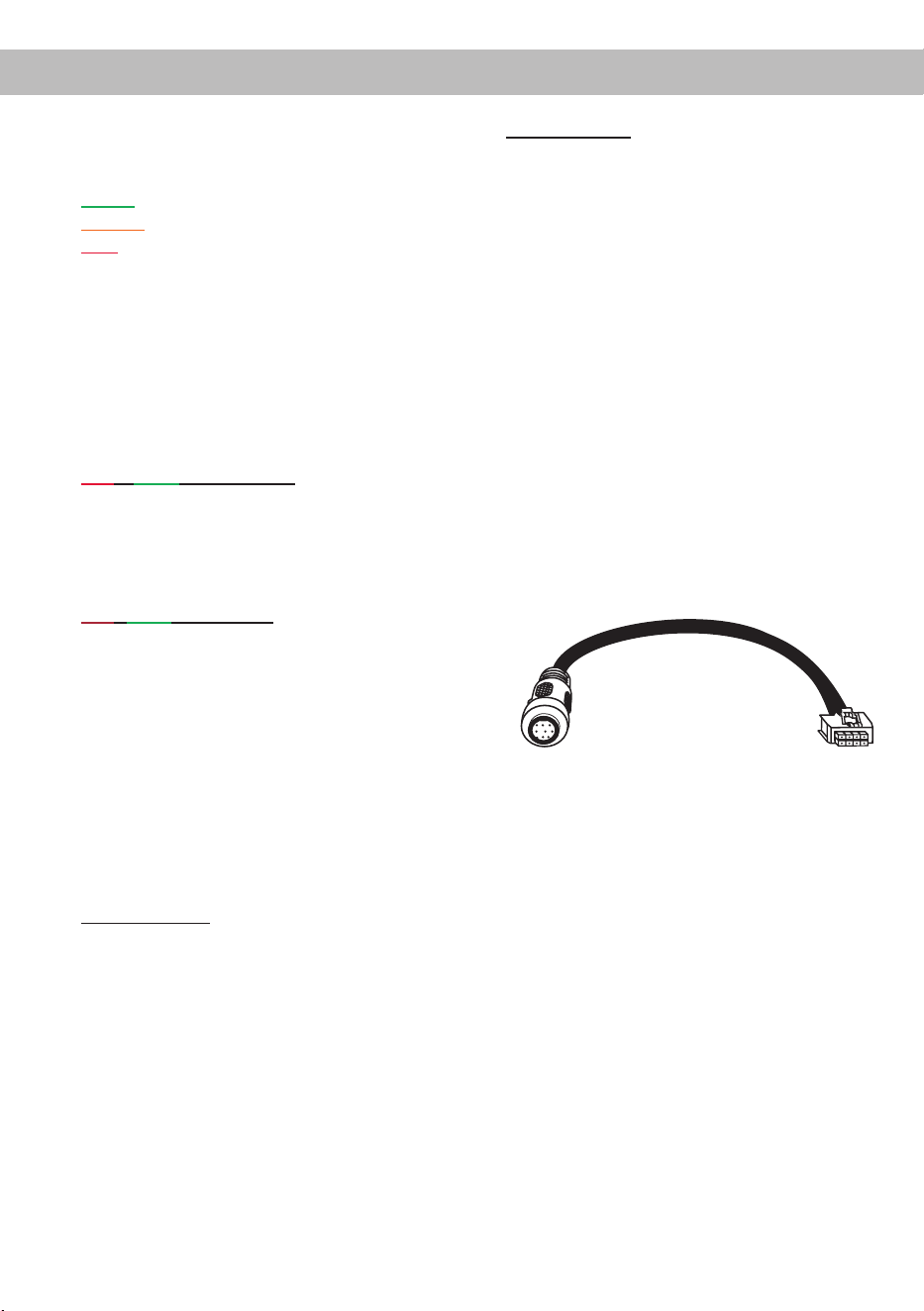
Achtung: Sofern das Zubehörprodukt keinen
NanoFit Stecker besitzt, ist ein SCP-to-Control
Input Adapter (Art-Nr. M141313) optional bei Ih-
rem Fachhändler erhältlich.
SCP-to-Control Input Adapter
Weitere Funktionen
11
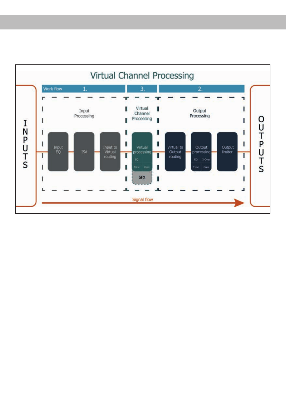
deVirtual Channel Processing (VCP)
Das VCP erweitert den bisherigen Umfang des Gerätes um eine neue Ebene an prozessierten Kanälen, welche
sich zwischen den Ein- und Ausgängen bendet.
Insgesamt stehen acht zusätzliche prozessierte virtuelle Kanäle und neun prozessierte Ausgangskanäle zur
Verfügung.
Diese virtuelle Kanalebene bietet diverse Vorteile, gerade in komplexen Systemkongurationen.
Die Hauptvorteile dieses Konzeptes sind folgende:
- Ausgangskanalübergreifender Gruppen-Equalizer
- Mehrwege-Konguration der DSP-Soundeekte (SFX)
- Zusätzliche Funktionen wie Rear Attenuation
Weiterführende Informationen zum VCP und dessen Konguration nden Sie in unserer Knowledge Base
auf www.audiotec-scher.de/knowledge-base/dsp-pc-tool.
Die MATCH UP 8BMW bietet neben dem Standard Routing das Virtual Channel Processing (VCP), ein
mehrstuges Signalverarbeitungs-Konzept, welches die perfekte Konguration komplexer Soundsysteme
ermöglicht und somit ganz neue Möglichkeiten des Klangtunings erönet.

12
ACO Plattform-Features
Neben den einzigartigen DSP-Sound eekten bietet
die ACO-Plattform der UP 8BMW zusätzlich eine
Vielzahl an System-Features.
Im DCM Menü der DSP PC-Tool Software können
für einige dieser System-Features individuelle Ein-
stellungen vorgenommen werden.
Turn On & O Delay
Hier kann die Verzögerungzeit, mit welcher der
Verstärker ein- und ausgeschaltet werden soll, fest-
gelegt werden. Werkseitig sind 0,2 Sekunden ein-
gestellt. Eine Änderung der Verzögerungszeit sollte
nur vorgenommen werden, wenn es beispielsweise
zu Störgeräuschen beim Ein- und Ausschalten des
Verstärkers kommt.
URC Setup Switch Conguration
Der ACO bietet Speicherplatz für zehn anstelle der
üblichen zwei Sound Setups.
Mit Hilfe einer optional erhältlichen URC Fernbedie
-
nung, oder des Control Tasters (siehe Seite 3) lässt
sich zwischen zwei der zehn Sound-Setup Spei
-
cherplätze umschalten. Diese zwei Speicherplätze
können in der „URC Setup Switch Conguration“
festgelegt werden. Werkseitig sind die Speicherbe
-
reiche eins und zwei ausgewählt.
Um zwischen allen
internen Speicherplätzen umschalten zu können,
werden die optional erhältlichen Fernbedienungen
DIRECTOR und CONDUCTOR empfohlen.
ADEP.3 Conguration
Bei Ansteuerung des Verstärkers über die High-
level-Eingänge kann es in Verbindung mit manchen
Werksradios notwendig sein, den ADEP.3-Schalt-
kreis an den Diagnosemodus des Steuergeräts
anzupassen. Im Bereich „ADEP.3 SB compatibility
mode & Advanced Noise Suppression“ sollte eine
Anpassung vorgenommen werden, wenn es bspw.
zu Fehlfunktionen kommt (Stummschalten des Ra-
dios). Standardmäßig ist der Kompatibilitätsmodus
eingeschaltet (Enabled).

13
deTechnische Daten
Leistung RMS
- Kanal A - F ...................................................................... 6 x 65 @ 4 Ohm
- Sub Out G - H................................................................. 2 x 90 Watt @ 4 Ohm
2 x 160 Watt @ 2 Ohm
Verstärkertechnologie ....................................................... Class GD
Eingänge .......................................................................... 6 x Hochpegel-Lautsprechereingang
1 x Optisch SPDIF (12 - 96 kHz)
1 x Remote In
Eingangsempndlichkeit ................................................... 2,8 - 11 Volt
Eingangsimpedanz ........................................................... 9 - 33 Ohm mit ADEP.3
Ausgänge ......................................................................... 8 x Lautsprecherausgang
1 x Cinch
1 x Remote Out
Ausgangsspannung Cinch................................................3 Volt RMS
Frequenzbereich...............................................................10 Hz - 22.000 Hz
DSP Auösung .................................................................64 Bit
DSP Rechenleistung ........................................................295 MHz (1,2 Mrd. MAC Operationen/Sek.)
Abtastrate .........................................................................48 kHz
DSP Typ ...........................................................................Audio Signalprozessor
Signalwandler ................................................................... A/D: BurrBrown
D/A: BurrBrown
Signal- / Rauschabstand (A-bewertet) ............................. Digitaleingang: 106 dB
Analogeingang: 104 dB
Klirrfaktor (THD) ...............................................................< 0,03 %
Dämpfungsfaktor ..............................................................> 100
Betriebsspannung.............................................................10,5 - 17 Volt (max. 5 Sek. bis hinab zu 6 Volt)
Leistungsaufnahme ..........................................................DC 12 V 40 A max.
Leerlaufstromaufnahme....................................................380 mA
Max. Remote-Ausgangsstrom .......................................... 500 mA
Sicherung .........................................................................1 x 25 A LP-Mini-Stecksicherung
Zusätzliche Features ........................................................ Class GD-Technologie mit dynamisch gere-
geltem Netzteil, 32 Bit CoProcessor, ADEP.3-
Schaltkreis, Start-Stop-Fähigkeit, Smart Control
Port, USB, MEC Slot, Auto Remote-Schalter,
galvanisch getrennter Line Out
Abmessungen (H x B x T) ................................................46 x 130 x 153 mm
Kompatibilität .................................................................... BMW E- & F Modelle sowie G30 / G31 vor
Facelift Modelle mit BMW HiFi Soundsystem
(Option 676), ausgeschlossen Modelle mit RAM-
Modul (Fahrzeuge ab 09/2019).
Montageblech nich passend für 1er Modelle der
E-Serie.
Bitte überprüfen Sie die exakte Fahrzeugkom-
patibilität mit Hilfe unseres Upgrade-Finders auf
www.audiotec-scher.de

14
Garantiehinweis
Die Garantieleistung entspricht der gesetzlichen
Regelung. Von der Garantieleistung ausgeschlos-
sen sind Defekte und Schäden, die durch Überla-
stung oder unsachgemäße Behandlung entstanden
sind. Eine Rücksendung kann nur nach vorheriger
Absprache in der Originalverpackung, einer de-
taillierten Fehlerbeschreibung und einem gültigen
Kaufbeleg erfolgen.
Technische Änderungen, Druckfehler und Irrtümer
vorbehalten!
Für Schäden am Fahrzeug oder Gerätedefekte, her-
vorgerufen durch Bedienungsfehler des Gerätes,
können wir keine Haftung übernehmen. Dieses
Produkt ist mit einer CE-Kennzeichnung versehen.
Damit ist das Gerät für den Betrieb in Fahrzeugen
innerhalb der Europäischen Union (EU) zertiziert.
Hinweis:
„Die Bluetooth
®
Wortmarke und die Logos sind eingetragene Warenzeichen der Bluetooth SIG, Inc. und jegliche Nutzung dieser Marken durch
die Audiotec Fischer GmbH geschieht unter Lizenz. Andere Handelsmarken und Handelsnamen gehören den jeweiligen Inhabern.“
Rechtlicher Hinweis
• MATCH by Audiotec Fischer bzw. die Audiotec Fischer GmbH sind in keiner Weise mit der Baye-
rische Motoren Werke (BMW) AG oder einer ihrer Tochtergesellschaften oder Partnerunternehmen
verbunden, oder handeln in deren Auftrag oder mit deren Autorisierung.
• Alle geschützten Produktnamen und Markennamen sind das Eigentum ihrer jeweiligen Inhaber.
• Die Bluetooth
®
Wortmarke und die Logos sind eingetragene Warenzeichen der Bluetooth SIG, Inc.
und jegliche Nutzung dieser Marken durch die Audiotec Fischer GmbH geschieht unter Lizenz.
Andere Handelsmarken und Handelsnamen gehören den jeweiligen Inhabern.
• Die Kompatibilität entspricht dem Informationsstand von Oktober 2023.
• Technische Änderungen und Irrtum vorbehalten.

15
Dear Customer,
Congratulations on your purchase of this innovative
and high-qual ity MATCH product.
Thanks to more than 30 years of experience in
research and development of audio products this
amplier sets new standards in the range of digital
ampliers.
We wish you many hours of enjoyment with your
new MATCH UP 8BMW.
Yours,
AUDIOTEC FISCHER
General installation instructions for MATCH
components
To prevent damage to the unit and possible injury,
read this manual carefully and follow all installation
instructions. This product has been checked for
proper function prior to shipping and is guaranteed
against manufacturing defects.
Before starting your installation, disconnect the
battery’s negative terminal to prevent damage
to the unit, re and / or risk of injury. For a proper
performance and to ensure full warranty coverage,
we strongly recommend to get this product installed
by an authorized MATCH dealer.
Install your UP 8BMW in a dry location with su-
cient air circulation for proper cooling of the equip-
ment.
For safety reasons, the UP 8BMW must be profes-
sionally installed. Therefore, use the two mounting
plates which are included in delivery. These are at-
tached to the bottom of the amplier with two short
screws which are included in delivery, too.
When screwing the amplier to the vehicle chassis,
carefully examine the area around and behind the
proposed installation location to ensure that there
are no electrical cables or components, hydraulic
brake lines or any part of the fuel tank located be-
hind the mounting surface. Failure to do so may re-
sult in unpredictable damage to these components
and possible costly repairs to the vehicle.
General instruction for connecting the UP 8BMW
amplier
The UP 8BMW amplier may only be installed in
motor vehicles which have a 12 Volts negative ter-
minal connected to the chassis ground. Any other
system could cause damage to the amplier and
the electrical system of the vehicle. Only neces-
sary if the UP 8BMW is directly powered via the
cars battery (Page 20, point 4): The positive cable
from the battery for the entire sound system should
be provided with a main fuse at a distance of max.
30 cm from the battery. The value of the fuse is cal-
culated from the maximum total current draw of the
car audio system.
Use only the included MATCH cable for con-
nection of the UP 8BMW. The use of other
cables can result in damage of the ampli-
er, the head unit / car radio or the connected
loudspeakers! The fuse of the amplier may
only be replaced by an identically rated fuse
(25 A) to avoid damage of the amplier.
Prior to installation, plan the wire routing to avoid
any possible damage to the wire harness. All
cabling should be protected against possible
crushing or pinching hazards. Also avoid routing
cables close to potential noise sources such as
electric motors, high power accessories and other
vehicle harnesses.
Congratulations!
General instructions
en
16
Connectors and control units
1
Speaker Output E - H
Page 19, point 2
2
Highlevel Input E & F
Not used by BMW HiFi sound upgrade
3
System Connector input
Page 19, point 2
4
Remote connectors
Page 19, point 2
5
Optional: Power connector
Page 20, point 4
6
USB input
Page 20, point 5
7
Control pushbutton
Page 23, point 2
8
Auto Remote switch
Page 20, point 3
9
SCP (Smart Control Port)
Page 23, point 3
10
Optical Input
Not uused by BMW HiFi sound upgrade
11
Line Output
Not used by BMW HiFi sound upgrade
12
Status LED
Page 23, point 1
1 2 3 4 5
6
7 8 9 10 11
12
17
enHardware conguration
Fig. 1: Pin conguration UP 8BMW
System Connector
1. Highlevel loudspeaker input rear left (-) / C
2. Highlevel loudspeaker input front left (-) / A
3. Highlevel loudspeaker input front right (-) / B
4. Highlevel loudspeaker input rear right (-) / D
5. Loudspeaker output rear right (-) / D
6. Loudspeaker output rear left (-) / C
7. Loudspeaker output front right (-) / B
8. Loudspeaker output front left (-) / A
9. Ground
10. Ground
11. Highlevel loudspeaker input rear left (+) / C
12. Highlevel loudspeaker input front left (+) / A
13. Highlevel loudspeaker input front right (+) / B
14. Highlevel loudspeaker input rear right (+) / D
15. Loudspeaker output rear right (+) / D
16. Loudspeaker output rear left (+) / C
17. Loudspeaker output front right (+) / B
18. Loudspeaker output front left (+) / A
19. +12 Volts
20. +12 Volts
Highlevel Input E - F
21. Not used by BMW HiFi sound upgrade
22. Not used by BMW HiFi sound upgrade
23. Not used by BMW HiFi sound upgrade
24. Not used by BMW HiFi sound upgrade
Speaker Output E - H
25. Subwoofer output right (-) / H
26. Subwoofer output left (-) / G
27. Not used by BMW HiFi sound upgrade
28. Center speaker output (-) / E
29. Subwoofer output right (+) / H
30. Subwoofer output left (+) / G
31. Not used by BMW HiFi sound upgrade
32. Center speaker output (+) / E
28272625
2019181716151413121132313029 2423
2221 10987654321
18
Hardware conguration
Fig. 2: Pin assignment Power Input plug
Plug top side
A
+12 V – for connecting the UP 8MBW to the positive
terminal of the car´s battery.
B
GND – for connecting the gorund cable.
A
B
ATTENTION: The Power Input must not be used in parallel with the power input of the System Con-
nector / plug & play cable harness. In case the Power Input is used it is absolutely necessary to make
hardware congurations on the amplier (see page 20, point 4).
19
en
Mount and congure the MATCH UP 8BMW as
follows
Caution: Carrying out the following steps will re-
quire special tools and technical knowledge. In
order to avoid connection mistakes and / or dam-
age, ask your dealer for assistance if you have any
questions and follow all instructions in this manual
(see page 15).
1. Removal of the original amplier
a. Carefully remove the car interior lining that
covers the original amplier. In most cases it
is the left side panel in the trunk.
Note: The car interior lining is fastened with
several hidden screws to the metal sheet of
the car. Make sure that you have loosened
all screws before you try to remove it.
Additionally it is often xed by numerous
plastic clips. When removing the car interior
lining the ambient temperature should not be
below 10°C.
b. First disconnect all cables from the device.
c. Loosen the bolting between the mounting
plate of the amplier and the original mount-
ing xture of the vehicle body (Depending on
the model, it may be necessary to dismatle
the original mounting xture beforehand).
Then, pull out the original amplier sideways
or upwards, depending on the type of instal-
lation.
2. Installation of the UP 8BMW amplier
a. Fix the mounting panel with the counter-sunk
screws (both included in delivery) to the bot-
tom plate of the UP 8BMW.
b. Connect the male connectors of the MATCH
connection cable to the amplier (System
Connector, Speaker Output E - H and REM).
c. Push the amplier including the mounting
plate onto the original mounting xture in the
vehicle.
d. Bolt the mounting plate to the original mount-
ing xture in the vehicle again.
e. Finally connect the female connector of the
UP 8BMW connection cable (1) to the male
connector of the vehicle cable harness (2).
1
2
20
3. Conguration of the remote input
If the UP 8BMW replaces the amplier of the
BMW HiFi sound system (676), the amplier is
turned on via the remote cable of the enclosed
cable harness. The Auto Remote switch must
be set to “O.”
On: Activation via highlevel speaker input.
O: Activation via remote signal (by default).
Note: If the automatic turn-on function is deac-
tivated it is mandatory to use the remote input
terminal to power up the amplier!
4. Optional: Connection to power supply
In default application as BMW HiFi sound up-
grade the UP 8BMW will be directly powered
from the original cable harness of the vehicle
via the included plug & play connection cable.
A direct power supply via the vehicles battery
may be necessary if:
- the UP 8BMW is used outside the standard
application as BMW HiFi sound upgrade
- more powerful speakers (e.g. 3 Ω HELIX
COMPOSE speakers) are connected or
- more powerful subwoofers (e.g. 2 Ω MATCH
UPGRADE subwoofers or 2 Ω HELIX COM-
POSE speakers) are connected.
In this case it is mandatory to make the follow-
ing hardware conguration inside the amplier.
a. Remove mounting plate and open the am-
plier
Remove the amplier’s mounting plate by
loosening the four countersunk screws.
Then, remove the side panel with the “Sys-
tem Connector” input by loosening the two
Phillips screws and pull out the bottom plate
to the side.
b. Remove fuse
Remove the marked 25 A fuse by simply pull-
ing it upwards.
c. Insert two fuses
Insert the previously removed 25 A fuse and
the included 25A fuse into the slots marked in
the image below.
d. Assemble the amplier and attach the
mounting plate
Reassemble the amplier as previously de-
scribed in reverse order
e. Connect power supply to the Power Input
IMPORTANT: Before connecting the +12 V
power supply cable to the vehicle’s electrical
system, disconnect the car battery.
Make sure to disconnect the battery before
installing the MATCH UP 8BMW!
Solely use the Power Input plug which is in-
cluded in delivery for connection (see page 18,
g. 2). Make sure of correct polarity.
+12 V: Connect the +12 V power cable to the
positive terminal of the battery. The positive
wire from the battery to the amplier power ter-
minals needs to have an inline fuse (50 A) at a
distance of less than 12 inches (30 cm) from
the battery. If your power wires are short (less
than 1 m / 40”) then a wire gauge of 6 mm² /
AWG 10 will be sucient. In all other cases we
strongly recommend gauges of 10 - 16 mm² /
AWG 8 – 6!
GND: Connector for the ground cable. The
ground wire must be connected to the vehicle
chassis at a non-insulated point. The cable
should have the same gauge as the +12 V wire.
Inadequate grounding causes audible interfer-
ence and malfunctions.
5. Connecting the PC & rst start-up
The USB input enables the connection of the
UP 8BMW to a personal computer and its free
conguration with our DSP PC-Tool software
using the provided USB cable.
Please note: It is not possible to connect any
USB storage devices.
Prior to connecting the amplier to your PC visit
our website and download the latest version of
Hardware conguration

21
en
the DSP PC-Tool software.
We strongly recommend to carefully read the
DSP PC-Tool knowledge base before using the
software for the rst time in order to avoid any
complications and failures.
Important: Make sure that the amplier is not
connected to your computer before the soft-
ware and USB driver are installed!
In the following the most important steps how
to connect and the rst start-up are described:
a. Download the latest version of the DSP
PC-Tool software (available on our website
www.audiotec-scher.com) and install it
on your computer.
b. Connect the amplier to your computer us-
ing the USB cable that is included in deliv-
ery. If you have to bridge longer distances
please use an active USB extension cable
with integrated repeater.
c. First turn on the amplier and then start the
software. The operating software will be up-
dated automatically to the latest version if it
is not up-to-date.
6. Conguration of the internal DSP
The general amplier settings should be
conducted with the DSP PC-Tool software
before using the amplier for the rst time.
Now you are able to install a car-specic sound
setup to the amplier and adapt it to your indi-
vidual requirements or congure it individually.
Read in the following the steps how to install
a car-specic sound setup to the DSP of the
UP 8BMW:
a.
Download a car-specic sound set-
up from the Audiotec Fischer website
( www . audiotec - scher . com). The database
can be found under the menu item Tools →
Sound Setups
.
b. Then select your device, vehicle make and
model. Next you can choose an appropriate
sound setup le from the list and download it.
c. Now connect the UP 8BMW to your comput-
er, as described before, and start the DSP
PC-Tool software.
d. Load the previously downloaded sound setup
le into the DSP PC-Tool software.
e. Optionally you can now customize the sound
setup with the DSP PC-Tool to your needs.
f. Once you have made all the settings, save
the sound setup on the DSP of the UP 8BMW.
Useful hints for the correct setting can
be found in our knowledge base at
www.audiotec-scher.com.
Caution: We highly recommended to set the
volume of your car radio to minimum position
and to mute all signal outputs. Especially if the
UP 8BMW will be used in fully active applica-
tions, a wrong setup can destroy your speakers
right away.
7. Adjustment of the input sensitivity of the an-
alog inputs
ATTENTION: It is mandatory to properly
adapt the input sensitivity of the UP 8BMW
to the signal source in order to avoid dam-
age to the amplier.
The input sensitivity can be optimally adapted to
the signal source using the DSP PC-Tool soft-
ware. Input sensitivity is factory set to 11 Volts.
This is denitely the best setting in most appli-
cations. Only if the head unit / car radio doesn t
deliver enough output level, the input sensitivity
should be increased.
Note: Mute all signal outputs of the UP 8BMW
during this setup.
For adjustment of the input sensitivity please
proceed as follows:
a. Turn on the amplier.
b. Start the DSP PC-Tool software.
c. The adjustment of the input sensitivity can
be found in the “Signal Management” tab of
the DCM menu under the item “Main Input →
Input Gain”.
d. Select the setup method to adjust the input
sensitivity.
Standard Gain Setup: This method allows go
globally set the input sensitivity for all input
22
channels (only with “Low Voltage Range”
jumper plug-in position – see left).
Advanced Gain Setup: This method allows
an individual setting for each channel pair.
e. Adjust the volume of your radio to approx.
90 % of the max. volume and playback an
appropriate test tone, e.g. pink noise (0 dB).
f. If the clipping indicator in the DSP PC-Tool
already lights up (see following picture), you
have to reduce the input sensitivity using the
scroll bar until the indicator turns o.
g. Increase the input sensitivity until the clip-
ping indicator lights up. Now turn the control
back until the indicator turns o again.
8. Mounting the car interior lining
After the UP 8BMW has been properly installed
and all adjustments have been made to the am-
plier, the car interior lining can be reattached.
Caution:
The UP 8BMW amplier has a higher power
output than the original head unit / original am-
plier. In most cases the original loudspeakers
will be able to handle the extra power in com-
bination with the correct DSP adjustments. In
the case you make your own adjustments to the
DSP it might be possible that the original speak-
ers get overloaded and / or damaged. Therefore
we always recommend to ensure that there are
no sound distortions especially at high volumes
to avoid any damage to the speakers.
Note: Audiotec Fischer is not responsible for
any damages to OE speakers that are used in
combination with the UP 8BMW! In order to avoid
damages, ask your MATCH specialized dealer for
assistance.
Hardware conguration
23
enAdditional functions
1. Status LED
The Status LED indicates the operating mode
of the amplier and of the DSP memory.
Green: Amplier is ready for operation.
Orange: Power Save Mode is activated.
Red: Protection Mode is active. This may have
dierent root causes. The amplier is equipped
with protection circuits against over- and under-
voltage as well as overheating. Please check
for connecting failures such as short-circuits or
other wrong connections.
If the amplier is overheated the internal tem-
perature protection switches o the remote and
signal output until it reaches a safe temperature
level again.
Red / green slow ashing: No operating soft-
ware installed. Connect the amplier to the DSP
PC-Tool software and conrm the automatic up-
date of the operating system. You will nd the
latest version of the DSP PC-Tool software at
www.audiotec-scher.com.
Red / green fast ashing: The currently selected
sound setup memory is empty. A new setup has
to be loaded via the DSP PC-Tool software or
switch to a memory position with existing sound
setup.
2. Control pushbutton
The UP 8BMW provides 10 internal memory
locations for sound setups. The Control push-
button allows the user to switch between two
memory positions. These can be dened in the
DSP PC-Tool. In addition a device reset can be
made by pressing the button for a longer period.
1. Setup switch: Press Control pushbutton for
1 second. The memory locations one and two
are dened by default. Switching is indicated
by a single red ash of the Status LED. Alter-
natively, the optional URC.3 remote control can
be used for switching. To switch between all in-
ternal memory locations, optional accessories
like the DIRECTOR display remote control or
CONDUCTOR are required.
2. Device reset: Press pushbutton for ve sec-
onds. This completely erases the internal mem-
ory and is indicated by a continuous red glowing
and constant green ashing of the Status LED.
Attention: After erasing the setups from mem-
ory the UP 8BMW will not reproduce any audio
output until the device is updated via the DSP
PC-Tool software.
3. SCP (Smart Control Port)
This multi-functional input is designed for
MATCH UP 8BMW accessory products like a
remote control which allows to adjust several
features of the amplier. Depending on the type
of remote control, at rst its functionality has to
be dened in the “ Device Conguration Menu”
of the DSP PC-Tool software.
Attention: If the accessory product does not
have a NanoFit connector, a SCP-to-Control
Input adaptor (Art-Nr. M141313) is optionally
available from your specialist dealer.
SCP-to-Control Input adaptor

24
Virtual Channel Processing (VCP)
The VCP extends the previous scope of the device by an additional layer of processed channels, which
is located between the inputs and outputs. A total of eight additional processed virtual channels and nine
processed output channels are available.
This virtual channel layer oers several advantages, especially in complex system congurations.
The main advantages of this concept are:
- Cross-channel group equalizers that aect several output channels simultaneously
- Multi-way speaker conguration of DSP sound eects (SFX)
- Additional features such as Rear Attenuation
For further information about the VCP and its conguration, please refer to our Knowledge Base at
www.audiotec-scher.com/knowledge-base/dsp-pc-tool.
In addition to standard routing, the MATCH UP 8BMW oers Virtual Channel Processing (VCP), a multi-
stage signal processing concept that enables the perfect conguration of complex sound systems,
opening up completely new possibilities for sound tuning.

25
enACO platform features
Beside the unique DSP sound eects the UP 8BMW
provides a bunch of new system features.
In the DCM menu of the DSP PC-Tool software in-
dividual settings can be made for several of these
system features.
Turn On & O Delay
This function allows to determine the delay time
with which the integrated DSP is switched on and
o. The factory setting is 0.2 seconds. The delay
time should only be modied if there are e.g. noises
while switching on / o the amplier.
URC Setup Switch Conguration
The ACO provides ten internal memory locations for
sound setups instead of the common two.
By using an optional URC remote control or the
Control pushbutton (see page 20) it is possible to
toggle between two of the ten memory locations.
These two memory locations can be determined in
the “URC Setup Switch Conguration”. The memory
locations one and two are preassigned by default.
To switch between all internal memory locations, the
optionally available remote controls DIRECTOR and
CONDUCTOR are recommended.
ADEP.3 Conguration
If the UP 8BMW is connected to an OEM radio via
the highlevel inputs it may happen that the ADEP.3
circuit has to be adapted to the diagnostic mode of
the radio if the latter is equipped with a so-called
“class SB” output stage.
In the “ADEP.3 SB compatibility mode & Advanced
Noise Suppression” section, an adjustment should
be made if there are e.g. distortions occur in the
upper volume range.
The compatibility mode is enabled by default.
26
Installation of a MATCH Extension Card
It is possible to extend the functionality of the
MATCH UP 8BMW by inserting an optional MATCH
Extension Card (MEC) – for example a High De-
nition Bluetooth
®
Audio Streaming module, a High
Resolution Audio USB soundcard etc.
To install a MATCH Extension Card it is necessary
to remove the side panel of the UP 8BMW and re-
place it by the new side panel that comes with the
MEC module.
Attention: Install the MEC module only in the
designated device and its specic slot. Using
the MEC module in other devices or slots can
result in damage of the MEC module, the ampli-
er, the head unit / car radio or other connected
devices!
Read in the following the steps how to install a MEC
module:
1. First disconnect all cables from the device.
2. Dismantle the side panel where the USB input
is located by removing the Phillips screws.
3. Pull out the bottom plate.
4. Prepare the module for installing it into the de-
vice. Any further mounting information will be
found in the instruction manual of the respective
MEC module.
5. Insert the MEC module into the specic slot of
the device which is marked in the following pic-
ture.
6. Make sure that the MEC module is installed
properly and all pins are fully inserted into the
socket.
7. Reinsert the bottom plate and x the new side
panel which is delivered with the MEC module
with the Phillips screws.
8. Bolt the MEC module to the side panel. Pre-
cise mounting information will be found in
the instruction manual of the respective MEC
module.
9. Reconnect all cables to the device.
10. Turn on the amplier. The MEC module is auto-
matically detected by the device and the Status
LED of the MEC module lights up green.
11. Now you are able to congure the MEC module
in the DSP PC-Tool software.

27
enTechnical Data
Output power RMS
- Channel A - F................................................................ 6 x 65 Watts @ 4 Ohms
- Sub Out G - H............................................................... 2 x 90 Watts @ 4 Ohms
2 x 160 Watts @ 2 Ohms
Amplier technology ....................................................... Class GD
Inputs .............................................................................. 6 x Highlevel speaker input
1 x Optical SPDIF (12 - 96 kHz)
1 x Remote In
Input sensitivity ............................................................... 2.8 - 11 Volts
Input impedance ............................................................. 9 - 33 Ohms with ADEP.3
Outputs ........................................................................... 8 x Speaker output
1 x RCA / Cinch
1 x Remote Out
Output voltage RCA / Cinch............................................ 3 Volts RMS
Frequency response ....................................................... 10 Hz - 22,000 Hz
DSP resolution ................................................................ 64 Bit
DSP power ..................................................................... 295 MHz (1.2 billion MAC operations/sec.)
Sampling rate ................................................................. 48 kHz
DSP type ........................................................................ Audio signal processor
Signal converters ............................................................ A/D: BurrBrown
D/A: BurrBrown
Signal-to-noise ratio (A-weighted) .................................. Digital input: 106 dB
Analog input: 104 dB
Distortion (THD) .............................................................. < 0.03 %
Damping factor ............................................................... > 100
Operating voltage ........................................................... 10.5 - 17 Volts (max. 5 sec. down to 6 Volts)
Power rating ................................................................... DC 12 V
40 A max.
Current draw ................................................................... 380 mA
Max. remote output current ............................................ 500 mA
Fuse................................................................................ 1 x 25 A LP-Mini-fuse (APS)
Additional features .......................................................... Class GD technology with dynamically controlled
power supply, 32 Bit CoProcessor, ADEP.3 circuit,
Start-Stop capability, Smart Control Port, USB,
MEC slot, Auto Remote switch, galvanically isolat-
ed Line Out
Dimensions (H x W x D) ................................................. 46 x 130 x 153 mm / 1.81 x 5.12 x 6.02”
Compatibility ................................................................... BMW E & F and G30 / G31 before facelift
models with BMW HiFi sound system (option
676), all models with RAM module are excluded
(vehicles from 09/2019). Mounting plate is not
suitable for 1-series E models. Please check
vehicle compatibility using our upgrade nder at
www.audiotec-scher.com
The warranty service is based on the statutory reg-
ulations. Defects and damage caused by overload
or improper handling are excluded from the warran-
ty service. Any return can only take place following
prior consultation, in the original packaging together
with a detailed description of the error and a valid
proof of purchase.
Technical modications, misprints and errors ex-
cepted! We accept no liability for damage to the
vehicle or device defects caused by the incorrect
operation of the device. This product has been is-
sued a CE marking. This means that the device
is certied for use in vehicles within the European
Union (EU).
Warranty Disclaimer
Note:
“The Bluetooth
®
word mark and logos are registered trademarks owned by Bluetooth SIG, Inc. and any use of such marks by
Audiotec Fischer GmbH is under license. Other trademarks and trade names are those of their respective owners.”

Audiotec Fischer GmbH
Hünegräben 26 · 57392 Schmallenberg · Germany
Tel.: +49 2972 9788 0 · Fax: +49 2972 9788 88
E-mail: match@audiotec-scher.com · Internet: www.audiotec-scher.com
Made in Germany