
PS254DB
Original instructions

2
2
Important!
It is essential that you read the instructions in this manual before
assembling, operating and maintaining the product.
Subject to technical modifications.
3
3
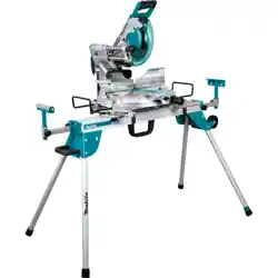
The following tools (not included) are needed for making adjustments:
COMBINATION SQUARECOMBINATION WRENCHFRAMING SQUARE
Ø 254 mm
n
max.
7000
Ø 30 mm
48 HW 2.2 mm
25
26
4
5
13
10
11
14
16
6
18
21
12
1
8
7
8
9
15
6
22
20
24
23
38
17
19
17
2
3
37
32
34
31
29
30
28
2
33
35
36
27
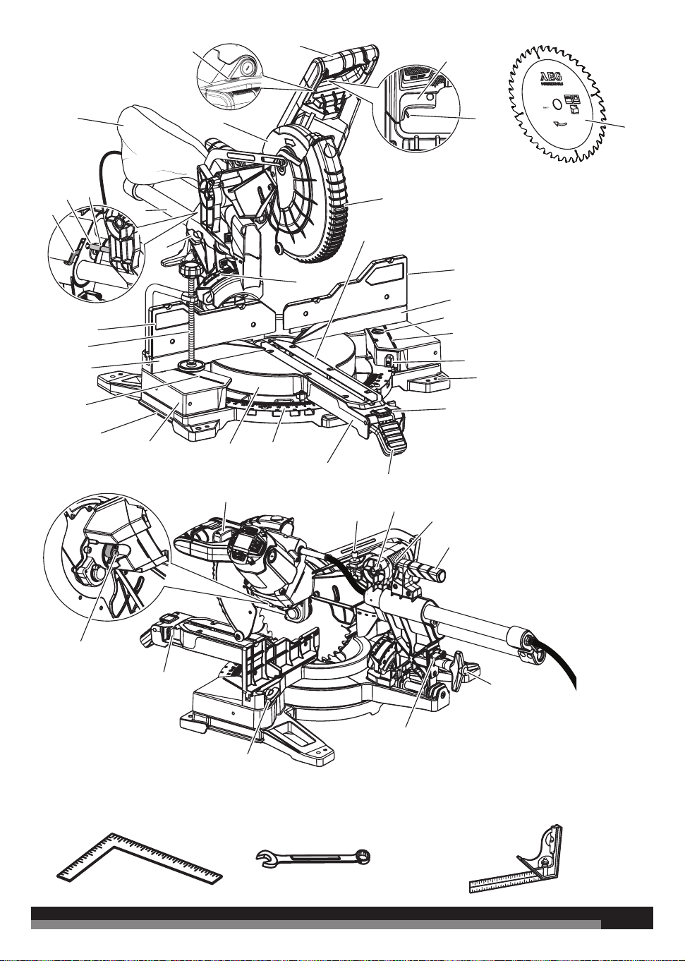
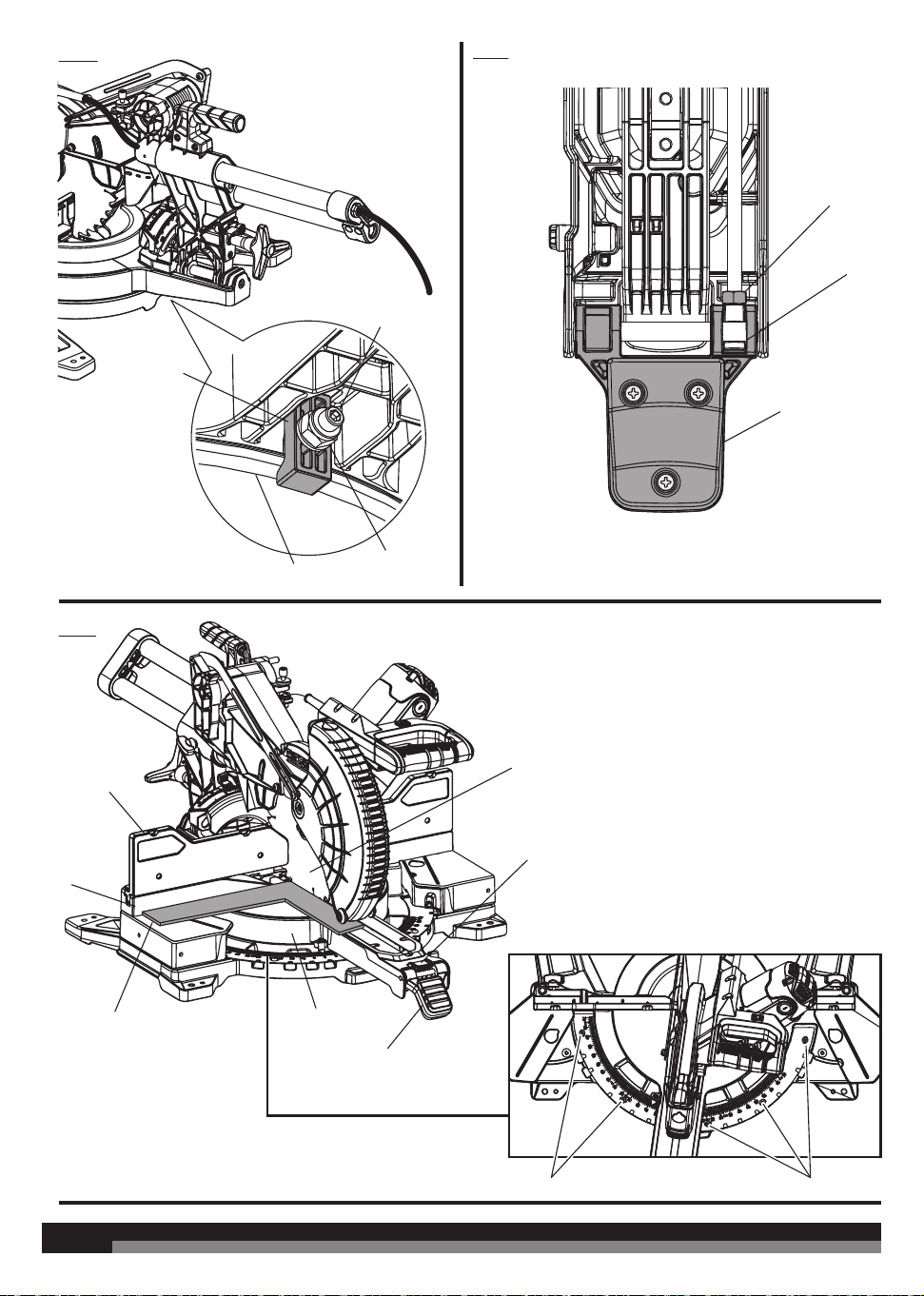
1. “D” Handle
2. Switch trigger
3. Switch lock off
4. Lower blade guard
5. Throat plates
6. Sliding fence
7. “No hands zone” label
8. “No hands zone” boundary line
9. Table lock button
10. Mitre detent bypass button
11. Mitre lock lever
12. Control arm
13. Mitre scale
14. Turning table
15. Rotating extension table
16. Saw base
17. Fixed fence
18. Work clamp
19. Mounting holes x 4
20. Slide lock knob
21. Slide bar
22. Crown and baseboard setting
lever
23. Crown stop
24. Baseboard lock groove
25. Dust bag
26. Upper blade guard
27. LED switch
28. Depth control knob
29. Head lock pin
30. Blade wrench storage
31. Carrying handle
32. Bevel lock knob
33. Bevel detent lever
34. Fence lock knob
35. Mitre detent override lever
36. Spindle lock button
37. Saw blade
38. Bevel scale
4
4
M8
M8
M8
M8
1
1
1
2
3
2
2
1
2
3
4
3
1
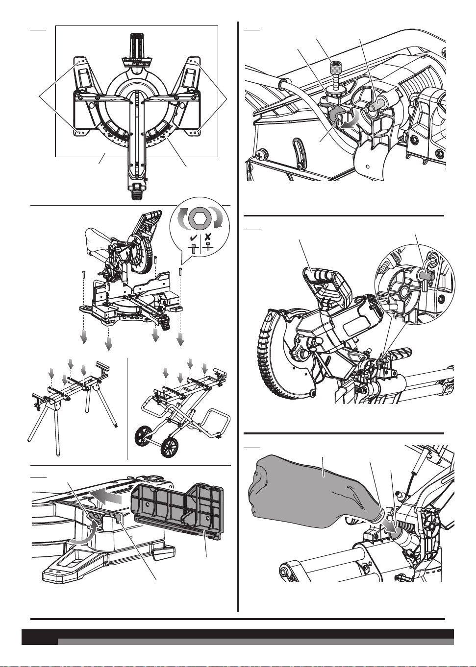
Fig. 3
Fig. 4
1 - “D” handle
2 - Head lock pin
1 - Dust bag
2 - End of frame assembly
3 - Exhaust port
Fig. 5
1 - Mounting holes
2 - Mounting surface
3 - Base
PSU1000 PSUM1000
2
3
Fig. 2
1
1 - Depth control knob
2 - Lock nut
3 - Depth stop
4 - Head lock pin
1 - Sliding fence
2 - Fence lock knob
3 - Slot
Fig. 1
5
5
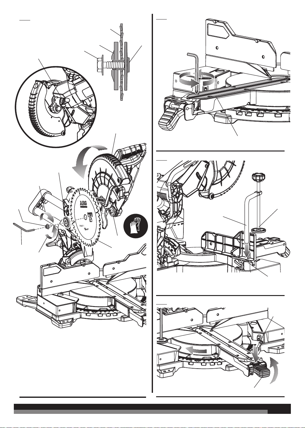
Fig. 6
Ø 254 mm
n
max.
7000
Ø 30 mm
48 HW 2.2 mm
Fig. 7
1 - Work clamp shaft
2 - Work clamp
3 - Work clamp hole
Fig. 8
Fig. 9
1 - Spindle lock button
2 - Saw blade
3 - Outer flange
4 - Blade bolt
5 - Arbor
6 - Lower blade guard
7 - Blade wrench
1 - Adjustable throat plate
1
1
1
2
3
2
3
4
5
6
3
4
7
To tighten
2
5
1 - Mitre detent bypass button
2 - Mitre lock lever
1
2
To loosen
6
6
Fig. 10
Fig. 12
Fig. 11
1 - Mitre lock shoe
2 - Mitre lock screw
3 - Saw base
4 - Mitre lock nut
1 - Sliding fence
2 - Fixed fence
3 - Framing square
4 - Turning table
5 - Mitre lock lever
6 - Mitre detent bypass button
7 - Saw blade
8 - Screws
1 - Mitre lock nut
2 - Mitre lock screw
3 - Mitre lock lever
Underside of mitre lock lever
1
1
2
3
2
3
1
2
3
4
7
6
5
88
4
7
7
Fig. 13
Fig. 14
Fig. 15
Fig. 16
1 - Handle
2 - Detent disengaged
3 - Detent engaged
4 - Bevel detent lever
5 - Bevel lock knob
6 - To tighten
7 - To loosen
1 - Mitre scale
2 - Scale indicator
1 - Saw blade
2 - Framing square
3 - Turning table
4 - Fixed frence
1 - Saw blade
2 - Framing square
3 - Turning table
4
3
1
1
1
2
2
3
4
5
6
7
1
1
3
2
View of blade not square with
fence, adjustments are required.
View of blade not square with
turning table, adjustments are required.
2
1
4
2
2
8
8
Fig. 17
Fig. 18
Fig. 19
Fig. 20
1 - Screws
2 - Bevel lock dust cover
3 - Bevel lock knob
4 - Bevel detent lever
1 - Screws
2 - Bevel detent plate
3 - Micro adjust screw
1
1
1
11
2
3
2
2
2
3
4
1 - LED switch
2 - Shadow of blade teeth projected onto workpiece
1 - Slide lock knob
2 - Work clamp
Back of bevel lock bracket
CROSS CUT
Front of bevel lock bracket
9
9
Fig. 21
Fig. 22
Fig. 23
1 - Handle
2 - Detent disengaged
3 - Detent engaged
4 - Bevel detent lever
5 - Bevel lock knob
6 - To tighten
7 - To loosen
Fig. 24
Fig. 25
Fig. 26
1 - Work clamp
1 - Sliding fence
2 - Rotating extension table
2
1 - Table lock button
1 - Work clamp
1
1
1
1
MITRE CUT
EXTENDED MITRE CUT
BEVEL DETENT LEVER
BEVEL CUT
1
2
5
7
3
4
6
10
10
Fig. 27
Fig. 28
Fig. 29
1 - Long workpiece
2 - Workpiece supports
Fig. 30
Fig. 31
Fig. 32
1 - Compound mitre cut
1 - Slide saw arm forward
2 - Push down
3 - Push back
1 - Auxiliary fence
2 - Align board with edge of mitre table
1 - Wide board
SLIDE CUT
45º x 45º COMPOUND MITRE CUT
1
1
2
1
1
2
1
2
3
11
11
Ceiling
Wall
Ceiling
Wall
1 - Depth control knob
2 - Lock nut
3 - Depth stop
2
3
4
1
1
2
3
Fig. 33
Fig. 36
Fig. 37
38°
52°
45°
45°
2
Top edge against fence:
s-FGUTJEFJOTJEFDPSOFS
s3JHIUTJEFPVUTJEFDPSOFS
1
Fig. 34
1 - Sliding fence
2 - Mitre table
1
3
4
Top edge against fence:
s-FGUTJEFJOTJEFDPSOFS
s3JHIUTJEFPVUTJEFDPSOFS
2
1 - Inside corner
2 - Sliding fence
3 - Outside corner
4 - Mitre table
Fig. 35
1 - Work clamp
2 - C clamp
3 - Workpiece
4 - Spacer
1
2
3
1 - Cut these grooves with saw
2 - Use a chisel to cut out the middle
3 - Workpiece
12
12
Fig. 38
Fig. 39
Fig. 40
Fig. 41
Fig. 42
1 - Hole “A”
2 - Crown stop
3 - Hole “B”
4 - Crown stop lock knob
1 - Slide lock knob
2 - Crown and baseboard setting lever
3 - Crown stop
4 - Baseboard lock groove
RIGHT
WRONG
3
3
2
2
1
1
1
4
4

13
13
TECHNICAL DATA SLIDING COMPOUND MITRE SAW
PS254DB
Rated input 220V - 240V ~ 50 Hz
Rated current 7.5 A
Rated power 1800 W
Weight 24.6 kg
Maximum cutting depth 89 mm
No-load speed 4800 min
-1
Saw blade diameter x hole diameter 254 x 30 mm
Saw blade thickness / kerf 1.8 mm / 2.5 mm
Maximum cutting capacity
Mitre 0°/ Bevel 0° Hi-capacity 89 mm x 305 mm
Mitre 45°/ Bevel 0° 89 mm × 203 mm
Mitre 0°/ Bevel 45° (left) 51 mm × 305 mm
Mitre 0°/ Bevel 45° (right) 38 mm × 305 mm
Mitre 0°/ Bevel 48° (left) 38 mm × 305 mm
Mitre 0°/ Bevel 48° (right) 19 mm × 305 mm
Mitre 45°/ Bevel 45° (left) 51 mm × 203 mm
Mitre 45°/ Bevel 45° (right) 38 mm × 203 mm
Mitre 45°/ Bevel 48° (left) 38 mm × 203 mm
Mitre 45° (left) / Bevel 48° (right) 19 mm × 203 mm
Mitre 70°/ Bevel 0° 38 mm × 102 mm
Vertical Base (laid flat on turning table)
Mitre 45°/ Bevel 0° 153 mm × 19 mm
Nested Crown (laid flat on turning table)
Mitre 45°/ Bevel 0° 168 mm
Maximum mitre angle 70°
Maximum bevel angle 48°
Minimum workpiece dimensions 215 mm × 35 mm × 2.5 mm
Measured values determined according to EN 62841
A-weighted sound pressure level
L
pA
= 95.2 dB(A)
Uncertainty K K = 3 dB(A)
Measured values determined according to EN 62841
A-weighted sound power level
L
wA
= 108.1 dB(A)
Uncertainty K K = 3 dB(A)
WARNING!
The declared noise emission value(s) have been measured in accordance with a standard test method of EN 62841-1 and EN 62841-3-9, and
may be used for comparing one tool with another.
The declared noise value(s) may also be used in a preliminary assessment of exposure.
The noise emissions during actual use of the power tool can dier from the declared values depending on the ways in which the tool is used
especially what kind of workpiece is processed.
Identify safety measures to protect the operator based on an estimation of exposure in the actual conditions of use (taking account of all parts
of the operating cycle such as the times when the tool is switched o and when it is running idle in addition to the trigger time).
Wear hearing protection. Exposure to noise can cause hearing loss.
REPLACEMENT PARTS
Saw blade 089315001009
Combination wrench 089240013065
Work clamp 089315001301
Dust bag 089315001302
Throat plate 089240013085
Crown stop 089041028721
Brush 089041028055

14
14
GENERAL POWER TOOL SAFETY WARNINGS
WARNING! Read all safety warnings, instructions, illustrations
and specifications provided with this power tool. Failure to follow
all instructions listed below may result in electric shock, fire and/or
serious injury.
Save all warnings and instructions for future reference.
The term “power tool” in the warnings refers to your mains-operated
(corded) power tool or battery-operated (cordless) power tool.
WORK AREA SAFETY
Keep work area clean and well lit. Cluttered or dark areas invite
accidents.
Do not operate power tools in explosive atmospheres, such as
in the presence of flammable liquids, gases or dust. Power tools
create sparks which may ignite the dust or fumes.
Keep children and bystanders away while operating a power tool.
Distractions can cause you to lose control.
ELECTRICAL SAFETY
Power tool plugs must match the outlet. Never modify the plug in
any way. Do not use any adapter plugs with earthed (grounded)
power tools. Unmodified plugs and matching outlets will reduce risk
of electric shock.
Avoid body contact with earthed or grounded surfaces, such as
pipes, radiators, ranges and refrigerators. There is an increased
risk of electric shock if your body is earthed or grounded.
Do not expose power tools to rain or wet conditions. Water
entering a power tool will increase the risk of electric shock.
Do not abuse the cord. Never use the cord for carrying, pulling or
unplugging the power tool. Keep cord away from heat, oil, sharp
edges or moving parts. Damaged or entangled cords increase the
risk of electric shock.
When operating a power tool outdoors, use an extension cord
suitable for outdoor use. Use of a cord suitable for outdoor use
reduces the risk of electric shock.
If operating a power tool in a damp location is unavoidable, use
a residual current device (RCD) protected supply. Use of an RCD
reduces the risk of electric shock.
PERSONAL SAFETY
Stay alert, watch what you are doing and use common sense
when operating a power tool. Do not use a power tool while you
are tired or under the influence of drugs, alcohol or medication.
A moment of inattention while operating power tools may result in
serious personal injury.
Use personal protective equipment. Always wear eye protection.
Protective equipment such as dust mask, non-skid safety shoes, hard
hat or hearing protection used for appropriate conditions will reduce
personal injuries.
Prevent unintentional starting. Ensure the switch is in the o-
position before connecting to power source and/or battery pack,
picking up or carrying the tool. Carrying power tools with your
finger on the switch or energising power tools that have the switch
on invites accidents.
Remove any adjusting key or wrench before turning the power
tool on. A wrench or a key left attached to a rotating part of the power
tool may result in personal injury.
Do not overreach. Keep proper footing and balance at all times.
This enables better control of the power tool in unexpected situations.
Dress properly. Do not wear loose clothing or jewellery. Keep
your hair and clothing away from moving parts. Loose clothes,
jewellery or long hair can be caught in moving parts.
If devices are provided for the connection of dust extraction and
collection facilities, ensure these are connected and properly
used. Use of dust collection can reduce dust-related hazards.
Do not let familiarity gained from frequent use of tools allow
you to become complacent and ignore tool safety principles. A
careless action can cause severe injury within a fraction of a second.
POWER TOOL USE AND CARE
Do not force the power tool. Use the correct power tool for your
application. The correct power tool will do the job better and safer at
the rate for which it was designed.
Do not use the power tool if the switch does not turn it on and o.
Any power tool that cannot be controlled with the switch is dangerous
and must be repaired.
Disconnect the plug from the power source and/or remove the
battery pack, if detachable, from the power tool before making
any adjustments, changing accessories, or storing power tools.
Such preventive safety measures reduce the risk of starting the power
tool accidentally.
Store idle power tools out of the reach of children and do not
allow persons unfamiliar with the power tool or these instructions
to operate the power tool. Power tools are dangerous in the hands
of untrained users.
Maintain power tools and accessories. Check for misalignment
or binding of moving parts, breakage of parts and any other
condition that may aect the power tool’s operation. If damaged,
have the power tool repaired before use. Many accidents are
caused by poorly maintained power tools.
Keep cutting tools sharp and clean. Properly maintained cutting
tools with sharp cutting edges are less likely to bind and are easier
to control.
Use the power tool, accessories and tool bits etc. in accordance
with these instructions, taking into account the working
conditions and the work to be performed. Use of the power tool for
operations dierent from those intended could result in a hazardous
situation.
Keep handles and grasping surfaces dry, clean and free from oil
and grease. Slippery handles and grasping surfaces do not allow for
safe handling and control of the tool in unexpected situations.
SERVICE
Have your power tool serviced by a qualified repair person using
only identical replacement parts. This will ensure that the safety of
the power tool is maintained.
SAFETY INSTRUCTIONS FOR MITRE SAWS
Mitre saws are intended to cut wood or wood-like products, they
cannot be used with abrasive cut-o wheels for cutting ferrous
material such as bars, rods, studs, etc. Abrasive dust causes moving
parts such as the lower guard to jam. Sparks from abrasive cutting will
burn the lower guard, the kerf insert and other plastic parts.
Use clamps to support the workpiece whenever possible. If
supporting the workpiece by hand, you must always keep your
hand at least 100 mm from either side of the saw blade. Do
not use this saw to cut pieces that are too small to be securely
clamped or held by hand. If your hand is placed too close to the saw
blade, there is an increased risk of injury from blade contact.
The workpiece must be stationary and clamped or held against
both the fence and the table. Do not feed the workpiece into
the blade or cut “freehand” in any way. Unrestrained or moving
workpieces could be thrown at high speeds, causing injury.
Push the saw through the workpiece. Do not pull the saw through
the workpiece. To make a cut, raise the saw head and pull it out
over the workpiece without cutting, start the motor, press the
saw head down and push the saw through the workpiece. Cutting
on the pull stroke is likely to cause the saw blade to climb on top of
the workpiece and violently throw the blade assembly towards the
operator.
Never cross your hand over the intended line of cutting either
in front or behind the saw blade. Supporting the workpiece “cross

15
15
handed” i.e. holding the workpiece to the right of the saw blade with
your left hand or vice versa is very dangerous.
Do not reach behind the fence with either hand closer than 100
mm from either side of the saw blade, to remove wood scraps,
or for any other reason while the blade is spinning. The proximity
of the spinning saw blade to your hand may not be obvious and you
may be seriously injured.
Inspect your workpiece before cutting. If the workpiece is
bowed or warped, clamp it with the outside bowed face toward
the fence. Always make certain that there is no gap between
the workpiece, fence and table along the line of the cut. Bent or
warped workpieces can twist or shift and may cause binding on the
spinning saw blade while cutting. There should be no nails or foreign
objects in the workpiece.
Do not use the saw until the table is clear of all tools, wood scraps,
etc., except for the workpiece. Small debris or loose pieces of wood
or other objects that contact the revolving blade can be thrown with
high speed.
Cut only one workpiece at a time. Stacked multiple workpieces
cannot be adequately clamped or braced and may bind on the blade
or shift during cutting.
Ensure the mitre saw is mounted or placed on a level, firm work
surface before use. A level and firm work surface reduces the risk of
the mitre saw becoming unstable.
Plan your work. Every time you change the bevel or mitre angle
setting, make sure the adjustable fence is set correctly to support
the workpiece and will not interfere with the blade or the guarding
system. Without turning the tool “ON” and with no workpiece on the
table, move the saw blade through a complete simulated cut to assure
there will be no interference or danger of cutting the fence.
Provide adequate support such as table extensions, saw horses,
etc. for a workpiece that is wider or longer than the table top.
Workpieces longer or wider than the mitre saw table can tip if not
securely supported. If the cut-o piece or workpiece tips, it can lift the
lower guard or be thrown by the spinning blade.
Do not use another person as a substitute for a table extension
or as additional support. Unstable support for the workpiece can
cause the blade to bind or the workpiece to shift during the cutting
operation pulling you and the helper into the spinning blade.
The cut-o piece must not be jammed or pressed by any means
against the spinning saw blade. If confined, i.e. using length stops,
the cut-o piece could get wedged against the blade and thrown
violently.
Always use a clamp or a fixture designed to properly support
round material such as rods or tubing. Rods have a tendency to
roll while being cut, causing the blade to “bite” and pull the work with
your hand into the blade.
Let the blade reach full speed before contacting the workpiece.
This will reduce the risk of the workpiece being thrown.
If the workpiece or blade becomes jammed, turn the mitre saw
o. Wait for all moving parts to stop and disconnect the plug
from the power source and/or remove the battery pack. Then
work to free the jammed material. Continued sawing with a jammed
workpiece could cause loss of control or damage to the mitre saw.
After finishing the cut, release the switch, hold the saw head
down and wait for the blade to stop before removing the cut-o
piece. Reaching with your hand near the coasting blade is dangerous.
Hold the handle firmly when making an incomplete cut or when
releasing the switch before the saw head is completely in the
down position. The braking action of the saw may cause the saw
head to be suddenly pulled downward, causing a risk of injury.
SAFETY INSTRUCTIONS FOR WOOD CUTTING BLADE
Please read the manual and instructions carefully before using the
saw blade and the machine.
The product must be in good condition, the spindle without
deformation and vibration.
Do not use the product without the guards in position. Keep guards in
good working order and properly maintained.
Ensure the operator is adequately trained in safety precautions,
adjustment and operation of the product.
Always wear goggles and ear protection when using the product. It is
recommended to wear gloves, sturdy non slipping shoes and apron.
Before using any accessory, consult the instruction manual. The
improper use of an accessory can cause damage and increase the
potential for injury.
Use only blades specified in this manual, complying with EN 847-1.
Observe the maximum speed marked on the saw blade. Ensure the
speed marked on the saw blade is at least equal to the speed marked
on the saw.
Always use blades with correct size and shape of arbor holes.
Blades that do not match the mounting hardware of the saw will run
eccentrically, causing loss of control.
Do not use blades of larger or smaller diameter than recommended.
Do not use any spacers to make the blade fit onto the spindle.
Check the tips of the saw blade for damage or abnormal appearance
before each use. Tips that are damaged or loose can become flying
objects in use and increase the chance of personal injury.
Do not use cracked or distorted saw blades. Do not use saw blades
that are damaged or deformed.
Scrap the saw blade if damaged, deformed, distorted or cracked,
repairing is not permitted.
Do not use HSS blades.
Ensure the saw blade is mounted correctly, tighten the arbor nut
securely before use (tightening torque approx. 12 Nm).
Fastening screw and nuts shall be tightened using the appropriate
spanner, etc.
Extension of the spanner or tightening using hammer blows is not
permitted.
Make sure the blade and flanges are clean and the recessed sides of
the collar are against the blade.
Make sure the blade rotates in the correct direction.
Before work, make a dummy cut without the motor turned on so the
position of the blade, operation of the guards with respect to other
machine parts and workpiece may be checked.
Never leave the product unattended.
Do not apply lubricants on the blade when it is running.
Never perform any cleaning or maintenance work when the machine
is still running and the head is not in the rest position.
Never attempt to stop a machine in motion rapidly by jamming a tool
or other means against the blade, serious accidents can be caused
unintentionally in this way.
Disconnect the product from the mains supply or remove battery
pack before changing blades or carrying out maintenance.
Pay attention to blade packing and unpacking, it is easy to be injured
by the sharp blade tips.
Use a blade holder or wear gloves when handling a saw blade.
Keep and store the blade in original packaging or other suitable
packaging, keep in dry conditions and away from chemicals which
may damage the blade.
ADDITIONAL SAFETY WARNINGS
Always clamp the workpiece safely and securely.
Ensure that the product is always stable and secure (e.g., fixed to a
bench).
Always wear ear protectors. Exposure to noise can cause hearing loss.
Always wear safety goggles when using the product. It is
recommended to wear gloves for handling blades and rough material,
plus sturdy non slip shoes to protect the feet from workpieces which

16
16
may fall from the cutting area.
Disconnect the product from the mains supply or remove battery
pack before carrying out any maintenance or cleaning the product.
Only connect to the mains supply when the product is switched o.
Never reach into the area near the blade unless the blade has
completely stopped.
Before use, thoroughly check the product, cable and plug for any
damage or material fatigue. Repairs to the whole product should only
be carried out by an authorised service centre.
Always use the guards on the product. Do not use the product if the
guards are not in place and working correctly.
The lower blade guard should only open when the blade is lowered
to the workpiece and must always be able to move freely and close
automatically.
Always fix and use extension bar holders for workpiece support
during operation.
Never alter of modify the product or its function. Your safety may be
compromised.
Do not use saw blades which are cracked, damaged or deformed.
Do not use saw blades made of high-speed steel.
Only use blades that are sharp. Replace dull blades.
Always use blades with correct size and shape of arbor holes.
Blades that do not match the mounting hardware of the saw will run
eccentrically, causing loss of control.
Use only woodworking blades specified in this manual, which comply
with EN 847-1.
Do not use any flanges, washers and nuts to secure the saw blade
other than those supplied or indicated in the instruction manual.
It is necessary to select a saw blade which is suitable for the material
being cut. Never use the product to cut materials other than those
specified in the intended use section in this manual.
It is important to avoid overheating the blade and melting the plastic
workpiece when cutting.
It is essential to adhere to the maximum speed specified on the saw
blade, only use saw blade that are marked with a speed equal or
higher than the speed marked on the tool.
Replace the table insert when worn or damaged.
Before work, make a dummy cut without the motor turned on so the
position of the blade, operation of the guards with respect to other
machine parts, and workpiece may be checked.
When performing mitre, bevel or compound mitre cuts, adjust or
remove the sliding fence to ensure the correct clearance from the
blade.
The bracket stop must always be engaged when transporting the
product.
Keep the floor area free of loose materials, such as chips and cut-os.
Refrain from removing any cut-os or other parts of the workpiece
from the cutting area whilst the product is running and the saw head
is not in the rest position.
Long workpieces must be adequately supported. The working area
of the saw includes the whole extent of the workpiece. The operator
should secure this area from accidental contact from other persons or
objects which may move the workpiece during operation.
The dust produced when using the product may be harmful to health.
Use a dust suction system and wear a suitable dust protection mask.
Remove deposited dust thoroughly with a vacuum cleaner.
Do not replace the LED with a dierent type. Any repairs must only be
carried out by the manufacturer or authorised service agent.
It is recommended that the product always be supplied via a residual
current device having a rated residual current of 30mA or less.
When using the product, voltage fluctuations may aect other
electrical products or lighting on the same power circuit. Connect the
product to a power source with an impedance equal to 0.
299 : to
minimize voltage fluctuations. Contact your electric power supplier for
further clarification.
SPECIFIED CONDITIONS OF USE
The mitre saw is intended for sawing solid and bonded wood,
materials similar to wood, with or without glued veneer and plastics.
The mitre saw is intended to be used only by adult operators who
have read the instruction manual and understand the risks and
hazards.
The mitre saw is designed to be fixed at the base to a solid bench
top or a dedicated work stand. If the base is not securely fixed, the
whole machine may move during cutting operations, which increases
the possibility of serious personal injury.
The mitre saw is designed to make bevel and mitre cuts. The
capacities for the various cuts are provided in the sliding compact
mitre saw product specifications in this manual.
The mitre saw is to be used in dry conditions, with excellent ambient
lighting and adequate ventilation.
The mitre saw is intended for consumer use and should only be used
as described above and is not intended for any other purpose.
RESIDUAL RISKS
Even when the slide compound mitre saw is used as prescribed, it is
still impossible to completely eliminate certain residual risk factors.
The following hazards may arise and the operator should pay special
attention to avoid the following:
Ŷ Risk of contact with uncovered parts of the rotating saw blade.
Ŷ Kick-back of work pieces or parts of work pieces due to improper
adjustment or handling.
Ŷ Catapulting of faulty carbide tips from the saw blade. Wear Eye
protection at all times.
Ŷ Damage to the respiratory system. Wear respiratory protection
masks containing filters appropriate to the materials being
worked. Ensure adequate workplace ventilation. Do not eat, drink
or smoke in the work area.
Ŷ Damage to hearing if effective hearing protection is not worn.
WARNING! Dust from certain paints, coatings, and materials
may cause irritation or allergic reactions. Dust from wood such as
oak, beech, MDF, and others are carcinogenic. Materials containing
asbestos should only be worked on or processed by qualified
specialist operators.
WARNING! Injuries may be caused or aggravated by prolonged
use of a tool. When using any tool for prolonged periods, ensure you
take regular breaks.
ASSEMBLY
UNPACKING
Packing list
Ŷ Mitre saw x 1
Ŷ Saw blade x 1
Ŷ Dust bag x 1
Ŷ Work clamp x 1
Ŷ Left sliding fence x 1
Ŷ Right sliding fence x 1
Ŷ Operator’s manual x 1
The product requires assembly.
Carefully lift the saw from the carton by holding both the “D” handle
and carrying handle, and place it on a level work surface.
The product has been shipped with the saw arm secured in the down
position. To release the saw arm, push down on the top of the saw
arm, cut the tie-wrap, and pull out the head lock pin.

17
17
WARNING! The saw arm is spring loaded. Hold the handle down
to prevent saw arm from snapping up when cutting the tie-wrap.
Failure to do so could result in possible serious injury.
Ŷ Lift the saw arm by the handle. Hand pressure should remain on
the saw arm to prevent sudden rise upon release of the tie wrap.
Ŷ Inspect the product carefully to make sure no breakage or
damage occurred during shipping.
Ŷ Do not discard the packing material until you have carefully
inspected and satisfactorily operated the product.
Ŷ The product is factory set for accurate cutting. After assembling
it, check for accuracy. If shipping has influenced the settings, refer
to specific procedures explained in the manual.
WARNING! If any parts are damaged or missing, do not operate
the product until the parts are replaced. Use of the product with
damaged or missing parts could result in serious personal injury.
WARNING! Do not attempt to modify the product or create
accessories not recommended for use with the product. Any such
alteration or modification is misuse and could result in a hazardous
condition leading to possible serious personal injury.
WARNING! To prevent accidental starting that could cause
serious personal injury, always disconnect the product from the
mains supply or remove the battery pack(s) from the product when
assembling parts.
MOUNTING HOLES
See figure 1.
WARNING! Before starting any cutting operation, mount the
product to a solid workbench. Never operate the product on the floor
or in a crouched position. Failure to heed this warning can result in
serious personal injury.
The product should be mounted to a firm supporting surface such as
a workbench, mounting board. Four bolt holes have been provided in
the saw base for this purpose. Each of the four mounting holes should
be bolted securely using 7.9 mm (5/16 in.) machine bolts, lock washers,
and hex nuts (not included). Bolts should be of suicient length to
accommodate the saw base, lock washers, hex nuts, and the thickness
of the workbench. Tighten all four bolts securely.
The hole pattern for mounting to a workbench is shown in Figure 1.
Carefully check the workbench after mounting to make sure that no
movement can occur during use. If any tipping, sliding, or walking is
noted, secure the workbench to the floor before operating.
Mounting on a stand
The product is compatible with mitre saw stands PSU1000 and
PSUM1000 (sold separately). To mount the product on the PSU1000
or PSUM1000, use the four bolts supplied. Align the mounting holes
on the saw with the ones on the mounting brackets. Secure the saw
by tightening all bolts. For detailed mounting instructions, refer to the
user manual of respective stands.
CARRYING HANDLE
WARNING! Use both the “D” handle and the carrying handle
to move or carry the product. Always disconnect the mains supply
before moving.
INSTALLING MITRE FENCES
See figure 2.
Ŷ Turn the fence lock knob counterclockwise to clear fixed fence
slots.
Ŷ Install the sliding mitre fence. Lower fence into fence slots. Be sure
side of fence lines up flush with side of fixed fence.
Ŷ Tighten fence lock knob securely. Repeat on other side.
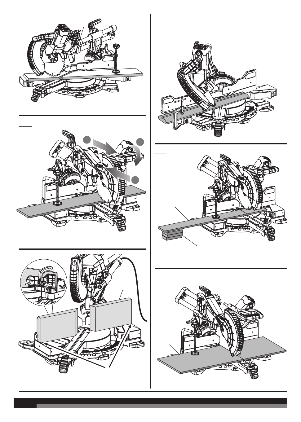
USING THE DEPTH GUIDE
See figure 3.
When used, the depth guide limits the downward travel of the blade
when cutting dadoes and other non-through cuts.
To use the depth guide:
Ŷ Unplug the saw.
Ŷ Rotate the depth stop outward.
Ŷ Loosen the lock nut.
Ŷ With the depth control knob touching the depth stop, adjust the
depth control knob by turning the knob until the desired depth
of cut is attained.
Ŷ Tighten the lock nut.
Ŷ A wooden spacer must be placed between the workpiece and
the fence to create a distance of 90 mm inches between the
workpiece and the fence for a consistent depth of cut in the
workpiece. Use the work clamp to clamp the spacer and another
suitable clamp to clamp the workpiece. Make the slide cut at the
desired depth. See Figures 34 and 35.
Ŷ Rotate the depth stop inward for normal through cuts.
NOTE: The depth stop must be pushed in before locking/unlocking
the saw arm.
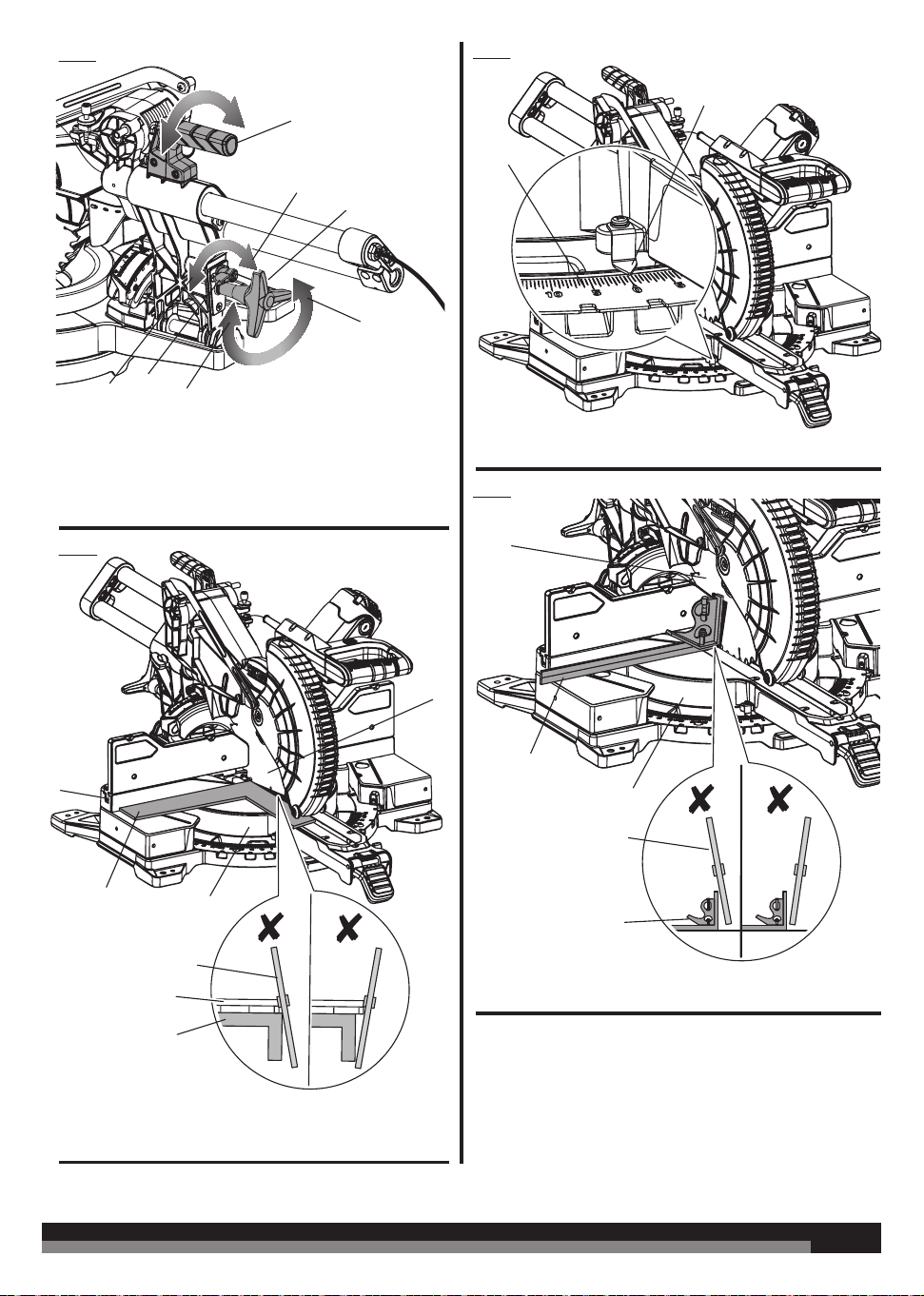
LOCKING/UNLOCKING THE SAW ARM
See figure 4.
When locking and unlocking the saw arm, it is not necessary to loosen
the depth control knob. However, the depth stop must be pushed in.
To unlock and raise the saw arm:
Ŷ Firmly grasp the “D” handle and apply downward pressure while
at the same time pulling the head lock pin out and away from the
saw housing.
Ŷ Release the head lock pin and slowly raise the saw arm.
To lock the saw arm:
Ŷ Firmly grasp the “D” handle and apply downward pressure until
head stops. Push in the head lock pin toward the saw.
Ŷ Release the head lock pin allowing it to lock the saw into place.
NOTE: Do not use saw to cut while in the locked position.
DUST BAG AND FRAME ASSEMBLY
See figure 5.
To install the dust bag and frame assembly, slide the open end of the
frame assembly onto the exhaust port.
For eicient operation, empty the dust bag before it is half full. This
will permit better air flow through the bag.
INSTALLING/REPLACING THE BLADE
See figure 6.
WARNING! Before removing and fitting the blade, make sure to
wear safety gloves.
WARNING! A 254 mm (10 in.) blade is the maximum blade
capacity of the product. Never use a blade that is too thick to allow
outer flange to engage with the flats on the spindle. Larger blades
will come in contact with the blade guards, while thicker blades will
prevent the blade bolt from securing the blade on the spindle. Either
of these situations could result in a serious accident and can cause
serious personal injury.
WARNING! Only use the blade specified in this manual and its
speed is at least equal to the speed marked on the product.
Ŷ Unplug the saw.
Ŷ Raise the saw arm.
Ŷ Rotate the lower blade guard to expose the blade bolt.
Ŷ Depress the spindle lock button and rotate the blade bolt until
the spindle locks.
Ŷ Using the hex end of the blade wrench, loosen and remove the
blade bolt from the arbor.

18
18
NOTE: The blade bolt has left hand threads. Turn blade bolt
clockwise to loosen.
Ŷ Remove the outer blade washer.
NOTE: The inner blade washer is integrated into the spindle and
cannot be removed.
Ŷ Wipe a drop of oil onto inner blade washer and outer blade
washer where they contact the blade.
Ŷ Rotate the lower blade guard to expose the arbor.
Ŷ Fit saw blade inside blade guard and onto the arbor and against
the inner blade washer. The blade teeth point downward at the
front of saw as shown.
Ŷ Replace the outer blade washer. The double “D” flats on the blade
washers align with the flats on the spindle.
Ŷ Depress spindle lock button and replace blade bolt.
NOTE: The blade bolt has left hand threads. Turn blade bolt
counterclockwise to tighten.
WARNING! Always install the blade with the blade teeth and the
arrow printed on the side of the blade pointing down at the front of
the saw. The direction of blade rotation is also stamped with an arrow
on the upper blade guard.
Ŷ Tighten the blade bolt securely.
Ŷ Lower the blade guard.
Ŷ Raise and lower the saw arm to ensure the lower blade guard
functions correctly.
WARNING! Make sure the spindle lock button is not engaged
before reconnecting saw into power source. Never engage spindle
lock button when blade is rotating.
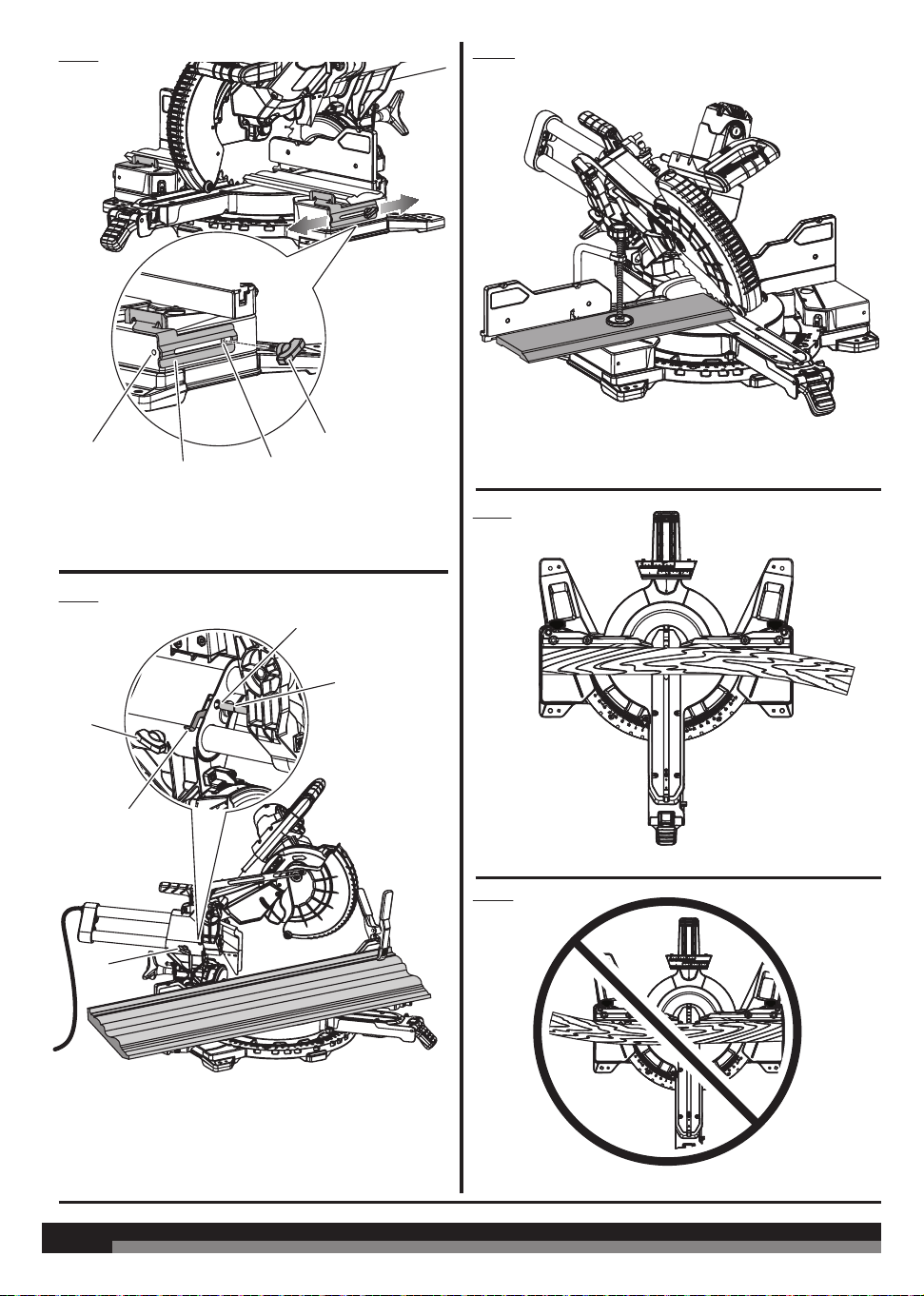
REMOVING/REPLACING THE ADJUSTABLE THROAT PLATES
See figures 7.
When squaring the saw blade, it may be necessary to move the
throat plate away from the blade. Once the saw’s alignment has
been confirmed, return the throat plate to its original position. Never
operate the saw without a throat plate installed.
Ŷ Unplug the saw.
Ŷ Using the blade wrench provided, loosen the screws securing the
right side of the adjustable throat plate.
NOTE: The throat plate may be adjusted to (near) zero clearance
to support thin materials.
Ŷ Slide the throat plate away from the blade as far as possible.
Ŷ Retighten the screws, being careful not to overtighten which can
cause the throat plate to bow or bend.
Ŷ Repeat the above steps for the left side of the throat plate.
Ŷ Visually inspect and make sure that the throat plates fit flush with
the tuning table.
INSTALLING THE WORK CLAMP
See figure 8.
WARNING! In some operations, the work clamp assembly may
interfere with the operation of the blade guard assembly. Always make
sure there is no interference with the blade guard prior to beginning
any cutting operation to reduce the risk of serious personal injury.
The work clamp provides greater control by clamping the workpiece
to the mitre table. It also helps to prevent the workpiece from creeping
toward the saw blade. This is helpful when cutting compound mitres.
Depending on the cutting operation and the size of the workpiece,
it may be necessary to use a C-clamp instead of the work clamp to
secure the workpiece prior to making the cut. The work clamp can be
installed and used on either side of the blade.
To install the work clamp:
Ŷ Place the work clamp shaft in one of the holes located behind the
sliding mitre fence.
Ŷ Rotate the knob on the work clamp to move it up or down as
needed.
ADJUSTING THE MITRE LOCK
See figure 9 - 10.
Prior to squaring the saw blade to the fence, ensure the mitre table
moves and locks securely.
Ŷ Unplug the saw.
Ŷ Locate the mitre lock nut, mitre lock screw and mitre lock shoe on
the rear underside of the saw.
To check the clamping force of the mitre lock:
Ŷ Unplug the saw.
Ŷ Lift the mitre lock lever and press the mitre detent bypass button
to unlock the mitre table.
Ŷ Rotate the mitre table to an “unindexed” mitre position other than
0˚, 15˚, 22.5˚, 31.6˚, 45˚, 60˚, and 67.5˚.
Ŷ Push the mitre lock lever down and attempt to move the mitre
table. If the table moves easily when in the “locked” position,
adjust the mitre lock screw.
Ŷ Using a 4 mm hex key, adjust the mitre lock screw. Make
adjustments of one-quarter turn or less.
NOTE: Turning the mitre lock screw clockwise will increase the
clamping force. Turning the mitre lock screw counterclockwise
decreases the clamping force.
Ŷ After making the adjustment, test the clamping force.
To adjust mitre table movement:
Ŷ Lift the mitre lock lever, press the mitre detent bypass button, and
move the mitre table left to right. If the mitre table does not move
freely, adjust the mitre lock nut.
Ŷ Using the 4 mm hex key, hold the mitre lock screw stationary and
use the 13 mm combination wrench to adjust the nut holding the
mitre lock shoe.
NOTE: Turning the mitre lock nut clockwise will move the shoe
closer to the mitre saw base and make it harder to move the mitre
table. Turning the mitre lock nut counterclockwise will move the
shoe farther away from the base and make it easier to move the
table.
Ŷ Adjust the mitre lock nut until the shoe and mitre saw base are
close but not in contact with each other.
Ŷ After making the adjustment, test the movement of the mitre
table.
Ŷ Rotate the mitre table to an “unindexed” mitre position other than
0˚, 15˚, 22.5˚, 31.6˚, 45˚, 60˚, and 67.5˚ and push the mitre lock
lever down. Test the clamping force.
NOTE: It should take considerable force to move the table in the
locked position.
ADJUSTING THE MITRE LOCK LEVER
See figure 11.
Ŷ Unplug the saw.
Ŷ Lift the mitre lock lever to unlock the mitre table.
Ŷ If the mitre lock lever is not parallel with the top of the mitre table,
adjustments are needed.
Ŷ Using a 10 mm combination wrench and a flat head screwdriver,
hold the mitre lock screw in place and loosen the mitre lock nut.
Ŷ Turn the mitre lock screw clockwise to lower the lever.
Ŷ Turn the mitre lock screw counterclockwise to raise the lever.
Ŷ Continue to adjust the lock lever until it is parallel with the mitre
table.
Ŷ Hold the screw in place and tighten the lock nut securely.
SQUARING THE SAW BLADE TO THE FENCE
See figures 12 - 15.
Ŷ Disconnect the mains supply from the product.

19
19
Ŷ Pull the saw arm all the way down and lock in transport position.
Ŷ Loosen the bevel lock knob and disengage the bevel detent lever.
Ŷ Set the saw at the 0º bevel angle, engage the bevel detent lever,
and ensure the saw engages the detent.
Ŷ Tighten the bevel lock knob.
Ŷ Lift the mitre lock lever to unlock the mitre table.
Ŷ Press the mitre detent button and rotate the mitre table until the
pointer on the mitre scale is positioned at 0°.
Ŷ Release the mitre detent button and allow the mitre table to
engage the 0° detent position.
Ŷ Push the mitre lock lever down to lock the mitre table.
Ŷ Lay a framing square flat on the mitre table. Place one leg of the
square against the fixed fence. Slide the other leg of the square
against the flat part of the saw blade.
NOTE: Make sure that the square contacts the flat part of the saw
blade, not the blade teeth.
Ŷ The edge of the square and the saw blade should be parallel.
Ŷ If the front or back edge of the saw blade angles away from the
square as shown in figure 14, adjustments are needed.
Ŷ Rotate the extension tables to their fully extended position. See
“To Make Extended Mitre Cuts” later in this manual.
Ŷ Lift the mitre lock lever to unlock the mitre table.
Ŷ Press the mitre detent bypass button. Rotate the mitre table until
the pointer is at the left 15° position on the mitre scale.
Ŷ Using a 4 mm hex key, loosen the 5 screws that hold the mitre
scale/detent plate in place.
Ŷ Rotate the mitre table to the 0° position on the mitre scale and
detent engages in the detent plate.
Ŷ Rotate the mitre table until the blade is parallel with the framing
square.
Ŷ Push the mitre lock lever down to lock the mitre table.
Ŷ Tighten the 4 visible screws that secure the mitre scale/detent
plate.
Ŷ Lift the mitre lock lever to unlock the mitre table.
Ŷ Press the mitre detent bypass button. Rotate the mitre table until
the pointer is at the left 15° position on the mitre scale.
Ŷ Tighten the remaining screw to secure the mitre scale/detent
plate.
SQUARING THE BLADE TO THE MITRE TABLE
See figures 16.
Ŷ Unplug the saw.
Ŷ Pull the saw arm all the way down and lock in transport position.
Ŷ Lift the mitre lock lever to unlock the mitre table.
Ŷ Press the mitre detent bypass half way and rotate the mitre table
until the pointer on the mitre scale is positioned at 0°.
Ŷ Release the mitre detent bypass and allow the mitre table to
engage the 0° detent position.
Ŷ Push the mitre lock lever down to lock the mitre table.
Ŷ Loosen the bevel lock knob and disengage the bevel detent lever.
Ŷ Set the saw at the 0º bevel angle, engage the bevel detent lever
and ensure the saw engages the detent.
Ŷ Tighten the bevel lock knob.
Ŷ Place a combination square against the mitre table and the flat
part of the saw blade.
NOTE: Make sure that the square contacts the flat part of the saw
blade, not the blade teeth.
Ŷ Rotate the blade by hand and check the blade-to-table alignment
at several points.
Ŷ The edge of the square and the saw blade should be parallel.
Ŷ If the top or bottom of the saw blade angles away from the square
as shown in figure 16, adjustments are needed.
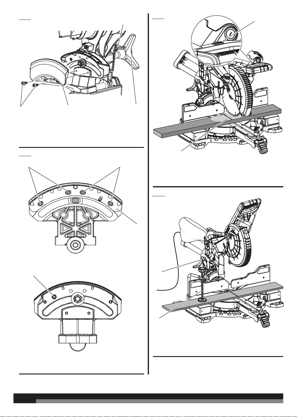
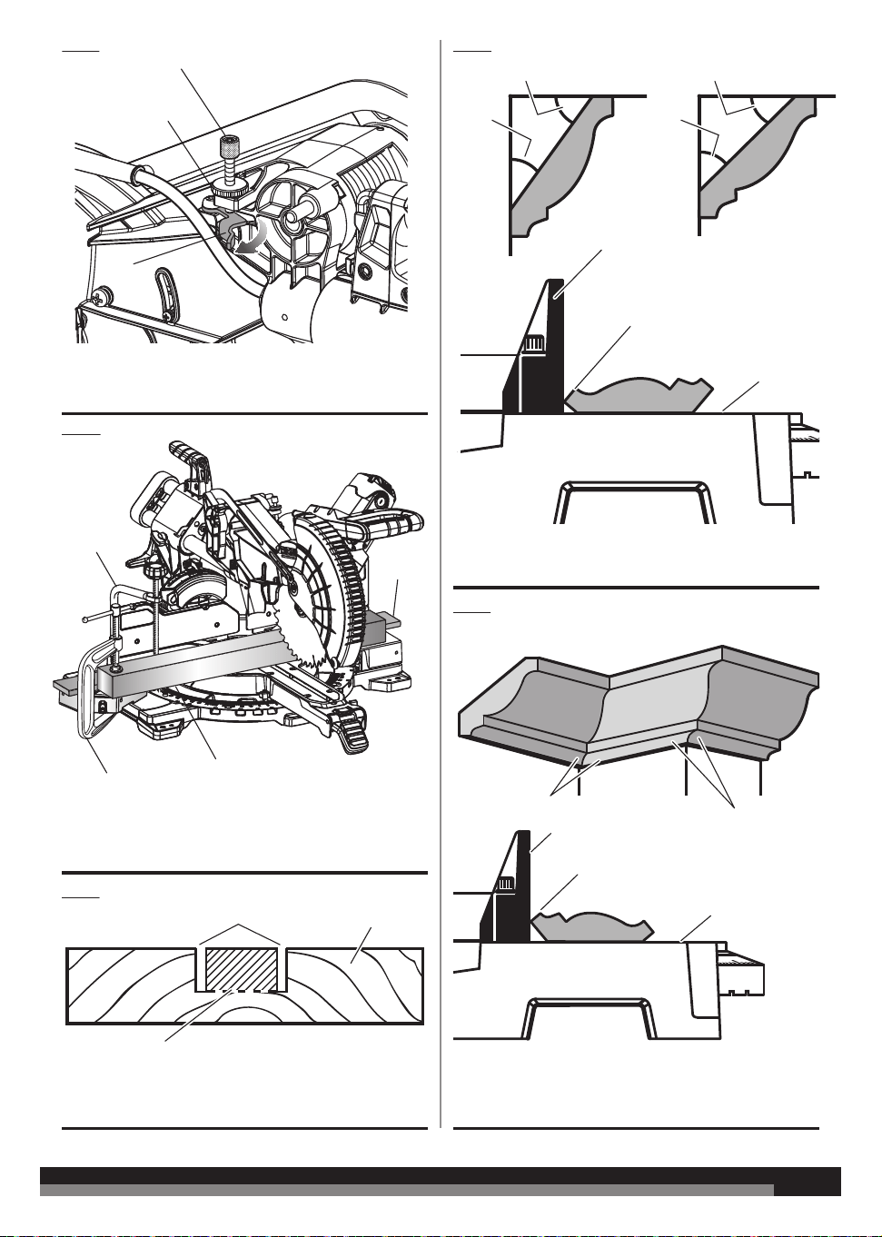
TO ADJUST THE BEVEL
See figures 17 - 18.
Ŷ Remove the bevel lock dust cover.
Ŷ Move the bevel detent lever to the detent disengaged position.
Ŷ Set the bevel at any angle that allows access to the 4 screws on
the back of the bevel lock bracket.
Ŷ Tighten the bevel lock knob.
Ŷ Using a 4 mm hex wrench, loosen the 4 screws that hold the bevel
detent plate in place. Do not remove the screws.
Ŷ Loosen the bevel lock knob and move the bevel detent lever to
the detent disengaged position.
Ŷ Set the bevel angle at 0°.
Ŷ Move the bevel detent lever to the detent engaged position.
Ŷ Check the 0° angle using a combination square.
Ŷ If adjustment is needed, use a 4 mm hex key to turn the micro
adjust screw on the front of the bevel lock bracket to adjust the
saw to the 0° bevel angle.
Ŷ Tighten the bevel lock knob.
Ŷ Tighten the 2 outermost screws that retain the bevel detent plate.
Ŷ Loosen the bevel lock knob and set the bevel at any angle that
allows access to the 2 remaining screws on the back of the bevel
lock bracket.
Ŷ Tighten the bevel lock knob.
Ŷ Tighten the remaining 2 screws that retain the bevel detent plate.
Ŷ Replace the bevel lock dust cover and tighten the screws securely.
OPERATION
WARNING! Do not allow familiarity with products to make you
careless. Remember that a careless fraction of a second is suicient
to inflict severe injury.
WARNING! Always wear eye protection with side shields. Failure
to do so could result in objects being thrown into your eyes, resulting
in possible serious injury.
WARNING! Do not use any attachments or accessories not
recommended by the manufacturer of the product. The use of
attachments or accessories not recommended can result in serious
personal injury.
WARNING! To avoid serious personal injury, always push the
mitre lock lever down and tighten the bevel lock knob securely before
making a cut. Failure to do so could result in movement of the control
arm or mitre table while making a cut.
WARNING! To avoid serious personal injury, keep your hands
outside the no hands zone, at least 100 mm from blade. Never
perform any cutting operation freehand (without holding workpiece
against the fence). The blade could grab the workpiece if it slips or
twists.
WARNING! Before starting any cutting operation, clamp or bolt
your mitre saw to a workbench or leg stand. Never operate your mitre
saw on the floor or in a crouched position. Failure to heed this warning
can result in serious personal injury.
WARNING! Do not start your compound mitre saw without
checking for interference between the blade and the mitre fence.
Damage could result to the blade if it strikes the mitre fence during
operation of the saw. Failure to heed this warning can also result in
serious personal injury.
CUTTING WITH YOUR SLIDING COMPOUND MITRE SAW
WARNING! When using a work clamp or C-clamp to secure
your workpiece, clamp workpiece on one side of the blade only. The
workpiece must remain free on one side of the blade to prevent the
blade from binding in workpiece. The workpiece binding the blade
will cause motor stalling and kickback. This situation could cause an
accident resulting in possible serious personal injury.
WARNING! Never move the workpiece or make adjustment to

20
20
any cutting angle while the saw is running and the blade is rotating.
Any slip can result in contact with the blade causing serious personal
injury.
WARNING! Do not try to cut narrow pieces using the sliding
feature. Failure to heed this warning could result in serious personal
injury.
LED LIGHTING SYSTEM
See figure 19.
The LED lighting system casts the shadow of the blade onto the
workpiece. This results in greater accuracy of cuts and requires no
adjustments.
To use this feature, turn the LED switch on.
Bring the saw arm down so the blade is approximately 10 mm from
the workpiece. The shadow of the blade will be projected onto the
workpiece, indicating where the blade teeth will make contact as the
cut is made.
WARNING! Do not stare at the LED light when it is switched on.
TO MAKE NON-SLIDING CUTS
WARNING! Securely tighten the slide lock knob when making any
non-sliding cuts. Failure to tighten the knob could result in the saw
head moving during the cutting operation.
TO MITRE CUT/CROSS CUT
See figure 20 - 21.
A cross cut is made by cutting across the grain of the workpiece. A
straight cross cut is made with the mitre table set at the 0° position.
Mitre cross cuts are made with the mitre table set at some angle other
than 0°.
Ŷ Slide the saw head to its most rearward position and tighten the
slide lock knob securely.
Ŷ Pull out the head lock pin and lift saw arm to its full height.
To move the mitre table to any of the indexed mitre stops (0°,
15°, 22.5°, 31.6°, 45°, 60° and 67.5° left or right):
Ŷ Move the mitre table to an indexed mitre stop position and
release mitre detent bypass button. The mitre table will click into
place when it reaches an indexed stop.
Ŷ Push the mitre lock lever down to lock the mitre table.
To move the mitre table to any desired position on the mitre
scale:
Ŷ Lift the mitre lock lever, then press the mitre detent bypass
button. The mitre table will move freely left or right.
Ŷ Push the mitre lock lever down to lock the mitre table.
Ŷ Place the workpiece flat on the mitre table with one edge securely
against the fence. If the board is warped, place the convex side
against the fence. If the concave edge of a board is placed against
the fence, the board could collapse on the blade at the end of the
cut, jamming the blade. See Figures 41 - 42.
Ŷ When cutting long pieces of lumber or molding, support the
opposite end of the workpiece with a roller stand or with a work
surface level with the saw table. See Figure 31.
Ŷ Align cutting line on the workpiece with the edge of saw blade.
Ŷ Turn the LED switch on to project the blade shadow onto the
workpiece.
Ŷ Grasp the workpiece firmly with one hand and secure it against
the fence. Use the work clamp or a C-clamp to secure the
workpiece when possible.
Ŷ Before turning on the saw, perform a dry run of the cutting
operation to make sure that no problems will occur when the cut
is made.
Ŷ Grasp the saw handle firmly. Turn the switch on and allow several
seconds for the blade to reach maximum speed.
Ŷ Slowly lower the blade into and through the workpiece.
Ŷ Release the switch trigger and allow the saw blade to stop
rotating before raising the blade out of workpiece and removing
the workpiece from the mitre table.
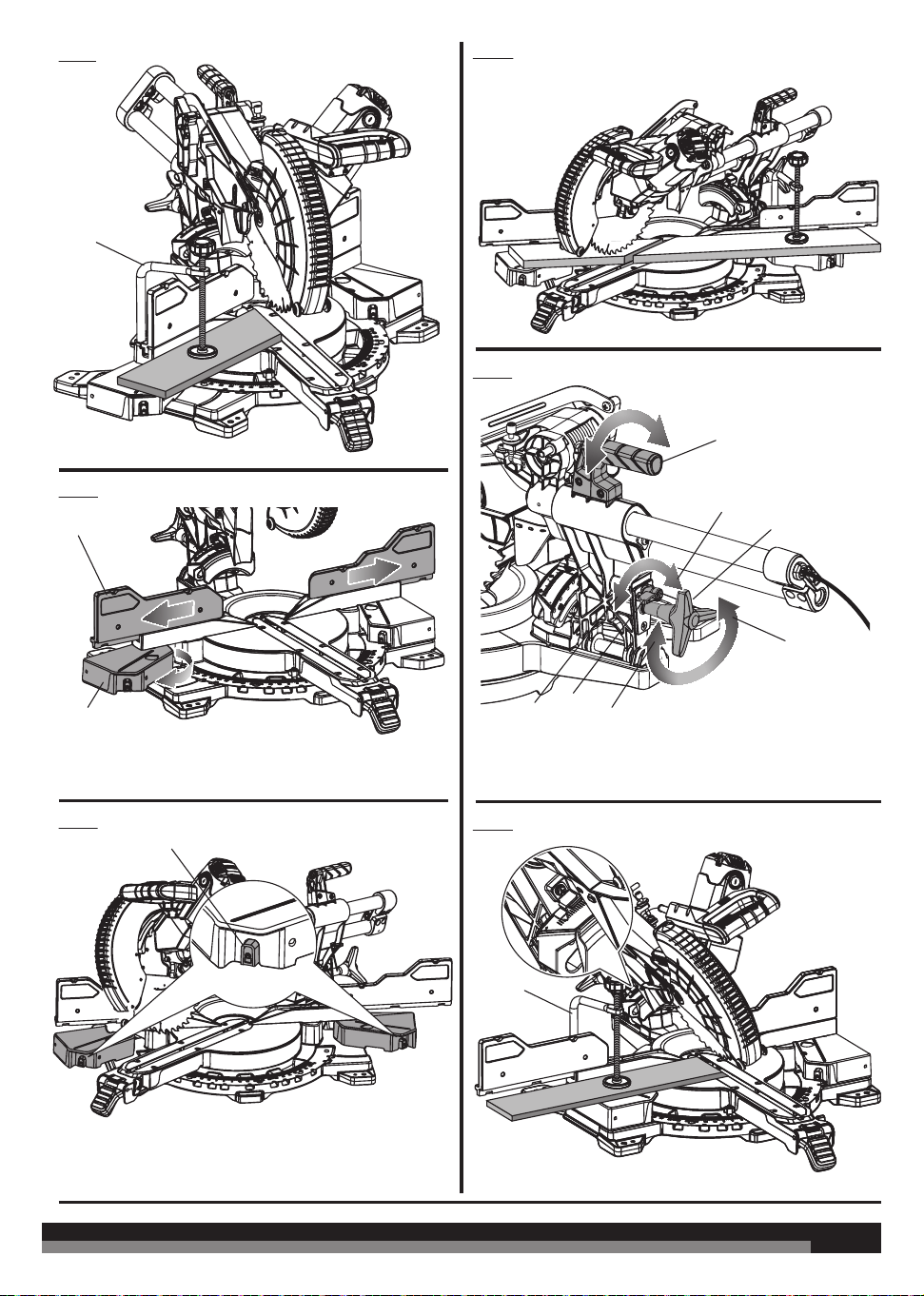
TO MAKE EXTENDED MITRE CUTS
See figure 22 - 24.
The extended mitre capacity of the saw allows you to make mitre cuts
up to 70°. Using the mitre extension tables, you can cut 22.5° mitres
for acute 45° corners.
WARNING! When performing 70° mitre cut, only 0° bevel
angle is allowed.
The rotating extension tables can be set to one of three positions,
depending on the desired type of cut.
WARNING! Do not set the extension tables to the unlocked
positions. Set to one of the three locked positions only.
Use the rotating extension tables when making mitre cuts greater
than 45°.
Ŷ Slide the saw head to its most rearward position and tighten the
slide lock knob securely.
Ŷ Pull out the head lock pin and lift saw arm to its full height.
Ŷ Slide out the fence on the side opposite of where the cut will be
made. This ensures that the bevel lock bracket will not bump
against the fence when setting the blade for extended mitre cuts.
Ŷ To rotate the extension tables outward, press the table lock
button and select one of the preset positions.
Ŷ Release the table lock button and move the table until it locks
into position.
Ŷ Lift the mitre lock lever to unlock the mitre table and press the
detent bypass button. Rotate the mitre table until the pointer
aligns with the desired angle on the mitre scale.
Ŷ Push the mitre lock lever down to lock the mitre table.
Ŷ Align cutting line on the workpiece with the edge of saw blade.
Ŷ Turn the LED switch on to project the blade shadow onto the
workpiece.
WARNING! For extended mitre cuts, place the clamp on the large
mitre angle side of the table. Clamping or holding the workpiece on
the small mitre angle side of the table may place your hand too close
to the blade and cause serious personal injury.
Ŷ Grasp the workpiece firmly with one hand and secure it against
the fence. Use the work clamp or a C-clamp to secure the
workpiece when possible.
Ŷ Before turning on the saw, perform a dry run of the cutting
operation to make sure that no problems will occur when the cut
is made.
Ŷ Grasp the saw handle firmly. Turn on the switch and allow several
seconds for the blade to reach maximum speed.
Ŷ Slowly lower the blade into and through the workpiece.
Ŷ Release the switch trigger and allow the saw blade to stop rotating
before raising the blade out of the workpiece and removing the
workpiece from the mitre table.
TO BEVEL CUT
See figure 25 - 26.
A bevel cut is made by cutting across the grain of the workpiece with
the blade angled to the workpiece. A straight bevel cut is made with
the mitre table set at the zero degree position and the blade set at
an angle.
Bevel cuts may be made by angling the blade to the left or right.
NOTE: It may be necessary to adjust or remove the sliding mitre
fence to insure proper clearance prior to making the cut. Make sure
the fence lock knob is tightened securely to avoid interference with
the saw head.
Ŷ Make sure the slide lock knob is tightened securely.
Ŷ Pull out the head lock pin and lift saw arm to its full height.
Ŷ Lift the mitre lock lever and press the mitre detent bypass button.
Set the mitre table to zero.
Ŷ Push the mitre lock lever down to lock the mitre table.

21
21
Ŷ Loosen the bevel lock knob.
NOTE: Firmly grasp the “D” handle while loosening the bevel lock
knob to prevent the saw head from shifting unexpectedly.
Ŷ Move the bevel detent lever to the detent engaged position to
select one of the preset bevel settings or place the bevel detent
lever in the detent disengaged position to select any desired
setting.
NOTE: Indexed bevel positions are located at 0°, 15°, 22.5°, 33.9°,
and 45° left or right.
Ŷ Tighten the bevel lock knob.
Ŷ Place the workpiece flat on the mitre table with one edge securely
against the fence. If the board is warped, place the convex side
against the fence. If the concave edge of a board is placed against
the fence, the board could collapse on the blade at the end of the
cut, jamming the blade. See Figures 41 - 42.
Ŷ When cutting long pieces of lumber or molding, support the
opposite end of the workpiece with a roller stand or with a work
surface level with the saw table. See Figure 31.
Ŷ Grasp the workpiece firmly with one hand and secure it against
the fence. Use the work clamp or a C-clamp to secure the
workpiece when possible.
Ŷ Before turning on the saw, perform a dry run of the cutting
operation to make sure that no problems will occur when the cut
is made.
Ŷ Align cutting line on the workpiece with the edge of saw blade.
Ŷ Turn the LED switch on to project the blade shadow onto the
workpiece.
Ŷ Grasp the saw handle firmly. Turn on the saw and allow several
seconds for the blade to reach maximum speed.
Ŷ Slowly lower the blade into and through the workpiece.
Ŷ Release the switch trigger and allow the saw blade to stop rotating
before raising the blade out of the workpiece and removing the
workpiece from the mitre table.
TO COMPOUND MITRE CUT
See figure 27.
A compound mitre cut is a cut made using a mitre angle and a bevel
angle at the same time. This type of cut is used to make picture
frames, cut molding, make boxes with sloping sides, and for certain
roof framing cuts.
To make this type of cut the control arm on the mitre table must
be rotated to the correct angle and the saw arm must be tilted to
the correct bevel angle. Care should always be taken when making
compound mitre setups due to the interaction of the two angle
settings.
Adjustments of mitre and bevel settings are interdependent with one
another. Each time you adjust the mitre setting you change the eect
of the bevel setting. Also, each time you adjust the bevel setting you
change the eect of the mitre setting.
It may take several settings to obtain the desired cut. The first angle
setting should be checked after setting the second angle, since
adjusting the second angle aects the first.
Once the two correct settings for a particular cut have been obtained,
always make a test cut in scrap material before making a finish cut in
good material.
NOTE: It may be necessary to adjust or remove the sliding mitre
fence to insure proper clearance prior to making the cut. Make sure
the fence lock knob is tightened securely to avoid interference with
the saw head.
Ŷ Slide the saw head to its most rearward position and tighten the
slide lock knob securely.
Ŷ Pull out the lock pin and lift saw arm to its full height.
Ŷ Lift the mitre lock lever and depress the detent release button to
release the mitre table.
Ŷ Rotate the control arm until the scale indicator aligns with the
desired angle on the mitre scale.
NOTE: When performing 45° bevel compound cut, the maximum
mitre angle is 45°. When performing 70° mitre cut, only 0° bevel
angle is allowed.
Ŷ Release the detent release button, then push the mitre lock lever
down to secure the mitre table.
Ŷ Loosen the bevel lock knob.
NOTE: Firmly grasp the “D” handle while loosening the bevel lock
knob to prevent the saw head from shifting unexpectedly.
Ŷ Move the bevel detent lever to the detent engaged position to
select one of the preset bevel settings or place the bevel detent
lever in the detent disengaged position to select any desired
setting.
NOTE
: Indexed bevel positions are located at 0°, 15°, 22.5°, 33.9°,
and 45° left or right.
Ŷ Tighten the bevel lock knob.
Ŷ Recheck mitre angle setting. Make a test cut in scrap material.
Ŷ Place the workpiece flat on the mitre table with one edge securely
against the fence. If the board is warped, place the convex side
against the fence. If the concave edge of a board is placed against
the fence, the board could collapse on the blade at the end of the
cut, jamming the blade. See Figures 41 - 42.
Ŷ When cutting long pieces of lumber or molding, support the
opposite end of the workpiece with a roller stand or with a work
surface level with the saw table. See Figure 31.
Ŷ Grasp the workpiece firmly with one hand and secure it against
the fence. Use the work clamp or a C-clamp to secure the
workpiece when possible.
Ŷ Before turning on the saw, perform a dry run of the cutting
operation to make sure that no problems will occur when the cut
is made.
Ŷ Align cutting line on the workpiece with the edge of saw blade.
Ŷ Turn the LED switch on to project the blade shadow onto the
workpiece.
Ŷ Make a test cut in scrap material.
Ŷ Grasp the saw handle firmly. Turn the saw on and allow several
seconds for the blade to reach maximum speed.
Ŷ Slowly lower the blade into and through the workpiece.
Ŷ Release the switch trigger and allow the saw blade to stop
rotating before raising the blade out of workpiece and removing
the workpiece from the mitre table.
WARNING! Never make a cut by pulling the saw toward you as
the blade can climb on top of the workpiece and come toward you.
Failure to heed this warning could result in serious personal injury.
TO SLIDE CUT
See figure 28.
The sliding feature will cut nominal workpieces 305 mm wide by 38
mm thick or 152 mm wide by 89 mm thick.
With the saw o, pull the saw arm forward. Turn the saw on (let
blade reach maximum speed), push the blade down cutting into the
workpiece then back toward the rear of the saw to make a cut. Cuts
are made by pushing the saw blade away from you and toward the
bevel scale at the back of the saw stopping when the full rear position
has been reached after each cut. When the saw is running (turned on),
Never pull the saw blade toward you or toward the front of the saw.
Ŷ Pull out the head lock pin and lift saw arm to its full height.
Ŷ Place the workpiece flat on the mitre table with one edge securely
against the fence. If the board is warped, place the convex side
against the fence. If the concave edge of a board is placed against
the fence, the board could collapse on the blade at the end of the
cut, jamming the blade. See Figures 41 - 42.
Ŷ When cutting long pieces of lumber or molding, support the
opposite end of the workpiece with a roller stand or with a work
surface level with the saw table. See Figure 31.
Ŷ Align the cutting line on the workpiece with the edge of saw blade.

22
22
Ŷ Turn the LED switch on to project the blade shadow onto the
workpiece.
Ŷ Loosen the slide lock knob by turning the knob counterclockwise.
Ŷ Grasp the workpiece firmly with one hand and secure it against
the fence. Use the work clamp or a C-clamp to secure the
workpiece when possible.
Ŷ Before turning on the saw, perform a dry run of the cutting
operation to make sure that no problems will occur when the cut
is made.
Ŷ With the saw off, grasp the saw handle firmly then pull the saw
forward until the blade arbor (center of the saw blade) is over the
front of the workpiece.
Ŷ Turn the saw on and allow several seconds for the blade to reach
maximum speed.
Ŷ Slowly lower the blade into and through the front edge of the
workpiece.
Ŷ Push the saw handle away from you and toward the bevel scale
at the back of the saw.
Ŷ Release the switch trigger and allow the saw blade to stop
rotating before raising the blade out of workpiece and removing
the workpiece from mitre table.
MAKING AN AUXILIARY FENCE
See figure 29.
Depending on the size and position of the workpiece, certain unusual
cuts may benefit from the additional support that can be provided
by an auxiliary fence. The holes provided in the mitre fence are used
to secure an auxiliary fence in place. To make an auxiliary fence, we
recommend using two pieces of wood 10 mm thick, 90 mm. high, and
250 mm. long.
NOTE: The auxiliary fence can only be used when the bevel is set at
0°. When making a bevel cut, the auxiliary fence must be removed.
To attach the auxiliary fence to the saw:
Ŷ Make sure the fence lock knob is tightened securely.
Ŷ Place the 250 mm. long piece of wood against the mitre fence and
aligned with the left edge of the mitre table.
Ŷ Clamp the wood tightly against the fence and drive wood screws
from the back of the fence through the two holes and into the
auxiliary fence. If necessary, drill a pilot hole into wood first to
prevent splitting. Remove clamp when finished.
NOTE: Make sure the screws you use to attach the auxiliary fence
do not pass through the front face of the fence and the length of
the screws will not put them in the path of the blade at any angle.
Ŷ Make full 45° left and right mitre cuts through the auxiliary fence.
NOTE: Check for interference between the auxiliary fence and the
lower blade guard. Correct any interference before proceeding.
Ŷ Repeat steps with second board by aligning with right side of
mitre table.
WARNING! Both sides of the auxiliary fence must be aligned on
the same plane.
WARNING! When using an auxiliary fence, check and ensure that
there is no interference with any part of the saw during operation.
SUPPORTING LONG WORKPIECES
See figure 30 - 31.
Long workpieces need extra support. Supports should be placed
along the workpiece so it does not sag. The support should let the
workpiece lay flat on the base of the saw and mitre table during the
cutting operation. Use the work clamp or a C-clamp to secure the
workpiece.
NOTE: When making a compound mitre cut as shown in figure 30,
it may be necessary to adjust or remove the sliding mitre fence to
ensure proper clearance prior to making the cut. Make sure the fence
lock knob is tightened securely to avoid interference with the saw
head.
CLAMPING WIDE WORKPIECES
See figure 32.
When cutting wide workpieces, such as a nominal 50 mm. x 50 mm,
boards should be clamped securely.
WARNING! Never make a cut by pulling the saw toward you as
the blade can climb on top of the workpiece and come toward you.
Failure to heed this warning could result in serious personal injury.
ROUGH CUTTING A DADO
See figure 33 - 35.
Using a wood chisel and the depth control knob, it is possible to make
a rough dado cut. Always make a practice cut on scrap wood.
To use the depth control knob:
Ŷ Unplug the saw.
Ŷ Rotate the depth stop outward.
Ŷ Loosen the lock nut.
Ŷ With the depth control knob touching the depth stop, adjust the
depth control knob by turning the knob until the desired depth
of cut is attained.
Ŷ Tighten the lock nut.
Ŷ A wooden spacer must be placed between the workpiece and the
fence to create a distance of 3-1/2 inches between the workpiece
and the fence for a consistent depth of cut in the workpiece. Use
the work clamp to clamp the spacer and another suitable clamp
to clamp the workpiece. Make the slide cut at the desired depth.
Ŷ Rotate the depth stop inward for normal through cuts.
NOTE: The depth stop must be pushed in before locking/
unlocking the saw arm.
To make the cut:
Ŷ Unlock the slide lock knob.
Ŷ Pull out the head lock pin and lift saw arm to its full height.
Ŷ With the saw off, pull the saw arm forward. Turn the saw on (let
blade reach maximum speed), then push the blade down on top
of the workpiece then back toward the rear of the saw to make
a cut.
Ŷ Cut two outside grooves in the workpiece.
Ŷ Using a wood chisel, remove the material between the two
outside grooves.
CUTTING CROWN MOLDING
The compound mitre saw does an excellent job of cutting crown
molding. In general, compound mitre saws do a better job of cutting
crown molding than any other tool.
In order to fit properly, crown molding must be compound mitred with
extreme accuracy.
The two contact surfaces on a piece of crown molding that fit flat
against the ceiling and the wall of a room are at angles that, when
added together, equal exactly 90°. Most crown molding has a top rear
angle (the section that fits flat against the ceiling) of 52° and a bottom
rear angle (the section that fits flat against the wall) of 38°.
LAYING MOLDING FLAT ON THE MITRE TABLE
See figure 36 - 37.
To use this method for accurately cutting crown molding for a 90°
inside or outside corner, lay the molding with its broad back surface
flat on the mitre table and against the fence.
When setting the bevel and mitre angles for compound mitres,
remember that the settings are interdependent; changing one angle
changes the other angle as well.
Keep in mind that the angles for crown molding are very precise
and diicult to set. Since it is very easy for these angles to shift, all
settings should first be tested on scrap molding. Also most walls do
not have angles of exactly 90°; therefore, you will need to fine tune
your settings.

23
23
When cutting crown molding by this method the bevel angle should
be set at 33.9°. The mitre angle should be set at 31.6° either right or
left, depending on the desired cut for the application. See the chart
below for correct angle settings and correct positioning of crown
molding on mitre table.
The settings in the chart below can be used for cutting crown molding
with 52° and 38° angles or 45° and 45° angles. The crown molding is
placed flat on the mitre table using the compound features of the
product.
Type of
crown
molding
Bevel angle
type of cut
Setting
38
o
33.9
o
(Left) Left side of inside corner
1. Top edge of molding against fence
2. Mitre table set right 31.6
o
3. Save left end of cut
38
o
33.9
o
(Left) Right side of inside corner
1. Bottom edge of molding against
fence
2. Mitre table set left 31.6
o
3. Save left end of cut
38
o
33.9
o
(Left) Left side of outside corner
1. Bottom edge of molding against
fence
2. Mitre table set left 31.6
o
3. Save right end of cut
38
o
33.9
o
(Left) Right side of outside corner
1. Top edge of molding against fence
2. Mitre table set right 31.6
o
3. Save right end of cut
38
o
33.9
o
(Right) Left side of inside corner
1. Bottom edge of molding against
fence
2. Mitre table set right 31.6
o
3. Save right end of cut
38
o
33.9
o
(Right) Right side of inside corner
1. Top edge of molding against fence
2. Mitre table set left 31.6
o
3. Save right end of cut
38
o
33.9
o
(Right) Left side of outside corner
1. Top edge of molding against fence
2. Mitre table set left 31.6
o
3. Save left end of cut
38
o
33.9
o
(Right) Right side of outside corner
1. Bottom edge of molding against
fence
2. Mitre table set right 31.6
o
3. Save left end of cut
45
o
30
o
(Left) Left side of inside corner
1. Top edge of molding against fence
2. Mitre table set right 35.3
o
3. Save left end of cut
45
o
30
o
(Left) Right side of inside corner
1. Bottom edge of molding against
fence
2. Mitre table set left 35.3
o
3. Save left end of cut
45
o
30
o
(Left) Left side of outside corner
1. Bottom edge of molding against
fence
2. Mitre table set left 35.3
o
3. Save right end of cut
45
o
30
o
(Left) Right side of outside corner
1. Top edge of molding against fence
2. Mitre table set right 35.3
o
3. Save right end of cut
45
o
30
o
(Right) Left side of inside corner
1. Bottom edge of molding against
fence
2. Mitre table set right 35.3
o
3. Save right end of cut
45
o
30
o
(Right) Right side of inside corner
1. Top edge of molding against fence
2. Mitre table set left 35.3
o
3. Save right end of cut
45
o
30
o
(Right) Left side of outside corner
1. Top edge of molding against fence
2. Mitre table set left 35.3
o
3. Save left end of cut
45
o
30
o
(Right) Right side of outside corner
1. Bottom edge of molding against
fence
2. Mitre table set right 35.3
o
3. Save left end of cut
CUTTING NESTED CROWN MOLDING USING CROWN STOPS
(Crown stops not included)
See figure 38.
Crown stops may be purchased as an accessory to this saw for use in
cutting crown molding in a nested position and should be installed on
both the right and left side.
To attach the crown stops to the extension table:
Ŷ Position a crown stop on the right extension table.
Ŷ Insert the threaded crown stop lock knob through the long slot in
the crown stop and into Hole A as shown, but do not fully tighten
to allow for adjustment of the crown stop.
Ŷ Set the top of the piece of crown molding on the table. Position
the spring angles so that the bottom angle is flat on the table and
the top angle is flush against the mitre fence.
Ŷ Tighten the lock knob securely before making the cut.
NOTE: Hole B is used for extended mitre cuts when the rotating
extension table is in the farthest outboard position.
Ŷ Repeat steps for the left side.
CROWN AND BASEBOARD SETTING LEVER
See figure 39.
The crown and baseboard setting lever is helpful when making mitre
cuts up to 45° for tall crown molding and vertical baseboard.
Use the crown setting for tall crown molding of 120 mm and taller.
NOTE: For cutting crown molding less than 120 mm tall, slide the saw
head to the rear most position with the crown and baseboard setting
lever in the down position.
To position for tall crown molding:
Ŷ Unplug the saw.
Ŷ Loosen the slide lock knob and pull the saw head forward.
Ŷ Flip the crown and baseboard setting lever up.
24
24
NOTE: This lever position is for left and right mitre cuts up to 45°
Ŷ Push the saw head all the way toward the rear of the saw until the
saw head stops and tighten the slide lock knob.
Ŷ Perform a dry run prior to making any cut after repositioning the
sliding mitre fences to ensure there is no interference.
Ŷ To disengage the crown setting lever, unlock the slide lock knob,
push the crown and baseboard setting lever in.
To position for vertical base molding:
Ŷ Unplug the saw.
Ŷ Loosen the slide lock knob and push the saw away from you and
toward the rear of the saw.
Ŷ Flip the crown and baseboard setting lever up while pulling the
saw head toward the front of the saw until the baseboard lock
groove engages.
NOTE: This lever position is for cuts between 45° left and 45°
right.
Ŷ Tighten the slide lock knob securely.
Ŷ Perform a dry run prior to making any cut after repositioning the
sliding mitre fences to ensure there is no interference.
Ŷ To disengage the baseboard setting lever, unlock the slide lock
knob, push the crown and baseboard setting lever in.
CUTTING BASE MOLDING
See figure 40.
Ŷ Set the mitre angle at 0° and the bevel angle at 45° to either the
left or the right. (For making 90° corners.)
Ŷ Place and secure the base molding flat against the fence using
the work clamp and hold the base molding securely.
Ŷ Before turning on the saw, perform a dry run of the cutting
operation to make sure that no problems will occur when the cut
is made.
Ŷ Grasp the saw handle firmly. Squeeze the switch trigger. Allow
several seconds for the blade to reach maximum speed.
Ŷ Slowly lower the blade into and through the base molding.
CUTTING WARPED MATERIAL
See figures 41 - 42.
When cutting warped material, always make sure it is positioned on
the mitre table with the convex side against the fence as shown in
figure 41.
If the warped material is positioned the wrong way as shown in figure
42, it will pinch the blade near the completion of the cut.
WARNING! To avoid kickback and to avoid serious personal
injury, never position the concave edge of bowed or warped material
against the fence.
TRANSPORTATION AND STORAGE
When storing the product, disconnect the mains supply. Store the
product in a secure place that is not accessible to children.
Clean the product using a brush and vacuum cleaner before storage.
If you remove the saw blade or keep spares with the unit, ensure they
are in the original packaging to prevent injury.
To secure the product prior to movement:
Ŷ The product should be stored at the zero degree mitre and
bevel angle and locked in position. The slide should be locked.
The handle should be locked in the lower (safe) position with the
guards closed.
To move or transport in a vehicle:
Ŷ Secure the product prior to movement as described in the manual.
Ŷ Remove the product from the bench top by releasing the 4 bolts,
one at each corner. Secure the bolts for future use.
Ŷ When lifting to a height, carry the product by holding both the “D“
handle and carrying handle.
Ŷ When transporting in a vehicle, set the product on its base and
secure against movement.
MAINTENANCE
Do not modify this saw in any way or use accessories not approved by
the manufacturer. Your safety and that of others may be compromised.
Do not use the saw if any switches, guards or other function of this
saw does not work as it is intended to. Return to an authorised service
centre for professional repair or adjustment.
Do not make any adjustments whilst the saw blade is in motion.
Disconnect the mains supply before making adjustments, lubricating
or when doing any maintenance on the machine.
Before and after each use, check your saw for damage or broken parts
and keep it in top working condition by replacing parts immediately
with spares approved by the manufacturer.
The blade is very hot after use, wear gloves or allow to cool before
maintenance or cleaning procedures.
Clean out accumulated dust using a brush or vacuum cleaner. Do not
use compressed air.
If the power cord is damaged, it must be replaced by an authorised
service centre in order to avoid a safety hazard.
To assure safety and reliability, all repairs, including changing brushes,
should be performed by an authorised service centre.
WARNING! For greater safety and reliability, all repairs should be
performed by an authorised AEG service centre.
Use only AEG accessories and spare parts. Should components need
to be replaced which have not been described, please contact one of
our AEG service agents (see our list of guarantee/service addresses).
If needed, an exploded view of the product can be ordered. Please
state the Article No. as well as the machine type printed on the label
and order the drawing at your local service agents or directly at:
Techtronic Industries GmbH
Max-Eyth-Straße 10,
D-71364 Winnenden,
Germany.
SYMBOLS
Safety alert
Regulatory Compliance Mark (RCM).
Product meets applicable regulatory
requirements.
Please read the instructions carefully
before starting the machine.
Class II tool, double insulation
Always wear goggles when using the
machine.
Wear ear protectors.
Wear gloves
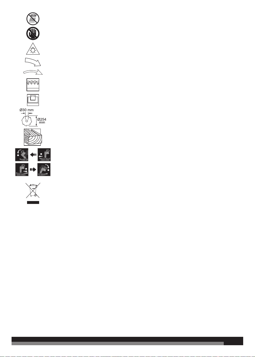
25
25
Do not expose to rain or use in damp
locations.
Keep hands away from the cutting area
and sharp blade.
CAUTION! Do not stare at the operating
lamp.
Blade rotation direction
48 HW
Blade teeth
2.2 mm
Width of cut
Arbor hole and blade size
For cutting wood only
2
1
1
2
Adjust the position of sliding fence
before performing bevel or compound
cuts.
Do not dispose of electric tools together
with household waste material. Electric
tools and electronic equipment that
have reached the end of their life must
be collected separately and returned to
an environmentally compatible recycling
facility.

26
26

27
27

www.aeg-pt.com
Techtronic Industries GmbH
Max-Eyth-Straße 10
D-71364 Winnenden
Germany