USER MANUAL
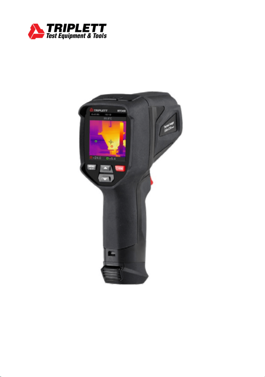
IRTC450
Thermal Imaging Camera


Thermal Imaging Camera
3
Content Page
Welcome
1.
Introduction. ............................................................................ 5
2.
Safety Information. .................................................................. 5
3.
Specifications. ......................................................................... 6
4.
Description .............................................................................. 8
5.
Before You Start ...................................................................... 9
5-1. How to Charge the Battery ............................................ 9
5-2. Power On ..................................................................... 9
5-3. Power Off ..................................................................... 10
5-4. Display Elements. ......................................................... 10
5-5. Shutter ......................................................................... 10
5-6. Temperature Measurement .......................................... 11
5-7. Emissivity Adjustment. ................................................. 11
5-8. Reflected Temperature ................................................. 12
5-9. InfraRead Software ....................................................... 12
6.
Menus. ................................................................................... 13
6-1. Setting Menu. ............................................................... 13
6-2. Image Mode. ................................................................ 14
6-3. Image Palette. .............................................................. 15
6-4. Image Super Resolution. ............................................... 16
6-5. Histogram Mode and Auto Mode. .................................. 16
6-6. Image Alignment. ......................................................... 17
6-7. Image Adjustment ........................................................ 17
6-8. Device Setting. ............................................................. 18
6-9. Time/Date. ................................................................... 18
6-10. USB Mode. ................................................................. 18
6-11. Language. .................................................................. 19
6-12. Auto Power Off. .......................................................... 20
6-13. About. ........................................................................ 20
6-14. Measure Setting. ........................................................ 20
6-14-1. Max Temp ............................................................... 21
6-14-2. Min Temp ............................................................... 21
6-14-3. Emissivity ............................................................... 21
6-14-4. Reflective Temperature ........................................... 21
6-14-5. Alarm Mode ............................................................ 22
6-14-6. Temperature Range ................................................ 22
6-14-7. Temperature Unit .................................................... 23
6-14-8. Reset ...................................................................... 23
6-14-9. Format Memory ...................................................... 23
6-14-10. Factory Settings .................................................... 24

4
Thermal Imaging Camera
Content Page
6-15. Image and Video Menus ............................................. 24
6-15-1. Save Image ............................................................. 24
6-15-2. Video Menu ............................................................. 25
6-15-3. File Browser ............................................................ 25
6-15-4. Play a Video ............................................................ 25
6-15-5. Delete a File ............................................................ 26
7.
Fault Diagnosis and Exclusion. ............................................... 26
8.
PC Software. .......................................................................... 30
8-1. System Requirements. ................................................. 30
8-2. InfraRead Install. .......................................................... 30
8-3. Running. ....................................................................... 31
8-4. Uninstall. ...................................................................... 31
9.
Warranty Statement ............................................................... 32

Thermal Imaging Camera
5
Welcome, and congratulations on your purchase of the Triplett IRTC450 Thermal Imaging Camera
designed
to deliver fast, accurate, and reliable thermal images for a wide range of applications. Whether you
are
inspecting electrical systems, diagnosing HVAC issues, conducting building inspections or preventive
maintenance, the IRTC450 is built to help you work smarter, faster, and safer.
1.
Introduction
•
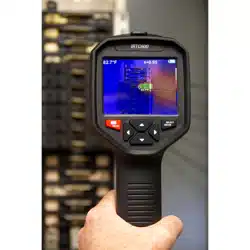
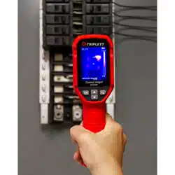
This handheld thermal imaging camera is used for electrical inspections, mechanical diagnostics, and
building inspections, and more.
•
Focus the lens on the object and
the thermal and visual images are displayed on the LCD and can be saved
to the microSD card.
•
Transferring images to a PC is accomplished by removing the microSD card and connecting it to a PC
.
•
In addition to the features mentioned above, the thermal imaging camera provides video recording and
play back.
2.
Safety Information
•
Do not disassemble or modify the thermal imaging camera as this would void the warranty.
•
Do not point the thermal imaging camera at intensive energy sources, for example devices that emit laser
radiation or the sun as this can have unwanted effects on the accuracy of the camera, it can also cause
damage to the detector.
•
Do not use the thermal imaging camera in temperatures higher than 50°C (122°F) or lower than
-20°C (-4°F). Operating in too high or too low temperatures can cause damage to your thermal imaging
camera.
•
Only use the correct equipment to charge the battery. If you do not use the correct battery charger, you
can decrease the performance or the life cycle of your battery. It can also cause the battery to heat up or
cause an explosion resulting in personal injury.
•
Do not disassemble or modify the battery, the battery contains safety and protection devices which, if
they become damaged, can cause the battery to overheat, or cause an ignition or explosion.
•
If there is a leak from the battery and fluid gets into your eyes, do not rub your eyes, flush well with
water and immediately seek medical attention.
•
Do not drill holes in the battery, hit the battery with a hammer, step on it, or subject it to strong impacts
or shocks.
•
Do not put the battery in or near fire, into direct sunlight, or other high-temperature locations.
•
Always charge the battery in the temperature range of 0 to 50°C (32 to 122°F). If you charge the battery
outside of this temperature range, it can cause the battery to become hot or to malfunction and it can
also decrease the performance or life cycle of the battery.
•
Do not permit the battery to get wet.
•
Clean the case with a damp cloth and a mild soap solution. Do not use abrasives, isopropyl alcohol, or
solvents to clean the case, lens, or screen.
•
Be careful when you clean the infrared lens. Do not clean the lens too vigorously as this can damage the
anti-reflective coating.

6
Thermal Imaging Camera
•
Do not expose the thermal imaging camera to sudden temperature changes (e.g., from cold to hot), as
this can lead to internal condensation. To protect your camera, you should power it off and wait long
enough until the camera has become warm enough for the condensation to evaporate.
•
If
you do not use the thermal imaging camera, store it in a cool and dry environment. Remove the battery
from the camera and store it separately to prevent unintended battery discharge
.
3.
Specifications
Imaging and Optical Data
Field
of
View
(FOV)/Minimum
Focus
Distance
62°x 48°/0.5m
Spatial Resolution (IFOV)
3.75mrad
Thermal Sensitivity/NETD
<0.05°C at 30°C (86°F)/50mK
Image Frequency
9Hz
Focus Mode
Focus free
Zoom
1-16x continuous, digital zoom
Focal Length
2.6mm
Focal Plane Array (FPA)/Spectral Response
Uncooled microbolometer/8-14µm
IR Resolution
256 x 192 pixels (49,152 pixels)
Image Presentation
Display
2.4 in. LCD, 320 x 240 pixels
Image Modes
IR image, Visual image, Auto fusion
Color Palettes
Iron, Rainbow, White hot, Black hot, Brown hot, Blue red, Hot
cold, Feather
Measurement
Object Temperature Range
-20 to 550°C (-4 to 1022°F)
Accuracy
±2°C (3.6°F) or ±2% of reading (Environmental temperature 10
to 35°C, object temperature > 0°C)
Measurement Analysis
Spot
Center Spot
Automatic Hot/Cold detection
Auto hot or cold markers
Measurement Corrections
Emissivity (adjustable 0.01-1.0)
Storage of Videos
Storage Media
8GB microSD card and 3.4GB internal EMMC
Video Storage Format
Standard MPG, 320 x 240 at 30fps, on microSD card
>30minutes
Video Storage Mode
IR/visual images; simultaneous storage of IR and visual images

Thermal Imaging Camera
7
Storage of Images
Image Storage Format
Standard JPEG or HIR files including measurement data, on
the microSD card >6000 pictures
Image Storage Mode
IR/visual images; simultaneous storage of IR and visual
images
Image Analysis
Internal image analysis tools, Complete function
Set-Up
Set-Up Commands
Local adaptation of units, language, date and time formats,
information of camera
Languages
12 language options
Digital Camera
Built-in Digital Camera
2 Megapixels
Built-in Digital Lens Data
FOV 65°
Data Communication Interfaces
Interfaces
USB-Type C
USB
Data transfer between camera and PC
Live video between camera and PC
Power System
Battery
Li-ion battery, 4 hours operating time
Input Voltage
DC 5V
Charging System
In camera (AC adapter)
Power Management
Auto Power Off with options 5, 10, 15, 30 min or OFF
Environmental Data
Operating
Temperature
Range
-15 to 50°C (5 to 122°F)
Storage Temperature Range
-40 to 70°C (-40 to 158°F)
Humidity (Operating and Storage)
10% to 90%
Drop Test
2m
Bump
25g (IEC60068-2-29)
Vibration
2g (IEC60068-2-6)
Physical Data
Camera
Weight,
Incl.
Battery
1.1lbs (500g
Camera
Size
(L x W x H)
9.2 x 3 x 4” (235 x 76 x 100mm)
8
Thermal Imaging Camera
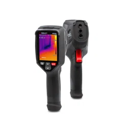
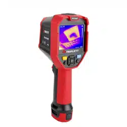
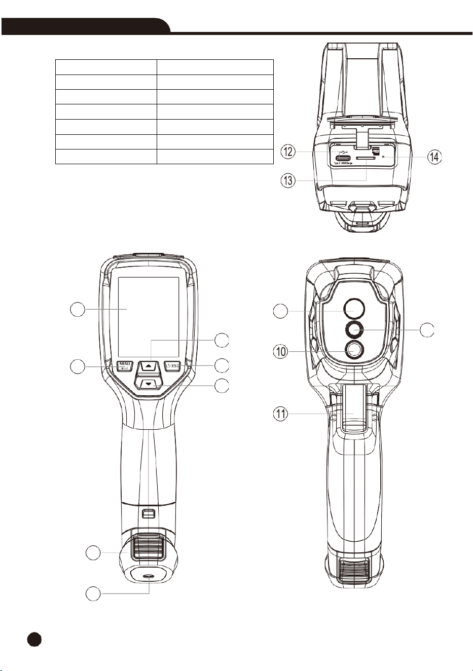
4.
Description
1. LCD Display and Screen
8. Infrared Camera Lens
2. MENU Button
9. Laser Ranging Lens
3. Up Arrow Button
10. Flashlight
4. Power/ESC Button
11. The Trigger
5. Down Arrow Button
12. USB-C Interface
6. Battery
13. microSD Card Slot
7. Hole for Tripod Insertion
14. Battery Charging LED Indicator
1
2
3
4
5
6
7
8
9
Thermal Imaging Camera
9
5.
Before You Start
5-1. How
to
Charge
the
Battery
•
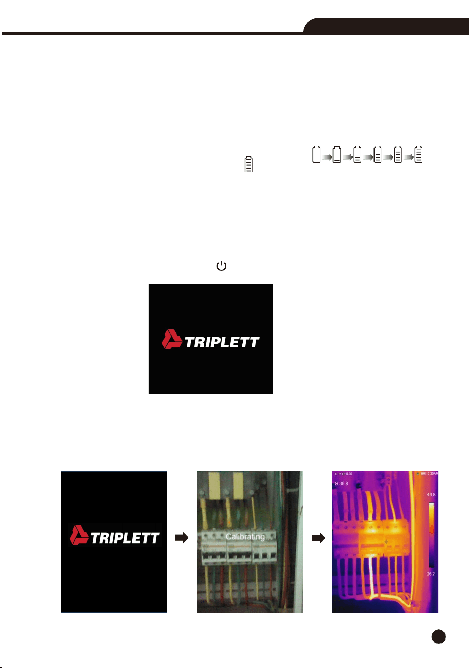
Before
you use the thermal imaging camera for the first time, charge the battery for about three and a
half hours. The battery
status is shown on the six-segment charge indicator.
•
Charge
the
battery as follows:
1.
Connect the cable to USB-C input on the camera and USB-A end to a power adaptor. The charging
indicator will be visible on the display while the battery charges.
2.
Charge until the charge indicator changes to “
“.
3.
Disconnect from ac power when the battery is fully charged.
Note:
Make sure that the camera is near room temperature before you connect it to the charger. Do
not
charge in unusually hot or cold areas. When you charge in extreme temperatures, battery
capacity may be decreased
.
5-2. Power
On
To
turn
the
camera
on,
push
the
Power
“
/ESC
”
button.
Note:
After you power on your thermal imaging camera, it needs sufficient warm-up time for the most
accurate temperature measurements and best image quality. The visible image will appear first, and the
thermal sensor will calibrate internally for several seconds. After that the thermal image will also be
displayed on the screen.
10
Thermal Imaging Camera
5-3. Powering Off
When
the thermal imaging camera is turned on, push and hold
the
Power
“ /ESC
”
button for two
seconds and it will turn off.
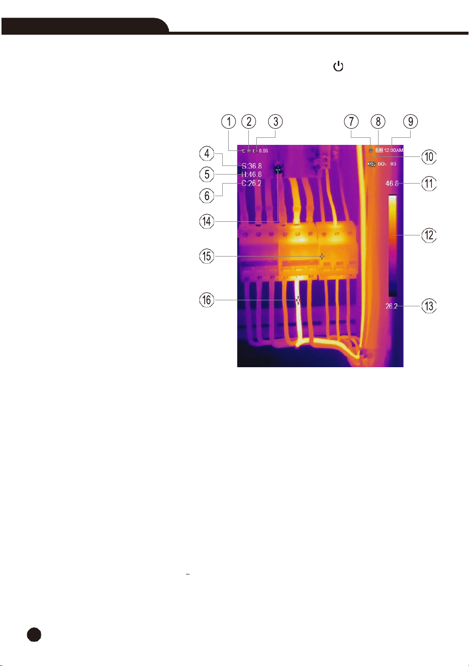
5-4. Display Elements
1-
Temperature units
2-
Distance units
3-
Emissivity
4-
Center spot temperature reading
5-
Hot temperature reading
6-
Cold temperature reading
7-
SD card
8-
Battery capacity status
9-
Time
10-
Video recording indicator
11-
MAX temperature of current scene
12-
Color bar
13-
MIN temperature of current scene
14-
MIN temperature cross point
15-
Center cross point
16-
MAX temperature cross point
5-5. Shutter
•
The thermal image becomes blurry when the thermal imaging camera is not properly correcting
after some minutes or if you change to a different target. An automatic correction will take place to
improve the image quality.
5-6. Temperature
Measurement
•
All objects radiate infrared energy, the quantity of energy radiated is based on the actual
surface temperature and the surface emissivity of the object. The thermal imaging camera
senses the infrared energy from the surface of the object and uses this data to calculate an
estimated temperature value.
•
Many common objects and materials such as painted metal, wood, water, skin and cloth are
very good at radiating energy, and it is easy to get relatively accurate measurements, for
surfaces that are good at radiating energy (high emissivity), the emissivity factor is >0.90.
•
This simplification does not work on shiny surfaces or unpainted metals as they have an
emissivity of <0.6, these materials are not good at radiating energy and are classified as low
emissivity.

Thermal Imaging Camera
11
•
To more accurately measure materials with low emissivity, an emissivity correction is
necessary, adjustment to the emissivity setting will usually allow the thermal imaging camera
to calculate a more accurate estimate of the actual temperature.
•
For more information, please see Emissivity Adjustment to get the most accurate temperature
measurements.
5-7. Emissivity Adjustment
•
Emissivity of a
surface can significantly influence the apparent temperatures that the
thermal imaging camera observes.
Using the correct emissivity value is important to make the
most accurate temperature measurements.
•
Understanding the emissivity of a surface can help you obtain more accurate temperature
measurements, although this may not always be the case.
Note:
Surfaces with an emissivity of <0.60 make reliable and consistent determination of actual
temperature problematic, the lower the emissivity, the more potential errors are associated with
the thermal imaging camera’s temperature measurement calculations. This is also true even
when adjustments to the emissivity are performed properly.
•
Emissivity is set directly as a value or from a list of the emissivity values for some common
materials, the emissivity displays on the LCD Screen as E=x.xx.
•
The following table gives typical emissivity of important materials.
5-8. Reflected Temperature
•
Using
the offset factor, the reflection is calculated out due to the low emissivity and the
accuracy of the temperature measurement is enhanced.
In most cases, the reflected temperature is the same as the ambient air temperature. Only when
high emission objects with
significantly higher temperatures are near the measured object should
the reflected temperature be determined and applied. For objects with high emissivity, the reflected
temperature has minimal impact.
•
The reflected temperature can be set individually. Follow these steps to get the right value for
the reflected temperature.
1. Set the emissivity to 1.0.
2. Adjust the optical lens to near focus.
Material
Emissivity
Water
0.96
Stainless
steel
0.14
Aluminum
plate
0.09
Asphalt
0.96
Concrete
0.97
Cast
iron
0.81
Rubber
0.95
Wood
0.85
Brick
0.75
Material
Emissivity
Tape
0.96
Brass
plate
0.06
Human
skin
0.98
PVC
plastic
0.93
Polycarbonate
0.80
Oxidized
copper
0.78
Rust
0.80
Paint
0.90
Soil
0.93
12
Thermal Imaging Camera
3.
Looking in the opposite direction away from the object, take a measurement and freeze the
image.
4. Determine the average value of the image and use that value for your input of the reflected
temperature.
5-9. InfraRead Software
•
The thermal
imaging camera is supplied with free InfraRead software. This Software contains
features to analyze images, organize data and information, and make professional reports.
•
You can customize the reports and add your company logo and information.
•
You can save the reports as .pdf or .xlsx and export it.
6.
Menus
The
menus allow you to access images, measurements, emissivity, color palettes, temperature
measurement
range, review images and video, and access settings.
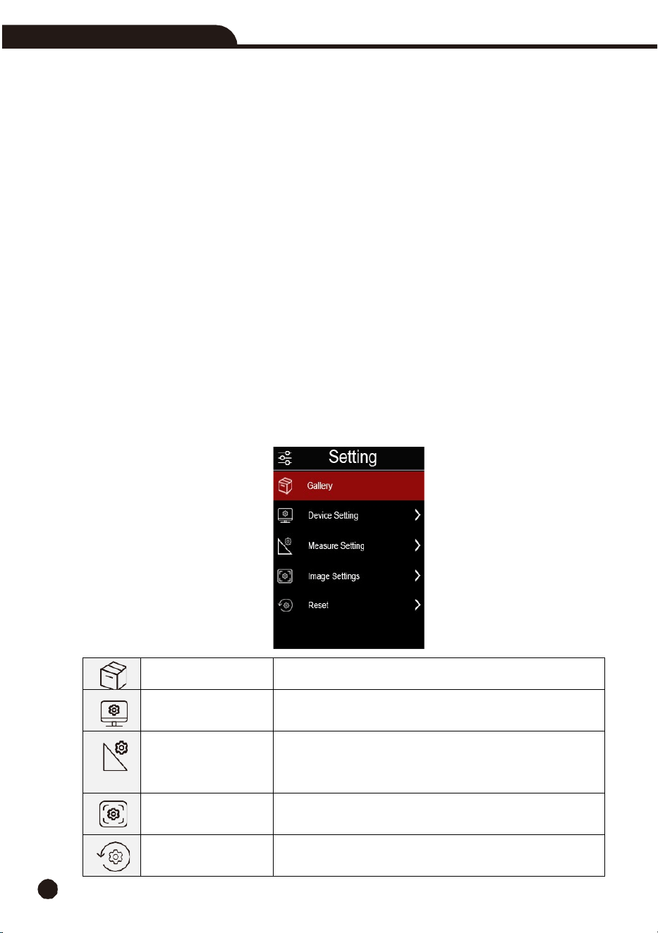
6-1. Setting Menu
•
Press the
Menu
button, the
Setting
menu will pop up. The
Setting
menu is the main interface of the
thermal imaging camera’s menus.
•
It contains the
Gallery
,
Device Setting
,
Measure Setting
,
Image Setting
, and
Reset
.
Gallery
Enter gallery.
Device Setting
System Settings, including time and date, language, flashlight,
and automatic shutdown
Measure
Setting
Contains settings for maximum temperature, minimum
temperature, reflection temperature, emissivity, alarm mode,
range, and temperature units
Image Setting
Contains settings such as color palette, super-resolution, image
translation.
Reset
Includes
restoring
factory
settings
and
formatting
storage
settings.
Thermal Imaging Camera
13
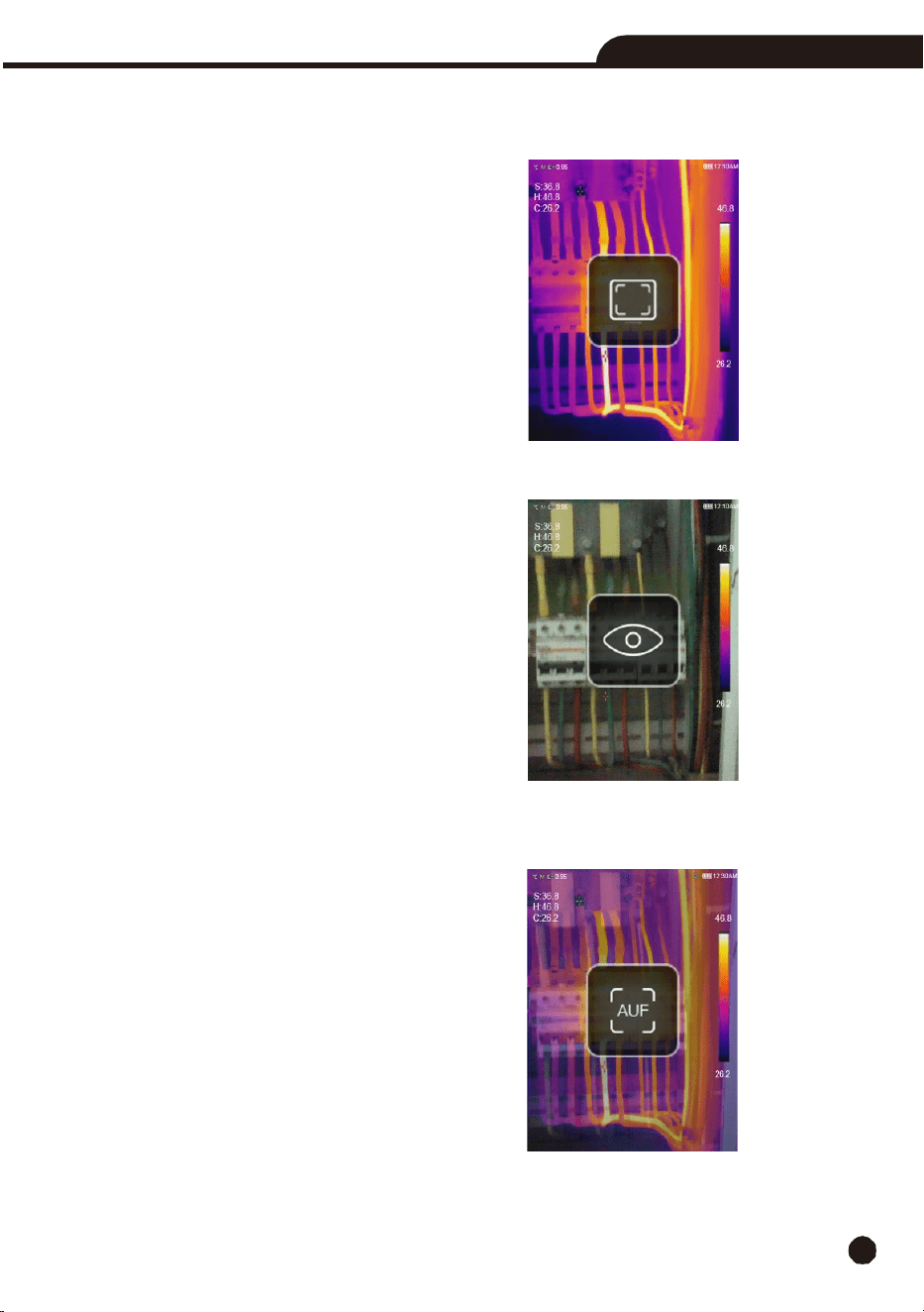
6-2. Image
Mode
•
In
the main
menu,
press
the
Up
or
Down
Button to switch between image modes.
•
We
offer
three
image
modes
to
choose
from:
IR:
Displays
only
infrared
image.
Visible:
Displays
only
visible image
AUF:
Auto Fusion mode, compare the center area temperature with full screen, the thermal imaging
camera will calculate the mix ratio of infrared and visual images automatically.
14
Thermal Imaging Camera
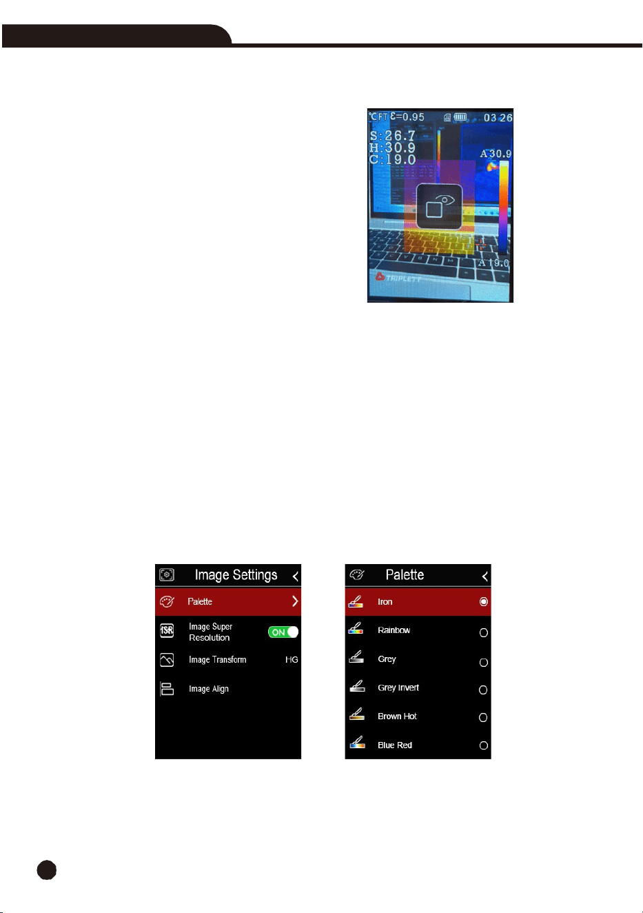
Picture-in-Picture:
The thermal image is overlayed in the center of the screen on top of a normal
visible light image.
6-3. Image
Palette
•
A
variety of palettes are available for specific applications, the standard palettes offer an equal, linear
presentation of colors that allow for best presentation of detail.
Standard Palette
1.
In the main menu, press the
Up
or
Down
Button,
highlight
“
Palette
”.
2.
Press the
MENU
Button and the Image submenu will pop up which contains 8 color palettes.
3.
Press the
Up
or
Down
Button, highlight the palette you want, and press enter.
4.
The palette will change according to your selection.
Thermal Imaging Camera
15
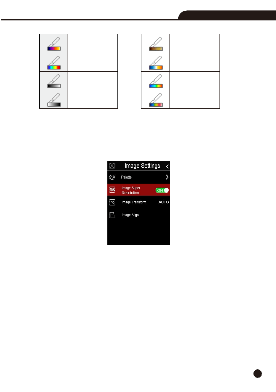
6-4. Image
Super
Resolution
•
Image
super-
resolution technology is a technique that upgrades low resolution images captured by
the thermal imaging camera to higher resolution through embedded algorithms.
•
It can make the image clearer and compensate for the shortcomings brought on by low resolution.
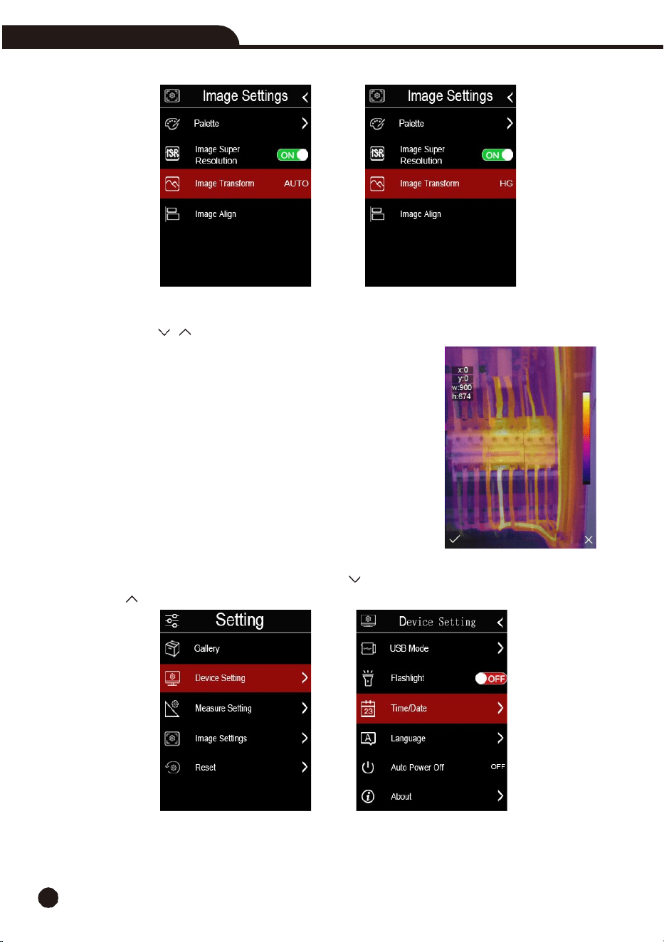
6-5. Histogram Mode and Auto
Mode
•
Auto
Mode:
Level and span are decided by
the thermal image of minimum and maximum temperature,
the relationship between temperature and color is linear.
•
Histogram Mode:
The thermal image is enhanced by histogram algorithms, the relationship between
temperature and color is not linear, some part of the image is enhanced.
•
Press the
Power/Lock
Button to change the mode.
Iron
Brown hot
Rainbow
Blue red
White hot
Hot cold
Black hot
Feather
16
Thermal Imaging Camera
6-6. Image
Alignment
•
Press
the
“
, ”
buttons
to
align
the
visible and
infrared images.
•
Press
the
Power/Lock
button
to
cancel
the
setting,
press
the
Menu/OK
button
to
save
the
alignment
setting.
6-7. Image
Adjustment
There are two modes for image adjustment: Histogram Auto.
6-8. Device
Setting
There are multiple pages in Device setting, use the Down button to go to next setting, or
use the Up button to go to previous setting.
Thermal Imaging Camera
17
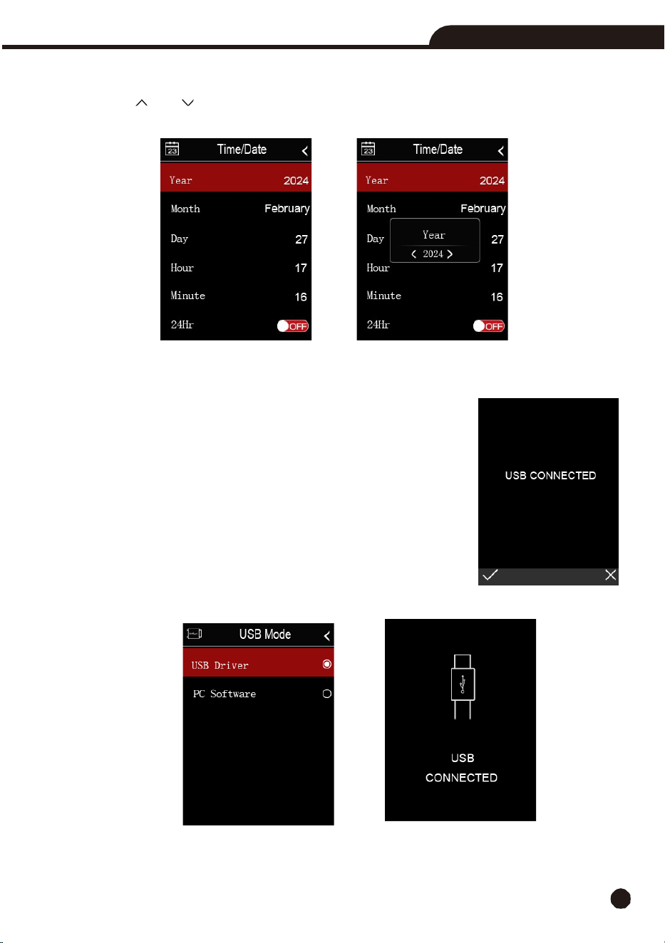
6-9. Time/Date
Press the
Up
or
Down
button to select year, month, and day, then press the
MENU/OK
or the
Right
button to change the Time/Date.
6-10. USB
Mode
•
Connect the USB cable to the thermal imaging camera, the following message will pop up:
•
There are two modes for USB: USB Driver or PC Software, press the
Up
or
Down
button to switch mode.
•
USB
Driver:
Browse files stored on the SD card on your computer, if you
select Storage mode, the following picture will be displayed
:
18
Thermal Imaging Camera
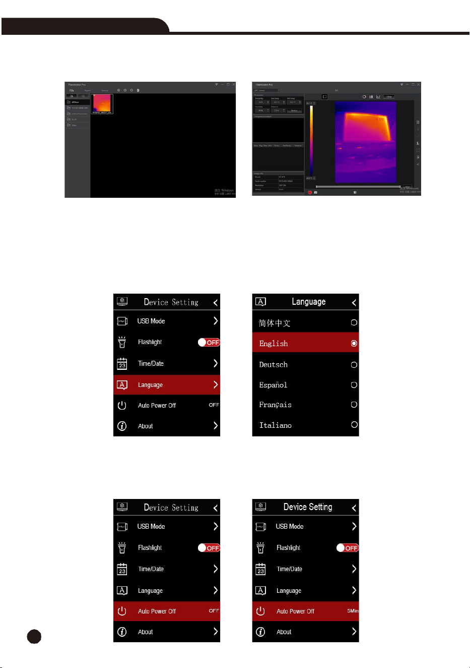
•
PC
Software:
The
device
is
a
USB
camera
for
your
computer,
if you select
this
mode,
open
“
InfraRead
”
and select “
Camera
” menu to display
the following pictures:
•
In
the PC software, you can analyze the thermal image in real time, or you can record and analyze
the thermal video in real time.
6-11. Language
Press
the
Up
or
Down
Button to select the desired language and use
MENU/OK
button to set the
selected language.
6-12. Auto
Power
Off
•
There
are
five
options
in the Auto Power Off menu: “OFF”, “5Min”, “10Min”, “15Min” and “30Min”.
•
When
you press
the
MENU/OK
button,
the
timer
of
Auto
Power
Off
will
be
cleared
and
re-timed.
Thermal Imaging Camera
19
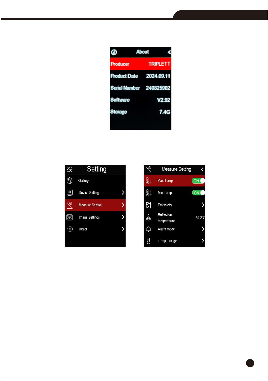
6-13. About
The
info
menu
contains
all
camera information
: Producer, Product Date, Serial Number, Software Version
,
and storage.
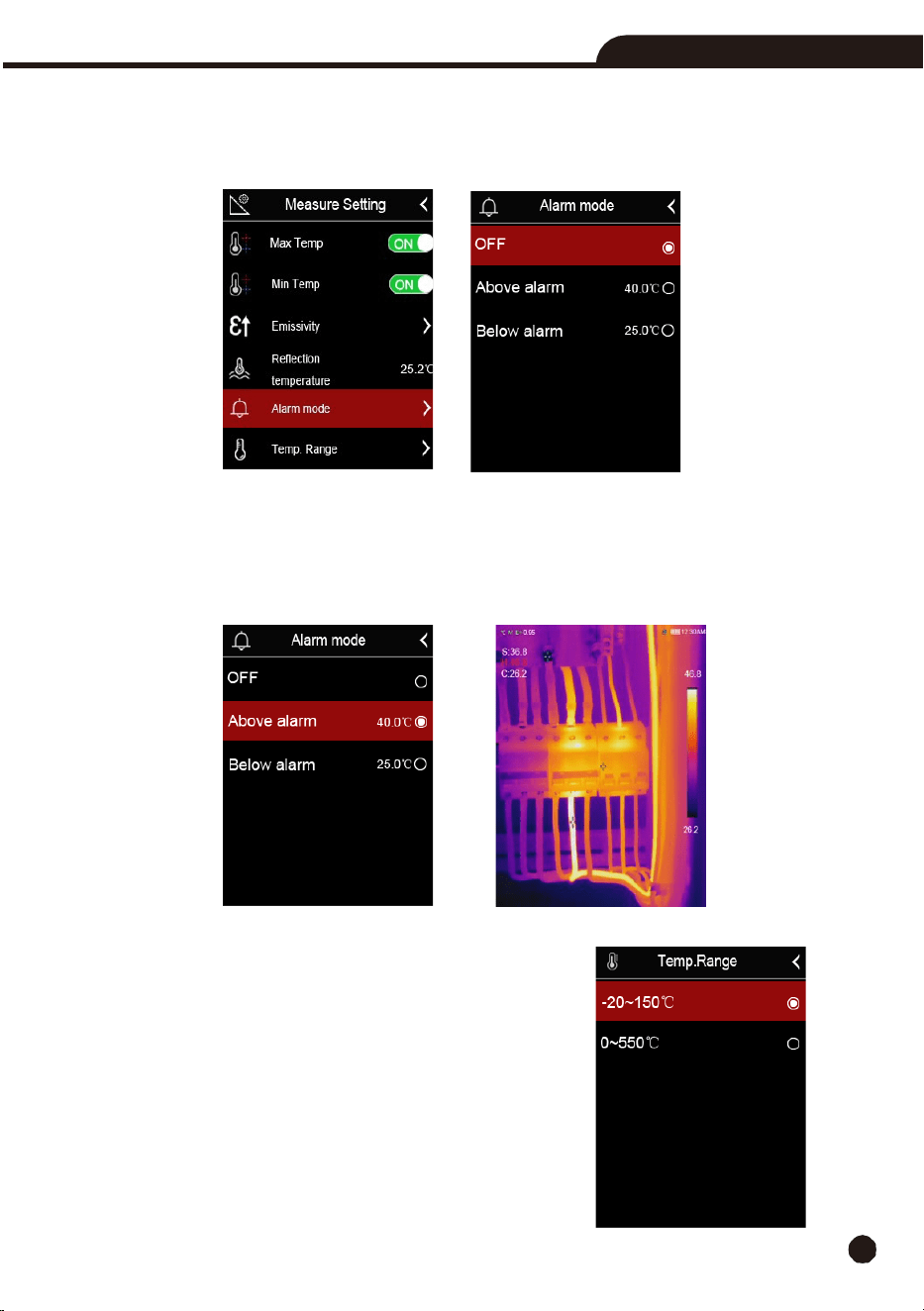
6-14. Measure
Setting
•
Select the “
Measure Setting
” menu, the Measure Setting menu will be displayed.
•
The
options
in
Measure
setting
menu are shown below.
6-14-1. Max
Temp
Press
the
MENU/OK
Button
to
turn
maximum temperature measurement on or off.
6-14-2. Min
Temp
Press
the
MENU/OK
Button to turn the minimum temperature measurement on or off.
20
Thermal Imaging Camera
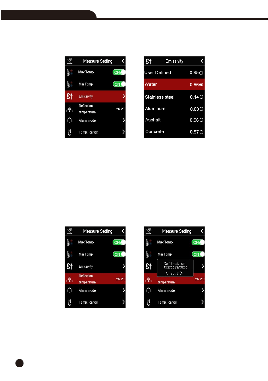
6-14-3. Emissivity
•
In
emissivity
submenu,
press
the
“
Up
”
and
“
Down
”
arrow
to
change
the
emissivity
values.
•
“Emiss”
sets
object
emissivity,
the
value
range
is
0.01
to
1.00.
6-14-4. Reflective
Temperature
•
In
reflective
temperature
submenu,
press
the
“
Up
”
and
“
Down
”
arrow
to
change
the
temperature
values.
•
Reflective temperature is important for radiometric temperature measurements. This thermal imaging
camera has temperature compensation for reflective temperatures. To obtain a more accurate
temperature measurement, ensure the reflective temperature is set correctly.
•
In most cases, the reflected temperature is identical to the ambient temperature, only when objects
with strong emissions with much higher temperature are in the proximity of the object being
measured, the reflected temperature must be set.
Thermal Imaging Camera
21
6-14-5. Alarm Mode
•
OFF:
Turn
off
the
alarm
display
and
sound.
•
Below
Alarm:
If
the temperature of the object below the low alarm value, there will be alarm
sound and display.
•
Above
Alarm:
If the temperature of the object exceeds the above alarm value, there will be
alarm sound and display.
6-14-6. Temperature
Range
•
You can select from two temperature ranges: “-20
to
150°C”
and
“0
to
550°C”
•
If you are not sure, select
“-20
to
150°C”.
6-14-7. Temperature Unit
•
Temperature
Unit: Choose from three types: °C, °F and K.
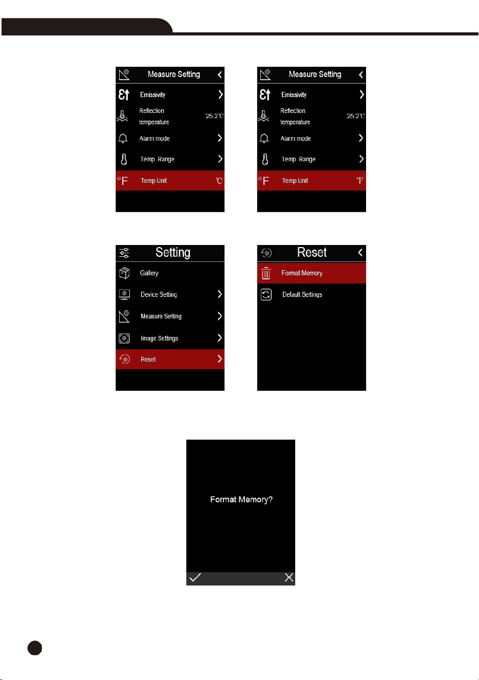
22
Thermal Imaging Camera
•
Conversion relationship: °F=1.8x°C+32, K=273.15+°C.
6-14-8. Reset
6-14-9. Format
Memory
Format
Memory
operation
will
format
the complete Picture
Gallery,
the
device
setting
is
not
affected.
Thermal Imaging Camera
23
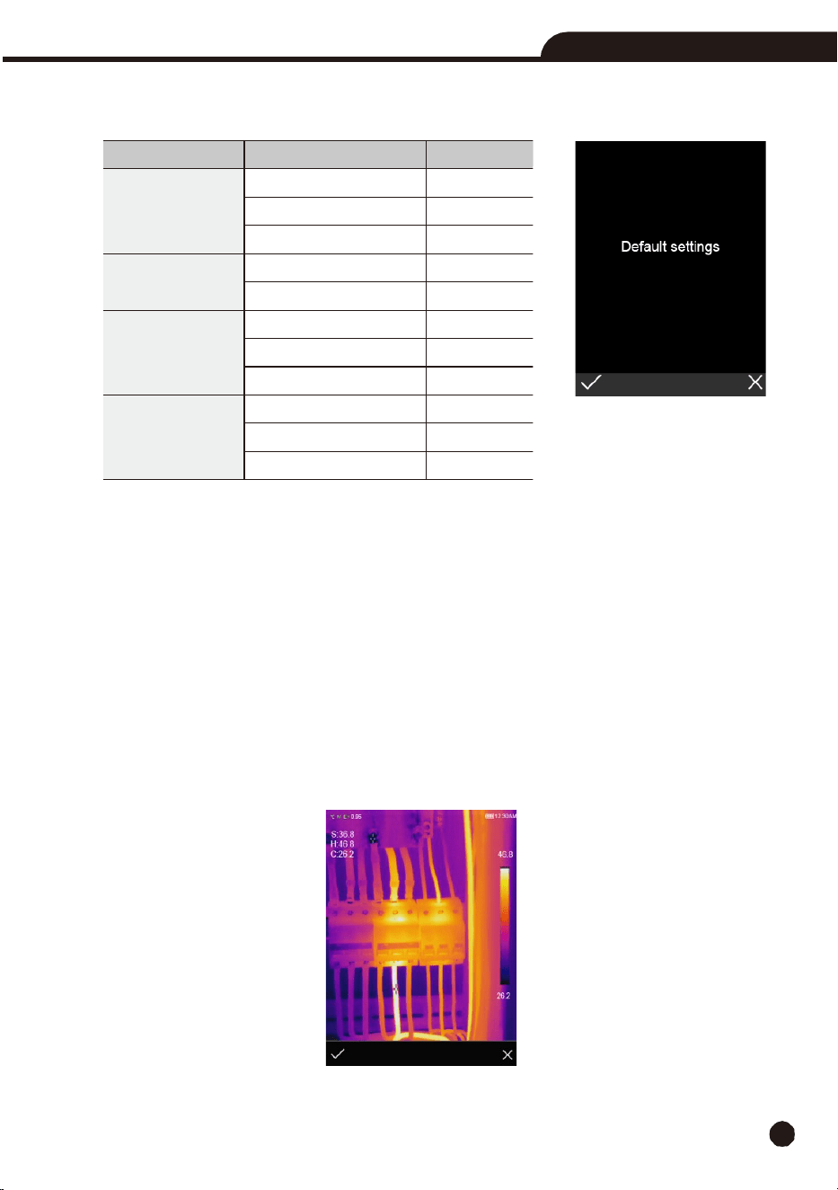
6-14-10. Factory
Settings
The Factory
Settings
of
the
t
hermal
imaging camera are
as
follows:
6-15. Image and Video
Menus
•
The thermal imaging camera
has
photo
and
video
functions.
•
In
photo function, the thermal imaging camera can save thousands of images. Image resolution is
1280 x 960. The image format is “.jpg”
and infrared and visible data are stored in one image.
•
In
video
function,
the thermal imaging
camera
has
“.mp4”
video
capability
and
saves
data
in
.mp4
format.
Note:
Images and video files are stored on the microSD card. Images can easily be read and analyzed within
the InfraRead app and InfraRead software.
6-15-1. Save
Images
1.
In
desktop,
press
the
Trigger
button,
freeze
an
image,
the
save
menu
will
display.
2.
Press the
MENU
Button to save the image. It will flash for a second, after the image is saved, the
display will return to live image mode.
Item
Parameter
Value
Measurement
Center Spot Measurement
On
Hot Spot Measurement
Off
Cold Spot Measurement
Off
Measurement
Parameters
Emissivity
0.95
Reflective Temperature
25°C
Image
Mode
Infrared
Palette
Iron
Adjustment
Auto
System Setting
Language
English
USB mode
USB Driver
Lamp
Off
24
Thermal Imaging Camera
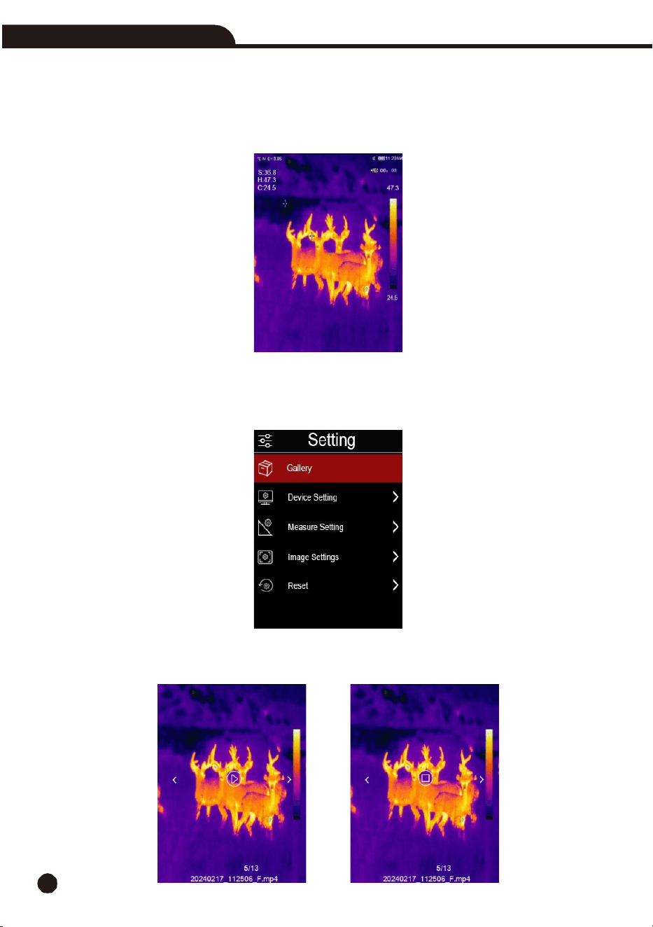
6-15-2. Video
Menu
The
thermal
imaging camera
features “.mp4”
video
capture.
1.
In
desktop,
press
the
Trigger
button
and
hold
for
about
2
seconds to start
video
capture.
2.
To
stop
video
capture,
press
the
Trigger
button
again,
the
video
is saved
on the microSD card.
6-15-3. File Browser
Press
the
MENU
Button,
highlight
“
Gallery
”, then press the
MENU
Button and the file browser will
pop up, which displays
pictures and videos saved on the microSD Card.
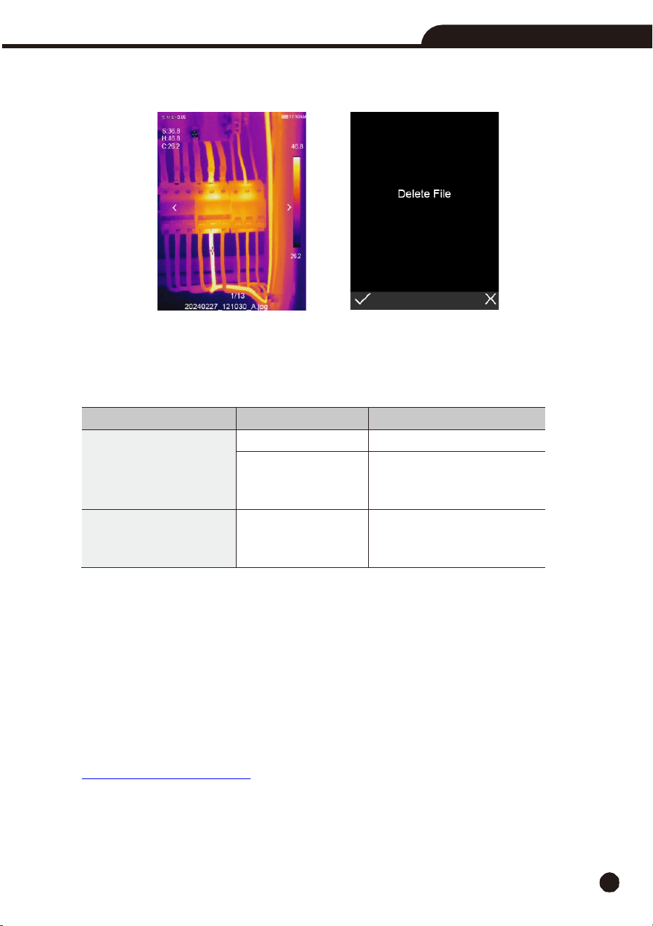
6-15-4. Play a Video
When the selected file type is video, press the Trigger button to play video or stop to play the video.
Thermal Imaging Camera
25
6-15-5. Delete a File
Press
the
MENU
Button,
then
press
the
MENU
Button
again
to
delete
the
current
file.
7.
Fault Diagnosis and Exclusion
•
If
you
encounter
any
problems
while
using
the
thermal imaging camera,
overhaul
according
to
the
following
table.
Encountered Issue
Cause
of
the Issue
Solution
Thermal imaging camera
cannot start
No battery
Insert
the
battery
No power
Charge the battery and if that
doesn’t help, replace
the
battery
Thermal
imaging camera
is
shutting
down
No power
Charge the battery and if that
doesn’t help, replace
the
battery
8.
PC
Software – InfraRead
8-1. System
Requirements
•
Windows X or higher with .NET Framework 4.5 installed.
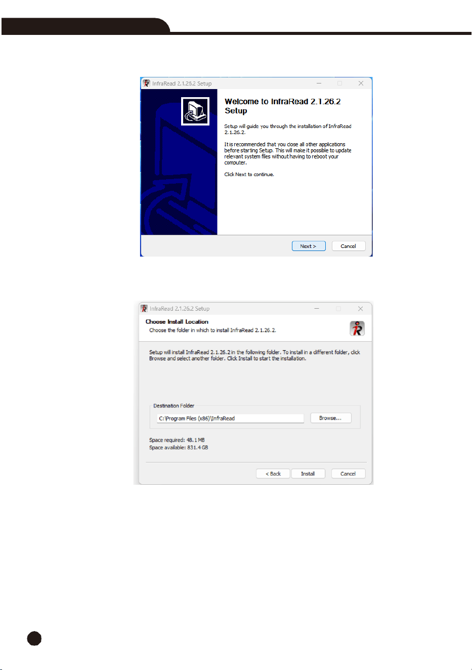
8-2. InfraRead Install
**NOTE:
Please download the latest InfraRead Software from
www.triplett.com/software
26
Thermal Imaging Camera
1.
Click to run “setup.exe” and follow the prompts to install
.
2.
Click “Next” to install, until the installation is finished.
Thermal Imaging Camera
27
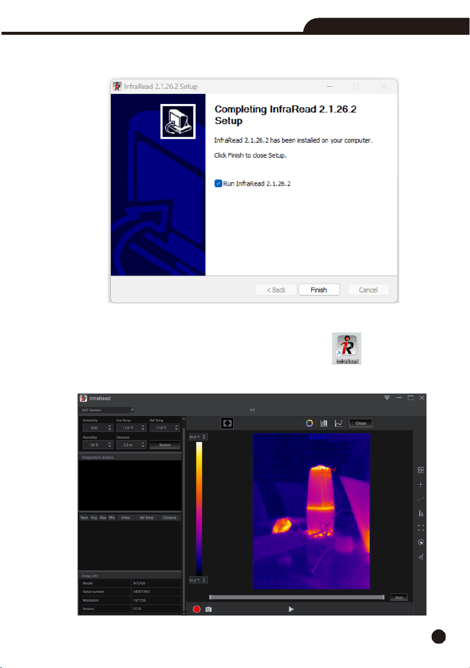
3.
The Installation was Successful after you click “Finish” as seen below.
8-3. Running
After
ensuring
the
InfraRead software
has
been
installed,
click
shortcuts
o
n
the
desktop
or
start
menu
to
run
the
software.
28
Thermal Imaging Camera
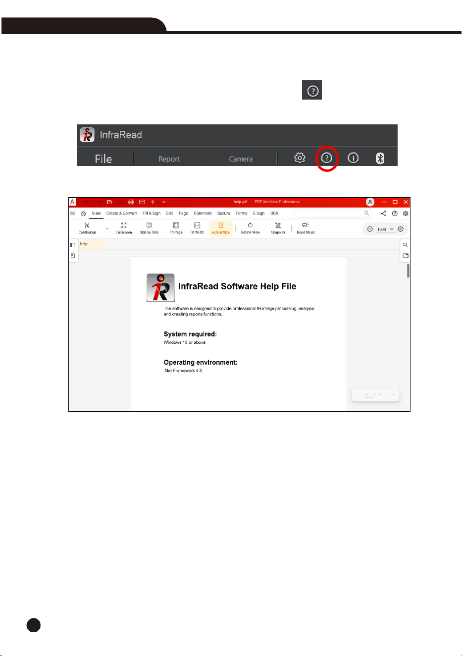
8-4. Software Help File
Locate the Software Help Icon in the menu bar. Click on the icon to Open the Software
Help File.
8-4. Uninstall
Uninstall InfraRead by locating it in the Installed apps menu, click “Uninstall” then click “Yes” to finish
the uninstall.

Thermal Imaging Camera
29
9.
Warranty Statement
Triplett Test Equipment offers a three-year warranty to the original purchaser of its products.
We guarantee that our products will be free from defects in workmanship and materials for
three (3) years from the purchase date.
This warranty does not cover:
§
Products purchased from unauthorized distributors.
§
Items that have been repaired or altered by unauthorized individuals.
§
Damage from misuse, abuse, misapplication, negligence, or accidents.
§
Products with altered, defaced, or removed serial numbers.
§
Accessories, including batteries.
Copyright © 2025
Triplett
www.triplett.com