Operating Instruction for
Thermal Imager
Thermal Imager
IRTC950


3
Thermal Imager
Page
5
5
7
9
10
10
10
11
11
12
13
13
13
13
13
14
15
15
16
16
16
19
20
20
21
22
22
23
23
24
24
24
25
25
25
28
30
Content
1.Introduction.................................................................................
2.Safety Information.......................................................................
3.Specifications..............................................................................
4.Structure Description....................................................................
5.Before You Start............................................................................
5-1.How to Charge the Battery.......................................................
5-2.Power On.................................................................................
5-3.Power Off................................................................................
5-4.Desktop...................................................................................
5-5.Lens........................................................................................
5-6.Focus......................................................................................
5-7.Shutter....................................................................................
5-8.LED Light.................................................................................
5-9.Laser.......................................................................................
5-10.Temperature Measurement......................................................
5-11.Emissivity Adjustment............................................................
5-12.Reflected Temperature...........................................................
5-13.Thermal Imager Reporter Software.........................................
6.Menus..........................................................................................
6-1.Main Menu..............................................................................
6-2.Image Mode............................................................................
6-3.Image Palette..........................................................................
6-4.Image Adjustment...................................................................
6-4-1.Lock Operation...................................................................
6-4-2.Histgram Mode and Auto Mode...........................................
6-5.Measurement Menu.................................................................
6-6.Parameter Menu.....................................................................
6-6-1.Ambient Temperature Composation....................................
6-6-2.Reflective Temperature......................................................
6-6-3.Atmospheric Humidity........................................................
6-6-4.Delta Temperature Compesation.........................................
6-6-5.Distance............................................................................
6-6-6.Emissivity..........................................................................
6-7.Settings Menu.........................................................................
6-7-1.Device Setting...................................................................
6-7-2.Measure Setting................................................................
6-7-3.Reset.................................................................................

4
Thermal Imager
Page
31
33
33
34
34
35
35
35
35
35
35
35
37
38
38
38
39
39
39
Content
6-8.Camera Menu..........................................................................
6-9.Video Menu.............................................................................
6-10.Files Browser.........................................................................
6-11.USB Mode..............................................................................
6-12.HDMI Output..........................................................................
7.Android/iOS APP InfraRead..............................................................
7-1.Software Install and Uninstall..................................................
7-1-1.System Required................................................................
7-1-2. InfraRead App Install......................................................
7-2. InfraRead Function.................................................................
7-2-1.Import Pictures..................................................................
7-2-2.Analyze..............................................................................
7-2-3.Report and Share...............................................................
8.PC Software..................................................................................
8-1.System Required.....................................................................
8-2. InfraRead Pro Install..............................................................
8-3.Running..................................................................................
8-4.Uninstall.................................................................................
9.Fault Diagnosis and Exclusion.......................................................

5
Thermal Imager
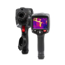
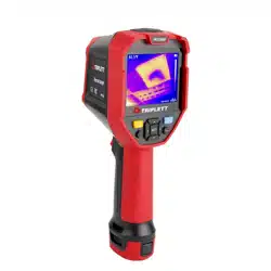
1.Introduction
Overview
• The Thermal Imager is handheld imaging camera used for predictive maintenance, equipment troubleshooting,
and verification.
• Focus the len to the object, Then the thermal and visual images are displayed on the LCD and can be saved to a
Micro SD Memory card.
• Transferring images to a PC is accomplished by removing the SD memory card and connecting it to a PC through
the included card reader, or transfer the images and video stream to the smart device with “Thermoview” apps
installed.
• In addition to the features mentioned above, the Thermal Imager provide video recording with audio and play
back.
2.Safety Information
• To prevent eye damage and personal injury, do not look into the laser. Do not point laser directly at persons or
animals or indirectly off reflective surfaces.
• Do not disassemble or do a modification to the Thermal Imager.
• Do not point the Thermal Imager (with or without the lens cover) at intensive energy sources, for example devices
that emit laser radiation, or the sun.
• This can have an unwanted effect on the accuracy of the camera. It can also cause damage to the detector in the
Thermal Imager.
• Do not use the Thermal Imager in a temperature higher than 50°C (122°F), lower than -20°C (-4°F), High
temperature or low temperature can cause damage to the Thermal Imager.
• Only use the correct equipment to discharge the battery.
• If you do not use the correct equipment, you can decrease the performance or the life cycle of the battery, If you
do not use the correct equipment, an incorrect flow of current to the battery can occur, This can cause the battery
to become hot, or cause an explosion and injury to persons.
• Do not pull out the battery when the thermal imager is working.
• If you pull out the battery when the thermal imager is working, it may cause the thermal imager work unnormal.
• Do not disassemble or do a modification to the battery.
• The battery contains safety and protection devices which, if they become damaged, can cause the battery to
become hot, or cause an explosion or an ignition.
• If there is a leak from the battery and the fluid gets into your eyes, do not rub your eyes, Flush well with water
and immediately get medical care.
• Do not make holes in the battery with objects, Do not hit the battery with a hammer, Do not step on the battery,
or apply strong impacts or shocks to it.
• Do not put the battery in or near a fire, or in direct sunlight, or other high-temperature locations, Do not solder
directly onto the battery.
• Always charge the battery in the special temperature rang.
• The temperature range through which you can charge the battery is 0 to 50°C (32 to 122°F), If you charge the
battery at temperatures out of this range, it can cause the battery to become hot or to break, It can also decrease
the performance or the life cycle of the battery.

6
Thermal Imager
• Do not get water or salt water on the battery, or permit the battery to get wet.
• Clean the case with a damp cloth and a weak soap solution. Do not use abrasives, isopropyl alcohol, or solvents
to clean the case or lens/screen.
• Be careful when you clean the infrared lens, Do not clean the infrared lens too vigorously, This can damage the
anti-reflective coating.
• Take the Thermal Imager from from cold to hot, it will appear condensation in thermal Imager, To protect the
Thermal Imager, you should power of the Thermal Imager, wait until the Thermal Imager has become war enough
for the condensation to evaporate.
• If you do not use the Thermal Imager, put the Thermal Imager in cool and dry environment, if you store Thermal
Imager equipped with the battery, the power of the battery will be exhausted.
a.When the product is charging, the flashlight function cannot be used.
b.Audio Out.

7
Thermal Imager
3.Specifications
Imaging and Optical Data
Field of View (FOV)/Minimum Focus Distance
Spatial Resolution (IFOV)
Thermal Sensitivity/NETD
Image Frequency
Focus Mode
Zoom
Focal Length
Focal Plane Array (FPA)/Spectral Range
IR Resolution
Image Presentation
Display
Image Modes
Color Palettes
Measurement
Object Temperature Range
Temperature Accuracy
Laser Distance Meter
Laser Distance Accuracy
Measurement Analysis
Spot
Automatic Hot/Cold Detection
Line
Area
Measurement Corrections
Storage of Videos
Storage Media
Video Storage Format
Video Storage Mode
Storage of Images
Image Storage Format
Image Storage Mode
Image Analyse
17° x 12.7°/ 0.5m
0.77mrad
<0.04°C at 30°C (86°F)/40mK
25Hz
Manual
1-32x continuous, digital zoom.
22mm
Uncooled microbolometer / 8-14µm
384 x 288 pixels
3.5in. LCD, 640x480 pixels, Touch screen
IR image, Visual image, Picture in picture, Auto fusion, Laser distance
meter with fusion.
IRON, Rainbow, Grey, Grey Inverted, Brown, Blue-red, Hot-cold,
Feather, Above alarm, Below alarm, Zone alarm, Vision zone
-20 to 150°C (-4 to 302°F) / 0 to 650°C (32 to 1202°F)
±2°C (±3.6°F) or ±2% of reading (Environment temperature 10 to
35°C, Object temperature >0°C).
0.05 to 30m (0.15 to 98ft)
Typically ±5mm (0.2in)
Center Spot, Three manual spots
Auto hot or cold markers
Two lines analyse
Three areas analyse
Emissivity, Reflected temperature, Ambient temperature,
Atmospheric humidity, Infrared compensation, Distance compensation
8Gbytes Micro SD card or 3.4GB internal EMMC
Standard MPEG-4 encode, 640x480 at 30fps, on memory card >60
minutes
IR/visual images; simultaneous storage of IR and visual images
Standard JPEG,or HIR files including measurement data, on memory
card >6000 pictures
IR/visual images; simultaneous storage of IR and visual images
Internal image analyse tools, Complete function.

8
Thermal Imager
Set-Up
Laser
Set-up commands
Languages
Digital Camera
Built-in Digital Camera
Built-in Digital Lens Data
Data Communication Interfaces
Interfaces
USB
Video Out
Wifi
Power System
Battery
Input Voltage
Charging System
Power Management
Environmental Data
Operating Temperature Range
Storage Temperature Range
Humidity (Operating and Storage)
Drop Test
Bump
Vibration
Physical Data
Camera Weight, Incl. Battery
Camera Size (LxWxH)
<Class2
Local adaptation of units, language, date and time formats, information
of camera
Multinational
5 Megapixels
FOV 59°
USB-Mini, HDMI
Data transform between camera and PC; Live video between camera
and PC
HDMI
802.11, transfer images and realtime video stream
Li-ion battery, 4 hours operating time
DC 5V
In camera (AC adapter)
Automatic shutdown
-15 to 50°C (5 to 122°F)
-40 to 70°C (-40 to 158°F)
10% to 90%
2m
25g(IEC60068-2-29)
2g(IEC60068-2-6)
<846g
260 x 101 x 120mm
9
Thermal Imager
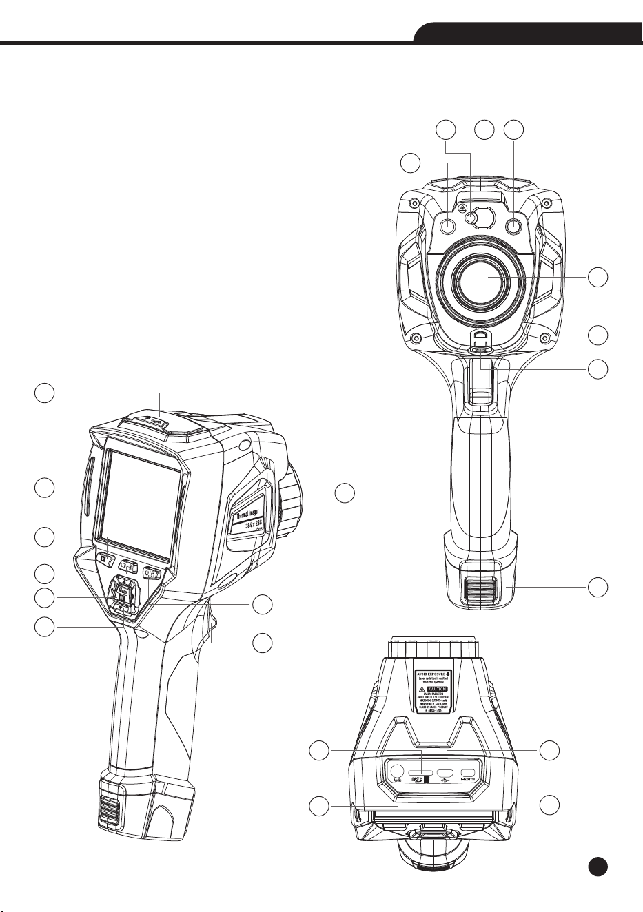
4.Structure Description
1-LED Light
2-Laser Pointer
3-Laser Distance Meter Len
4-Visual Camera
5-Infrared Camera Lens
6-Dust Cover Lanyard Hole
7-Hole for Tripod Insertion
8-Battery
9-Interface and Cover
9.1-Audio/Microphone
9.2-Micro SD Card Slot
9.3-Micro USB/Charge
9.4-HDMI
1
2 3 4
5
6
7
8
9
10
11
12
13
14
15
16
17
10-LCD Display and Touch Screen
11-Focus Ring
12-Images Browse Button
13-Laser Distance Measure Button
14-Power/Lock Button
15-Menu/Select Button
16-Up/Down/Right/Left Button
17-Trigger
9.2 9.3
9.4
9.1
10
Thermal Imager
5.Before You Start
5-1.How to Charge the Battery
• Before you use the Thermal Imager for the first time, charge the battery for three and three-half hours.
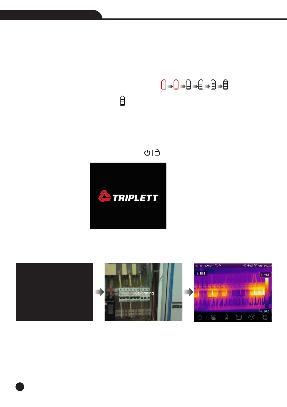
• The battery status shows on the six-segment charge indicator.
• To charge the battery, use follow before:
1.Connect the ac power adapter into an ac wall outlet and connect the dc output to the Thermal Imager’s ac power
socket, the charge light is on, The battery indicator becomes “ ” while the battery
charges with the ac power adapter.
2.Charge until the charge indicator becomes “ ”, the charge icon not changed.
3.Disconnect ac power adapter when the battery is full charged.
Note: Make sure that the Thermal Imager is near room temperature before you connect it to the charger. Do not
charge in hot or cold areas. When you charge in extreme temperature, battery capacity may be decreased.
5-2.Power On
To turn the Thermal Imager on, push the Power/Lock “ ” Button about 2 seconds.
Note: After power on the device, the thermal Imager needs sufficient warm-up time for the most accurate
temperature measurements and best image quality. So the visible image will first appear, and the thermal sensor
will calibrate internal for sevearal seconds. After that the thermal image will be displayed on the screen.
Professional thermal imager
Professional thermal imager
11
Thermal Imager
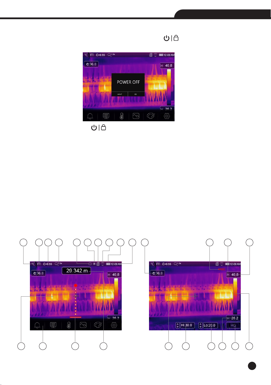
5-3.Power Off
• When Thermal Imagers power on, Push and hold the Power/Lock “ ” Button for two seconds, then popup
the power off menu, press “OK” to power off the device.
• Push and hold the Power/Lock “ ” Button for 7 seconds, the device will be forced power off directly.
5-4.Desktop
The Desktop is as follow:
1-Temperature Unit
2-Distance Unit
3-Emissivity
4-Zoom Quick Menu Entrance
5-Flashlight ON Status
6-Laser ON Status
7-SD Card
8-WiFi ON Status
9-Battery Capacity Status
10-Time
11-Image Display Area
12-Main Menu
13-Laser Distance Meter Indicator
14-Laser Distance Meter Readings
15-Centre Point Temperature Readings
16-Video Record Status
17-AGC Mode
18-Max Temperature of Current Scene
2 3 41
5
6 7 8 9
10
12
11 13 14
15 16
17
18
20
21
19 23
2422
19-Centre Point Cross
20-Manual adjust Max temperature of
current scene with up or down key
21-Manual adjust Min temperature of
current scene with up or down key
22-Min Temperature of Current Scene
23-AGC Mode Select Button
24-Color Bar
12
Thermal Imager
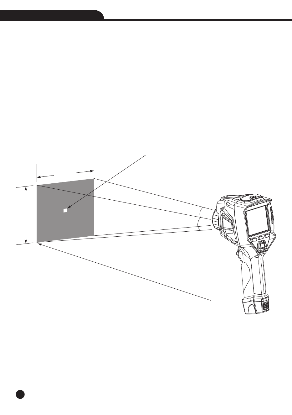
5-5.Lens
• The Thermal Imager has a Lens.
• FOV is the largest area that your imager can see at a set distance.
• This table lists the horizontal FOV, vertical FOV and IFOV for lens.
Focal Length
22mm
• IFOV (Instantaneous Field of View) is the smallest detail within the FOV that can be detected or seen at a set
distance, the unit is rad, The formula is this: IFOV=(Pixel Size)/(Lens focal length).
• D:S theoretical (=1/IFOV theoretical) is the calculated spot size based on the pixel size of the Thermal Imager
detector array and lens focal length.
Example: If Thermal Imager uses 22mm lens, because the Pixel Size of detector is 17µm, Horizontal FOV is 17°,
Vertical FOV is 12.7°, the IFOV is 17µm/22mm=0.77mrad; D:S theoretical (=1/ IFOV theoretical)=1298:1.
• D:Smeasure (=1/IFOV measure) is the spot size needed to provide an accurate temperature measure.
• Typically D:S measure is 2 to 3 times smaller than D:S theoretical, which means the temperature measurement
area of the target need to be 2 to 3 times larger than that determined by the calculated theoretical D:S.
Note: IFOV theoretical represents the smallest objects that the thermal imager can detect or see. IFOV measure
represents the smallest object form which an accurate temperature can be measured by the thermal imager.
IFOV
0.77mrad
Horizontal FOV
17°
Vertical FOV
12.7°
Spot Size=100.00cmx100.00cm
(Based upon IFOV theoretical)
384m
2
8
8
m
1298m
17°
12.7°
13
Thermal Imager
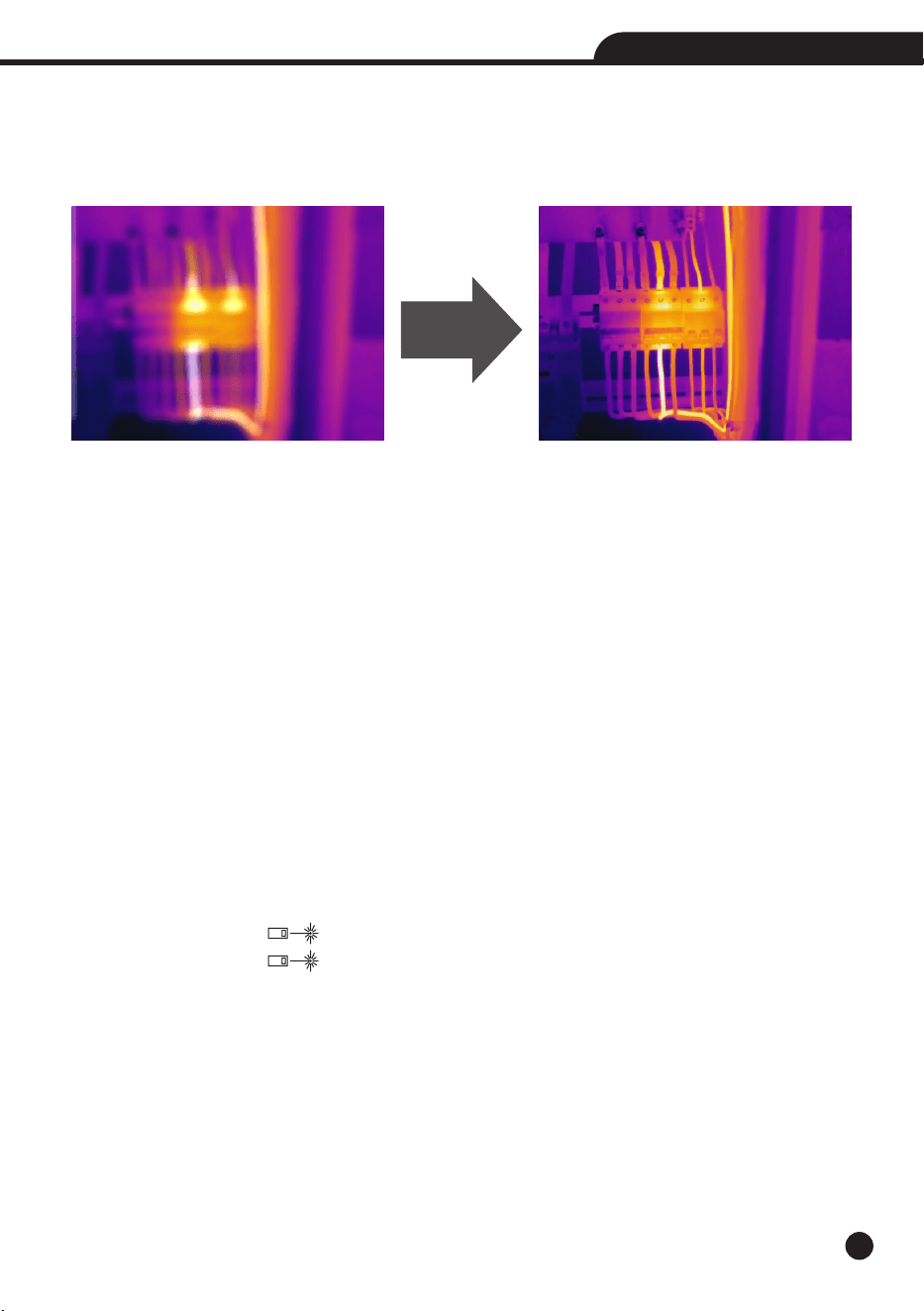
5-6.Focus
• To adjust focus, clockwise or Anti-clockwise rotates the IR Lens.
• When target comes into focus, it shows a sharper image.
• When the target moves out of focus, the thermal image becomes blurry.
Note: Correct focus is important in all imaging applications. Correct focus makes sure that the infrared energy is
correctly directed onto the pixels of the detector. Without the correct focus, the thermal image can be blurry and
the radiometric data will be inaccurate. Out-of-focus infrared images are frequently unusable or of little value.
5-7.Shutter
• The thermal image of the Thermal Imager becomes blurry, when the Thermal Imager no correcting after some
minutes or the Thermal Imager changes target.
• To get fine thermal image, the Thermal Imager need to correct.
• The Thermal Imager has two mode for correcting, Manual and Auto mode.
• In Manual Mode, long press the down arrow button, the Thermal Imager will correct.
• In Auto Mode, the Thermal Imager can correct automatically while The thermal image of the Thermal Imager
becomes blurry.
5-8.LED Light
In quick setting menu, press the flash light button, the LED light will be on or off.
5-9.Laser
• In desktop, long press the “ ” Button and hold about 2 seconds, the laser is on.
• In desktop, long press the “ ” Buttonand hold about 2 seconds again, the laser is off.
5-10.Temperature Measurement
• All objects radiate infrared energy.
• The quantity of energy radiated is base on the actual surface temperature and the surface emissivity of the object.
• The Thermal Imager senses the infrared energy from the surface of the object and uses this data to calculate an
estimated temperature value.
• Many common objects and materials such as painted metal, wood, water, skin, and cloth are very good at radiating
energy and it is easy to get relatively accurate measurements.
Focus to get
clear image

14
Thermal Imager
• For surfaces that are good at radiating energy (high emissivity), the emissivity factor is >0.90.
• This simplification does not work on shiny surfaces or unpainted metals as they have an emissivity of <0.6, These
materials are not good at radiating energy and are classified as low emissivity.
• To more accurately measure materials with a low emissivity, an emissivity correction is necessary.
• Adjustment to the emissivity setting will usually allow the Thermal Imager to calculate a more accurate estimate
of the actual temperature.
• More information please see Emissivity Adjustment to get the most accurate temperature measurements.
5-11.Emissivity Adjustment
• The correct emissivity value is important to make the most accurate temperature measurement.
• Emissivity of a surface can have a large effect on the apparent temperatures that the Thermal Imager observes.
• Understanding the emissivity of the surface, but may not always, allow you to obtain more accurate temperature
measurements.
Note: Surfaces with an emissivity of <0.60 make reliable and consistent determination of actual temperature
problematic. The lower the emissivity, the more potential error is associated with the Imager’s temperature
measurement calculations. This is also true even when adjustments to the emissivity and reflected background
adjustments are performed properly.
• Emissivity is set directly as a value or from a list of emissivity values for some common materials.
• The global emissivity displays in LCD Screen as E=x.xx.
The following table gives typical emissivity of important materials.
Material
Water
Stainless Steel
Aluminum Plate
Asphalt
Concrete
Cast Iron
Rubber
Wood
Brick
Tape
Brass Plate
Human Skin
PVC Plastic
Polycarbonate
Oxidized Copper
Rust
Paint
Soil
Emissivity
0.96
0.14
0.09
0.96
0.97
0.81
0.95
0.85
0.75
0.96
0.06
0.98
0.93
0.80
0.78
0.80
0.90
0.93

15
Thermal Imager
5-12.Reflected Temperature
• Using the offset factor, the reflection is calculated out due to the low emissivity and the accuracy of the
temperature measurement with infrared instruments is improved.
• In most cases, the reflected temperature is identical to the ambient air temperature.
• Only when objects with strong emissions with much higher temperature are in the proximity of the object being
measured should be determined and used.
• The reflected temperature has only little effect on objects with high emissivity.
• The reflected temperature can be set individually.
• Follow these steps to get the right value for the reflected temperature.
1.Set the emissivity to 1.0.
2.Adjust the optical lens to near focus.
3.Looking in the opposite direction away from the object, take a measurement and freeze the image.
4.Determine the average value of the image and use that value for your input of reflected temperature.
5-13.Thermal Imager Reporter Software
• Thermal Imager Reporter software is supplied with the Thermal Imager.
• This Software is intended for Thermal Imager and contains feature to analyze images, organize data and
information, and make professional reports.
• Thermal Imager Reporter software allows audio annotations and commentary to be reviewed on a PC.
16
Thermal Imager
6.Menus
The menus, together with buttons, are access for image, measurement, Emiss, Palette, temperature measurement
range, take photo and video, review, and settings.
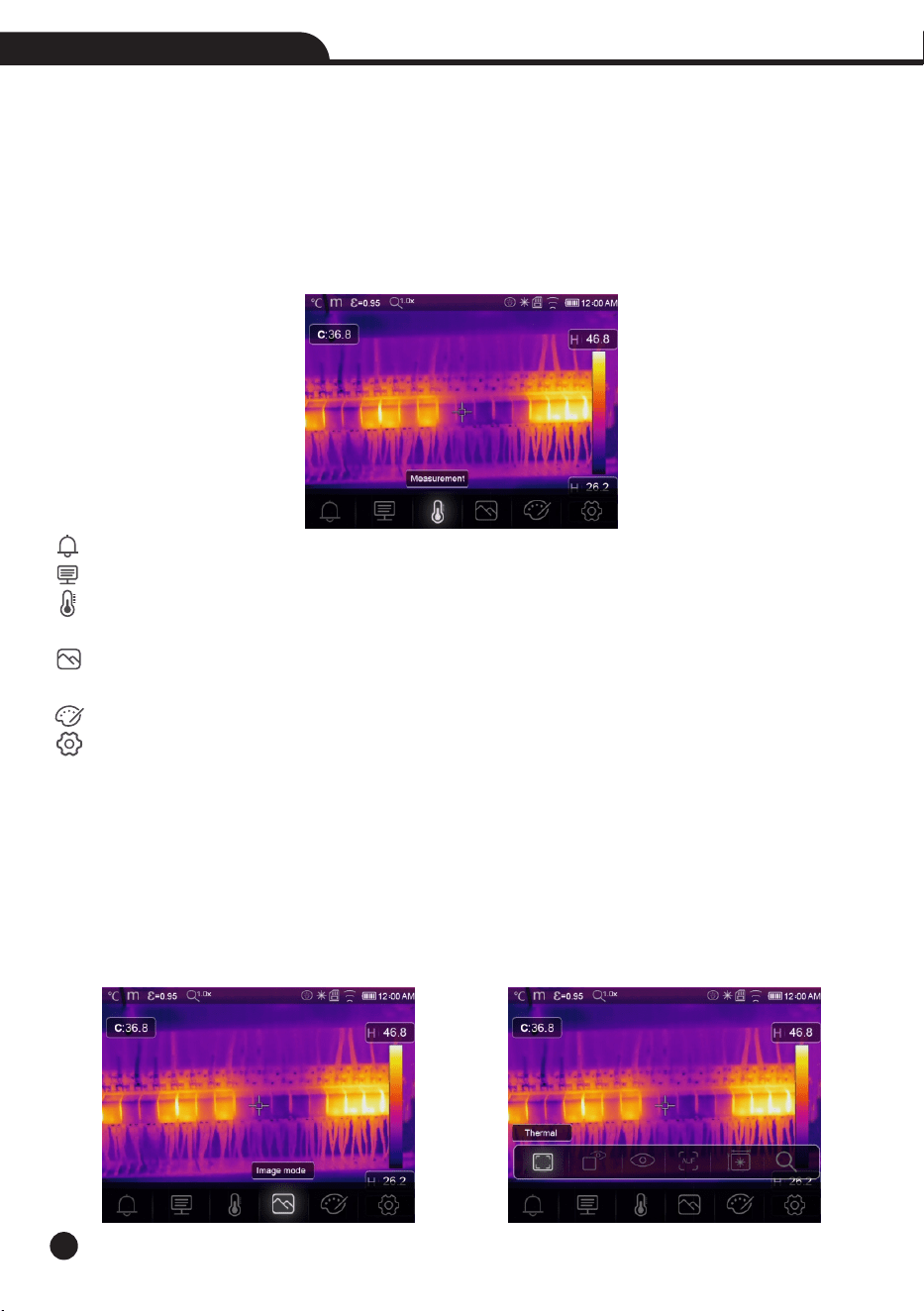
6-1.Main Menu
• Press “Menu/OK” Button or touch the screen, the main menu will be poped up.
• Main Menu is the main interface of the Thermal Imager’s menus.
• It contains five items such as Measure parameters, Measure tools, Image mode, Palette, system Settings.
Alarm: Set alarm temperature.
Paramters: Parameters set for the calculation temperature.
Measure Tools: Set for the calculation and display of radiometric temperature measurement data related to
the thermal images.
Image Mode: Set image source for the display on the Thermal Imager’s LCD. It contains five items such as
infrared image, visual image and fusion.
Palette: Set the type of color bar.
Settings: Set for the user preferences such as language, unit of temperature measurement, date, time;
restore factory setting and display product information.
6-2.Image Mode
1.In main menu, press “Image Mode” icon button, highlight “Image Mode”.
2.Press “Up” button, popup Image submenu which contains five image modes.
3.Press “Left” or “Right” button, or touch the image mode icons, highlight the Image mode which you want to
choose.
4.The image mode will change after you choose it.
17
Thermal Imager
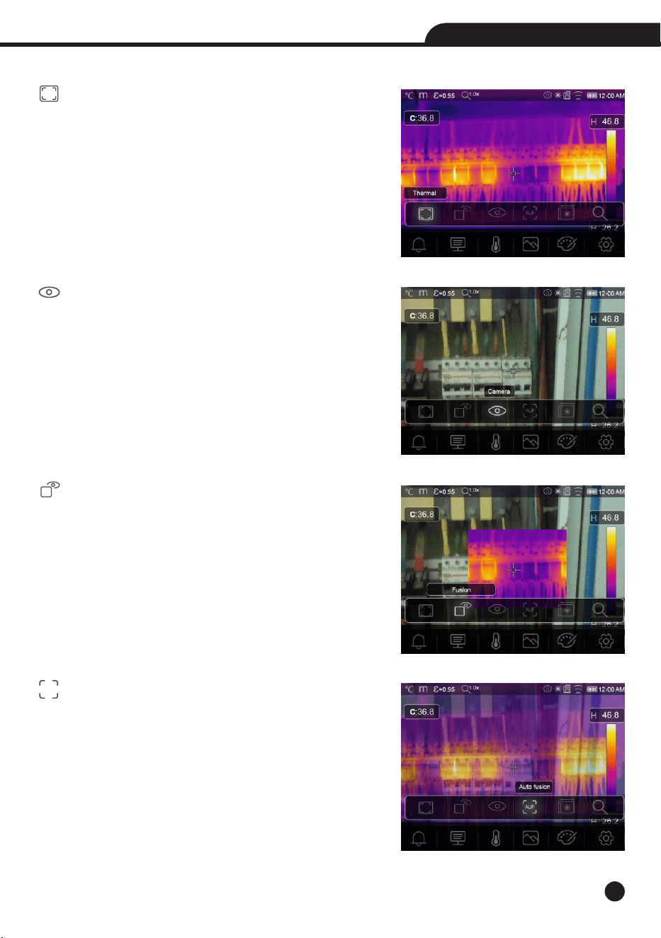
5.Thermal Imager has 6 kinds of image modes for display: IR, Camera, Fusion, AUF mode, LDM, Zoom Mode.
IR: Displays only infrared image.
Camera: Displays only visible image.
Fusion: Display fusion image of infrared and visible images.
AUF: Auto Fusion mode, compare the centre area temperature
with full screen, the machine will calculate the mix ratio of
infrared and visible images automaticly.
AUF
18
Thermal Imager
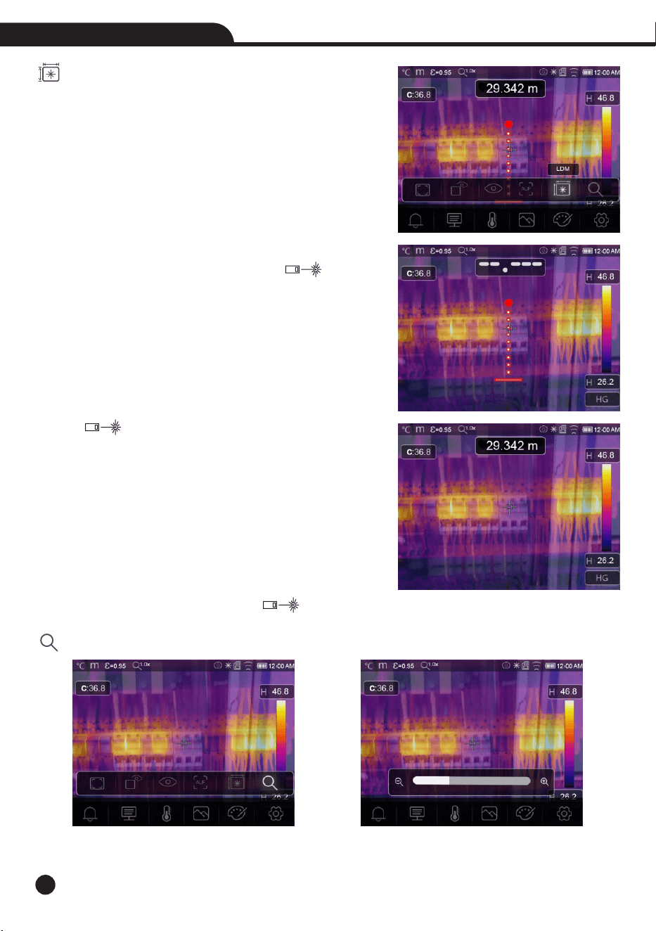
LDM Mode: This mode use laser distance meter to get object
distance.
• In the Laser distance meter mode, it can measure the distance
between the object and the device, Press the “ ” button
the laser will opened, and the device is ready for measure.
• Press “ ” again, the distance value will displayedand the
image will freeze for you to review.
• Press “OK” to save the picture, or press “ ” to release the image.
Zoom Mode: Set the image zoom in or zoon out.
19
Thermal Imager
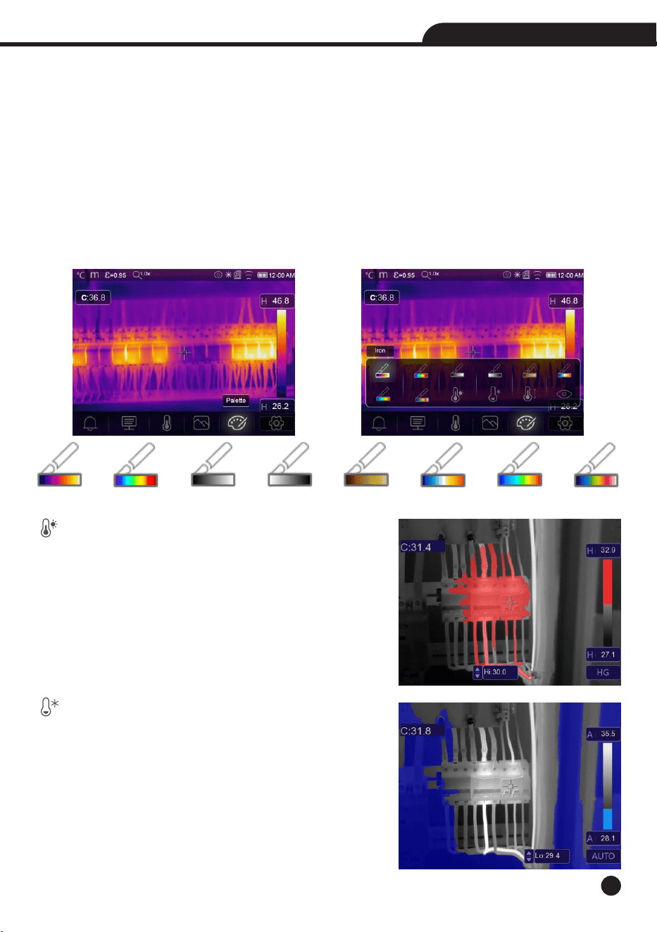
Iron Rainbow White Hot Black Hot Brown Hot Blue Red Hot Cold Feather
6-3.Image Palette
• The Image Palette lets you change the false-color presentation of the infrared images on display or captured.
• A variety of palettes are available for specific applications.
• The standard palettes offer an equal, linear presentation of colors that allow for best presentation of detail.
Standard Palette
1.In main menu, press “Palette” icon button, highlight “Palette”.
2.Press “Up” Button, popup Image submenu which contains 8 kinds of color palettes and 4 kinds of special
palettes.
3.Press “Left” or “Right” Button, or touch the image mode icons, highlight the palette which you want to choose.
4.The palette mode will be changed after you choose it.
Above Alarm: The temperature higher than the high alarm
set value will be colored to red, press the Hi: 30.0 value button
to adjust the above temperature.
Below Alarm: The temperature lower than the low alarm
set value will be colored to blue, press the Lo: 29.4 value
button to adjust the below temperature.
20
Thermal Imager
Zone Alarm: The temperature between the high alarm and the low alarm set value will be colored to orange.
Visible Zone: The temperature between the high alarm and the low alarm set value will be colored to the
palette, other part of the image will displayed as visible image.
6-4.Image Adjustment
There are three kinds of mode for image adjustment, hisgram, Auto and Manual.
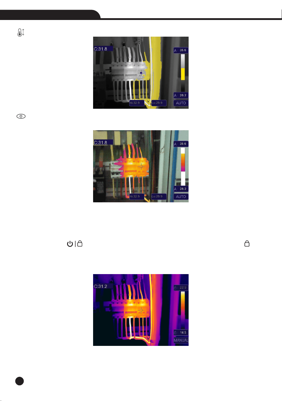
6-4-1.Lock Operation
• Press Power/Lock “ ” Button button to quickly to lock the current scene temperature range, “ ”means
Manual.
• After locked the current scene temperature range, press the locked value button to adjust the lock temperature,
you can adjust the high/low temperature level to see what temperature your interested range image.
21
Thermal Imager
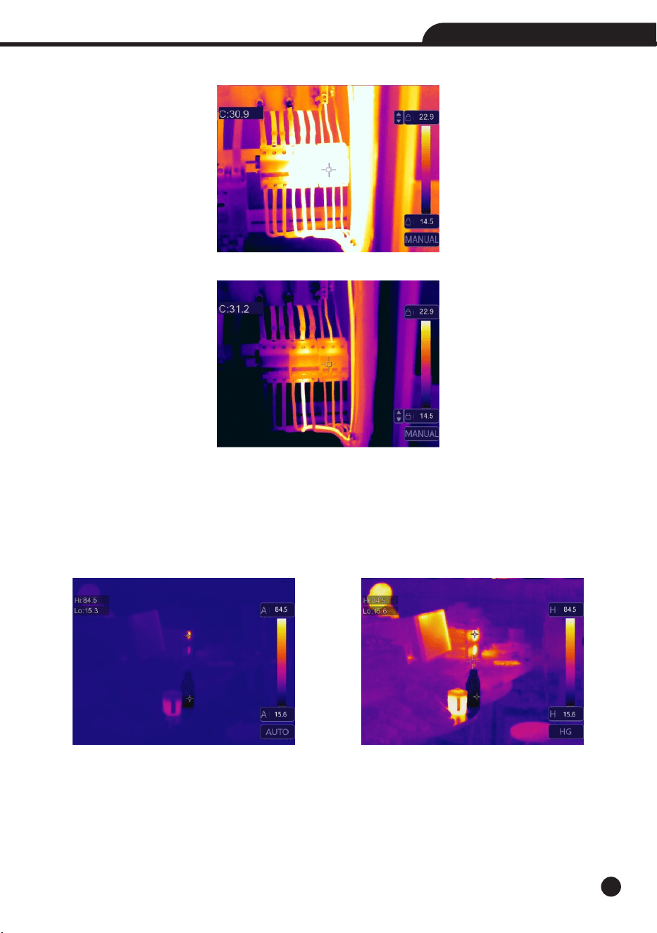
Lock the low level and adjust the high level of the temperature range:
Lock the high level and adjust the low level of the temperature range:
6-4-2.Histgram Mode and Auto Mode
• Auto Mode: level and span are decided by the thermal image of minimum temperature and maximum temperature,
The relationship between temperature and color is linear.
• Histgram Mode: the thermal image is enhanced by histogram algorithm, The relationship between temperature
and color is not linear, Some part of the image is enhanced.
• Touch the icon “HG” or “AUTO” below the colorbar to change the mode.
22
Thermal Imager
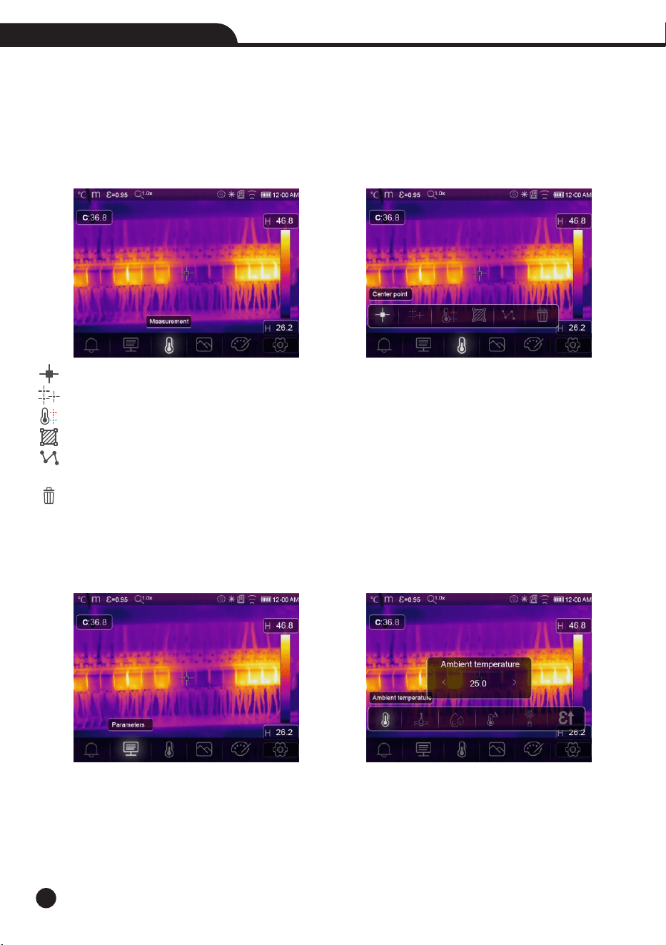
6-5.Measurement Menu
1.In main menu, press “Measurement” icon button, highlight “Measurement”.
2.Press “Up” button, popup Image submenu which contains 5 kinds of Measurement tools.
3.Press “Left” or “Right” button, or touch the Measurement tools icons, highlight the Measurement tool which
you want to choose.
4.The Measurement tool will be enabled after you choose it.
Center Point: Measure the center point temperature.
Measure Point: Measure the manual point temperature, There are three manual analyse points.
Hi/Lo Spot Analsye: Capture max/minimum temperature.
Area Analsye: Measure the area temperature, There are three analyse areas.
Line Analsye: Measure the line temperature, There are two analyse lines, One for horizontal, the other is
vertical line.
Delete all Analsye: Delete all analyse tools.
6-6.Parameter Menu
In main menu, press “Up” and “Down” button, highlight “Emiss”, press “Select” button, popup object parameter
submenu.
23
Thermal Imager
6-6-1.Ambient Temperature Composation
• In Ambient temperature submenu, press “Left” and “Right” arrow to change the temperature values.
• Ambient temperature will affect the measurement of the thermal imager, it can be composite from -10 to 50
degree.
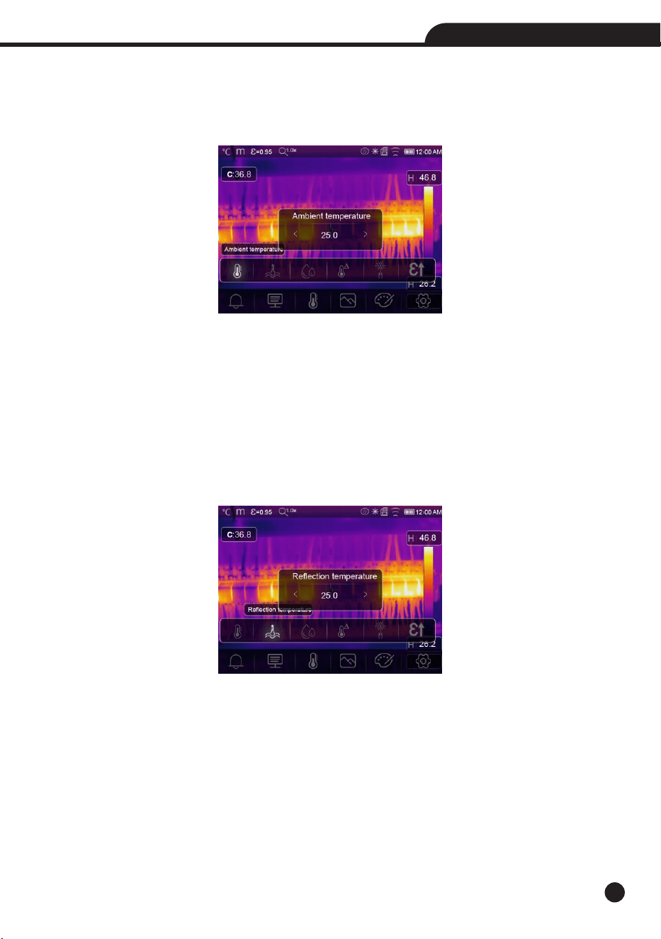
6-6-2.Reflective Temperature
• In reflective temperature submenu, press “Left” and “Right” arrow to change the temperature values.
• The reflective temperature is important for radiometric temperature measurement, Thermal Imager has
temperature compensation for reflective temperature.
• To get more accurate temperature measurement, accurately set the reflective temperature.
• In most cases, the reflected temperature is identical to the ambient temperature.
• Only when objects with strong emissions with much higher temperature are in the proximity of the object being
measured, the reflected temperature must set.
24
Thermal Imager
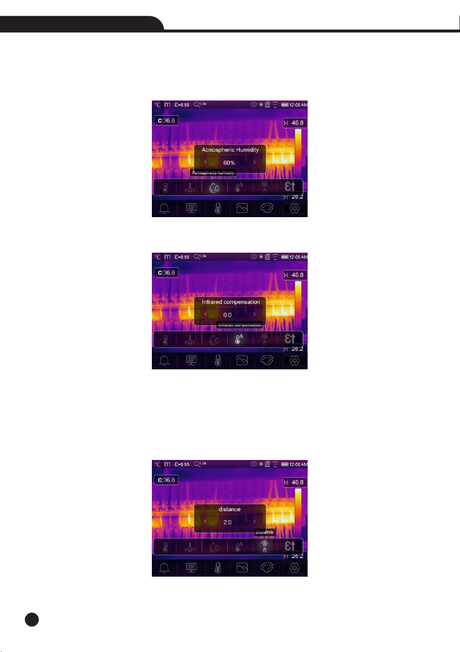
6-6-3.Atmospheric Humidity
• In Atmospheric humidity submenu, press “Left” and “Right” arrow to change the temperature values.
• Water droplets in the air can absorb infrared rays, The wet air can affect the measurement of the temperature’s
accurate, the compensation humidity can be set from 0%~100%.
6-6-4.Delta Temperature Compesation
In delta temperature submenu, press “Left” and “Right” arrow to change the temperature values.
6-6-5.Distance
• In distance submenu, press “Left” and “Right” arrow to change the distance values.
• There are many substances in the air that can absorb infrared rays, So the infrared ray of the object will decaied
as the distance increase.
• The distance can be setted from 0 to 2000 meters.
25
Thermal Imager
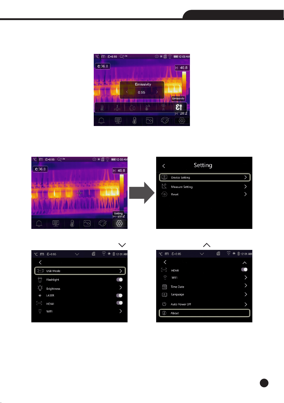
6-6-6.Emissivity
• In emissivity submenu, press “Left” and “Right” arrow to change the emissivity values.
• “Emiss” sets object emissivity, the value range is 0.01~1.00.
6-7.Settings Menu
1.In main menu, press “Settings” icon button, highlight “Settings”.
2.The Settings menu will display.
6-7-1.Device Setting
There are multipages in Device setting, use “ ” icon to go to next page, or use “ ” to go to previous page.
USB Mode:
• PC Connection: Set the device as Mass storage mode, if connect the device to the PC with USB cable, there will
be a Mass storage device on the PC.
• PC Camera: Set the device as UVC camera mode, if connect the device to the PC with USB cable, there will be a
UVC camera device on the PC.
26
Thermal Imager
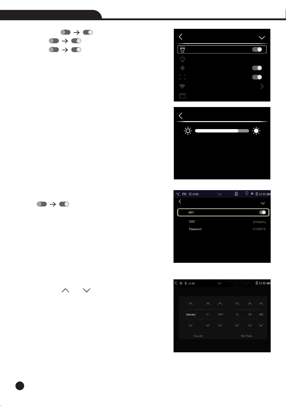
Flashlight: Press “ ” “ ” to turn on the flash light. Laser:
Press “ ” “ ” to turn on the Laser.
HDMI: Press “ ” “ ” to turn on the HDMI output.
Brightness: Drag the slider bar to adjust the LCD brightness.
WIFI:
• Press “ ” “ ” to turn on the wifi, the wifi model worked
on access mode, so it is need to set the SSID and Password to
allow other device connect to it.
• The default SSID is “xxxxxxxx”, the default password is
“12345678”.
Time Date : Press “ ” or “ ” to change time/date, then press
“Set Date” to save the change, or press “Cancel” to quit.
Brightness
Device Setting
Flashlight
Brightness
LASER
HDMI
WIFI
Time Date
HDMI
23
27
Thermal Imager
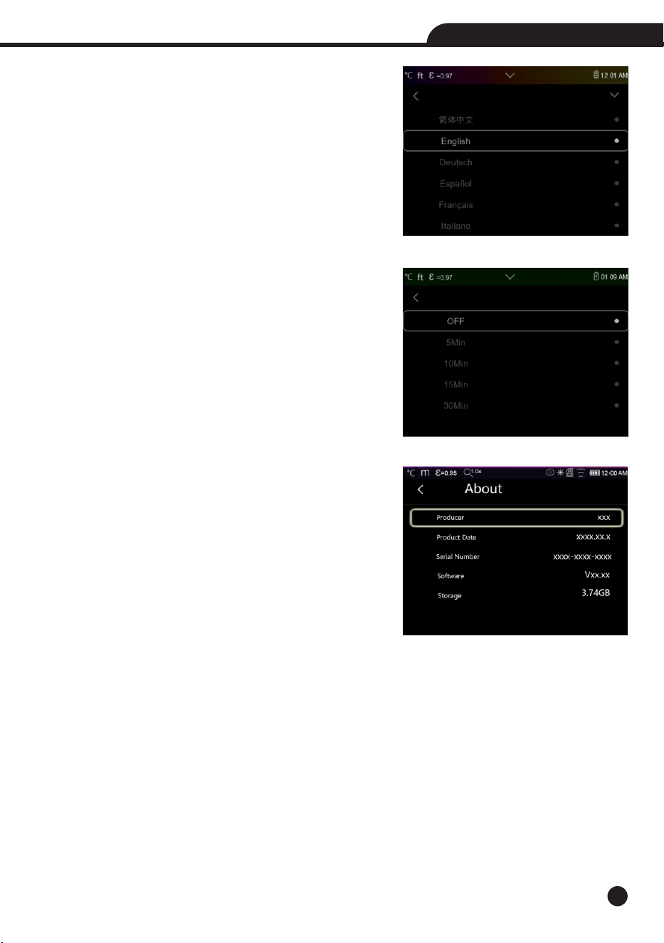
Language: Press “Up/Down” Button to to select language and use
“MENU/OK” Button to set selected language to be valid.
Auto Power Off
• Thera are four options in auto power off menu, as follows: “OFF”,
“5Min”, “10Min”, “15Min”, “30Min”.
• When press the touch screen or keyboard, the timer of Auo Power
Off will be cleared and re-timed.
About: The info menu contains all of the product information, such
as: Software Version, Serial Number and so on.
28
Thermal Imager
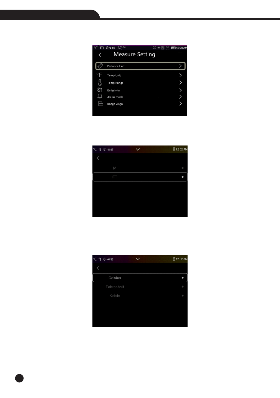
6-7-2.Measure Setting
Thera are four options in Measure setting menu, as follow picture.
Distance Unit
• Change the distance unit between “m” and “ft”, “m” means meter, ft means Foot.
• 1(ft)=0.3048(m); 1(m)=3.2808399(ft).
Temperature Unit
• Temperature Unit have three types to choose: °C,°F and K.
• Conversion relationship: °F=1.8 x °C+32, K=273.15+°C.
29
Thermal Imager
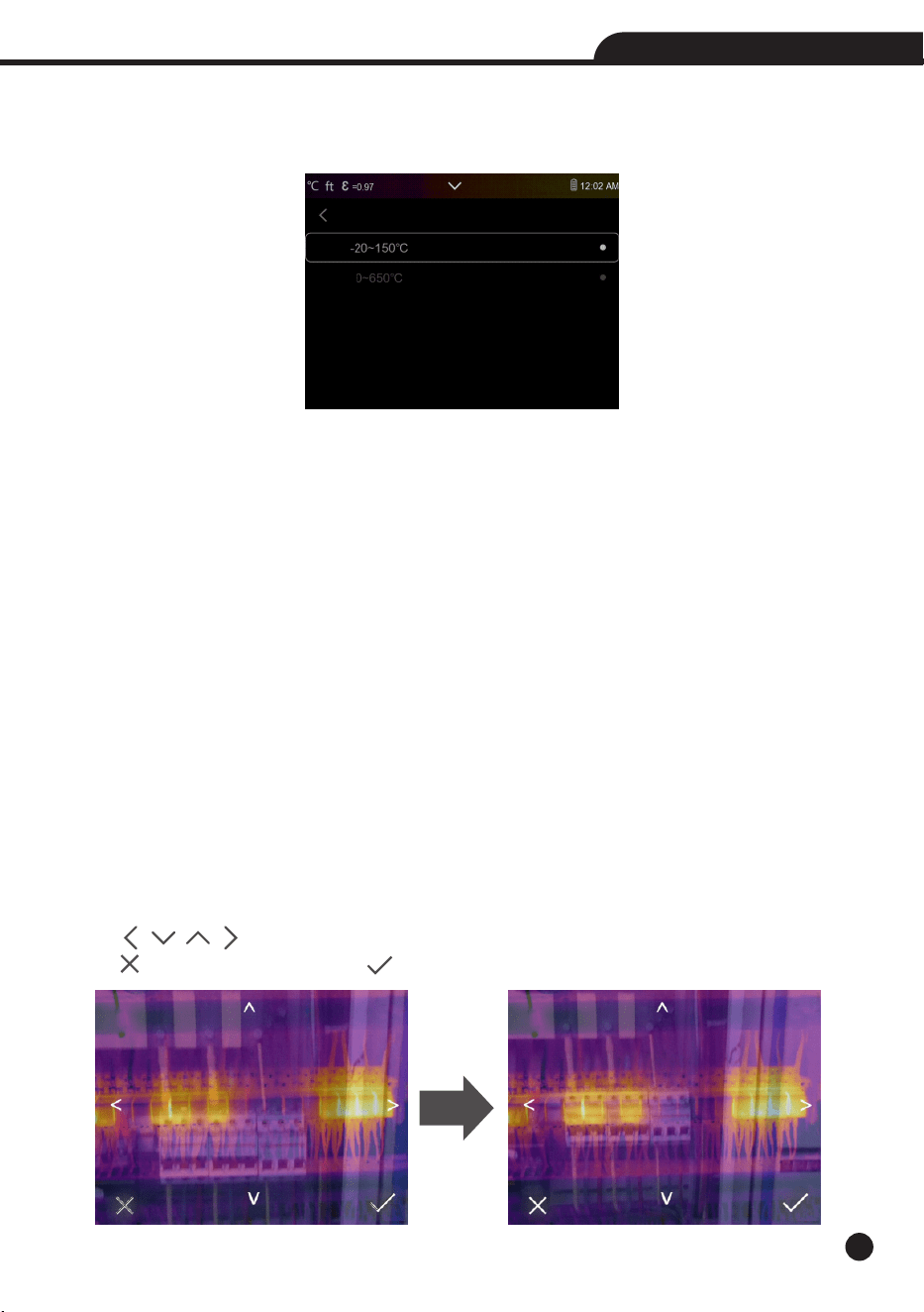
Temperature Range
• The temperature measurement ranges have “-20~150°C” and “0~650°C” to choose.
• The overlap temperature of the two ranges is more accurate to choose “-20~150°C”.
Emissivity: Quick set the emissivity from the table below:
Material
Water
Stainless Steel
Aluminum Plate
Asphalt
Concrete
Cast Iron
Alarm Mode
• OFF: Turn off the alarm display and sound.
• Above Alarm: If the temperature of the object exceeds the above alarm value, there will be alarm sound and
display.
• Below Alarm: If the temperature of the object below the low alarm value, there will be alarm sound and display.
• Zone Alarm: If the temperature of the object between the low alarm value and the above alarm value, there will
be alarm sound and display.
Image Align
• Press “ ” to adjust the vision’s position to align the vision and infrared.
• Press “ ” to cancel the setting, press “ ” to save the aligment setting.
Material
Rubber
Wood
Brick
Tape
Brass Plate
Human Skin
Emissivity
0.96
0.14
0.09
0.96
0.97
0.81
Emissivity
0.95
0.85
0.75
0.96
0.06
0.98
Material
PVC Plastic
Polycarbonate
Oxidized Copper
Rust
Paint
Soil
Emissivity
0.93
0.80
0.78
0.80
0.90
0.93

30
Thermal Imager
Parameter
Center Spot Measurement
Hot Spot Measurement
Cold Spot Measurement
Emissivity
Reflective Temperature
Mode
Palette
Adjustment
Language
HDMI Output
Laser
Lamp
6-7-3.Reset
Format Memory: Format Memory operation will format all the
Picture Gallery, the device setting is not affected.
Factory Settings
Factory Settings of the Thermal Imager is as follow:
Item
Measurement
Measurement Parameters
Image
System Setting
Value
off
off
off
0.95
25°C
Infrared
Iron
Auto
English
off
off
off
Format Memory?
No Yes
Factory Setting
No Yes
31
Thermal Imager
6-8.Camera Menu
• Thermal Imager has photo and video functions.
• In photo function, the Imager can save thousands of images.
• Every image resolution is 1280x960, format is “.jpg”, and stores infrared data and visible data in an image.
• In video function, the Imager has “.mp4” video capture for hours, and save infrared data in “.mp4” format.
Note: Images and video files are stored in SD Memory Card, Images can easily be read and second analyzed within
Thermal Imager PC software.
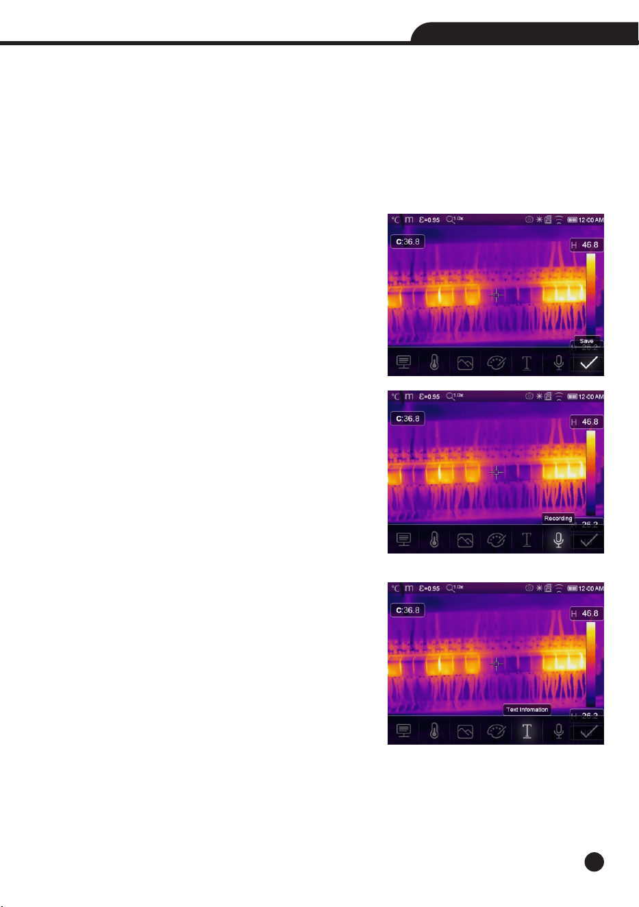
Save Image
1.In desktop, press Trigger button, freeze an image, the save menu
will display.
2.Press “Menu/ok” key save image, and the image will flash for a
second, after the image is saved, the image will be unfreezed.
Add Voice Recording
Touch the “Recording” icon, it can add voice infomation into the
picture.
Add Text Note
• Touch the “Text information” icon, it can add some text infomation
into the picture.
• Next time if the saved picture opened in gallery or PC software,
the text info will displayed with the picture.
32
Thermal Imager
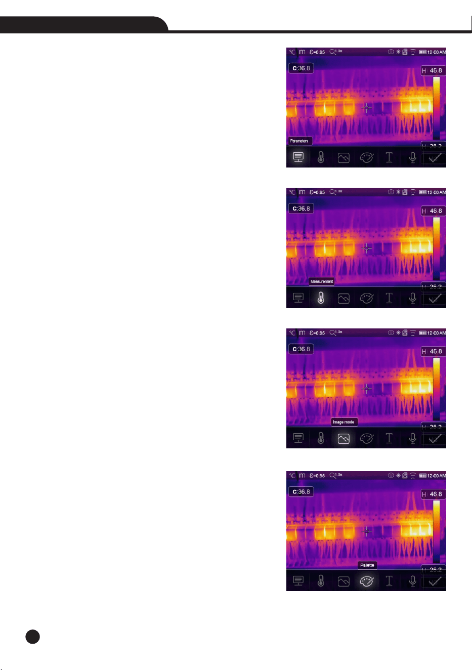
Change Measure Parameters
Touch the “Parameters” icon, it can change the image’s measure
parameters: Emissivity, Ambient Temperature, Humidity, Reflect
Temperature, Infrared Compensation, Distance.
Add Analyse Tools
Touch the “Measurement” icon, it can add or change the analyse
tools in the image: Point Analyse, Area Analyse, Line Analyse.
Change Image Mode
Touch the “Image mode” icon, it can change the image mode:
Thermal, Visible, Picture in Picture, Auto Fusion, Zoom.
Change Color
Touch the “Pallete” icon, it can change the image color.
33
Thermal Imager
6-9.Video Menu
The Thermal Imager has “.mp4” video capture.
1.In desktop, press Trigger button and hold for about 2 seconds, start video capture with voice.
2.To stop video capture, press Trigger button again, the video saved in the video file.
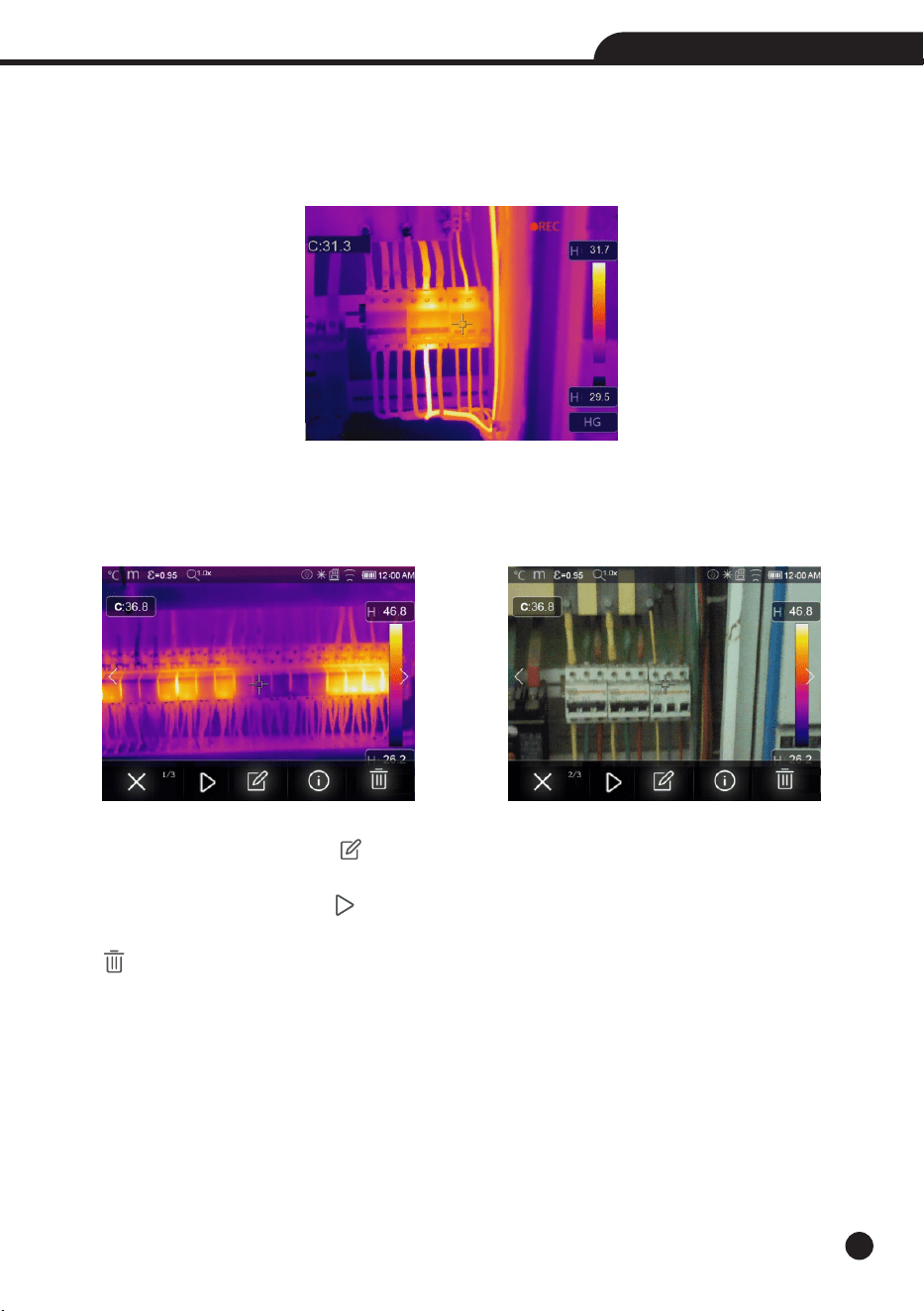
6-10.Files Browser
In desktop, press “Files Browse” button, popup files Browser, Which displays images and videos saved in SD
Memory Card.
Analyse an Image
When current file type is image, press “ ” to enter image analysis mode.
Play a Video
When current file type is video, press “ ” to play video.
Delete a File
press “ ” to delete the current file.

34
Thermal Imager
6-11.USB Mode
• Connect USB cable to device, popup the menu as follow:
• There are two modes for USB, Storage and PC Camera.
• Press up or down button to switch mode.
6-12.HDMI Output
• The video output available in the Thermal Imager enables displaying the thermal image (Not includes operator
menu) on an external monitor or video recording device capable of managing HDMI systems.
• To connect the Thermal Imager, proceed as follows:
1.Connect the Thermal Imager to the external HDMI monitor or recording device using the HDMI video cable provided.
2.Turn on the external HDMI monitor or device.
3.Power on the Thermal Imager.
4.With the image displayed on the external HDMI monitor or device, the thermal imager’s display works
simultaneously.
5.Once the operations on the external device are finished, Switch off the extern device and disconnect the HDMI
video cable from the thermal imager.
USB CONNECTED
35
Thermal Imager
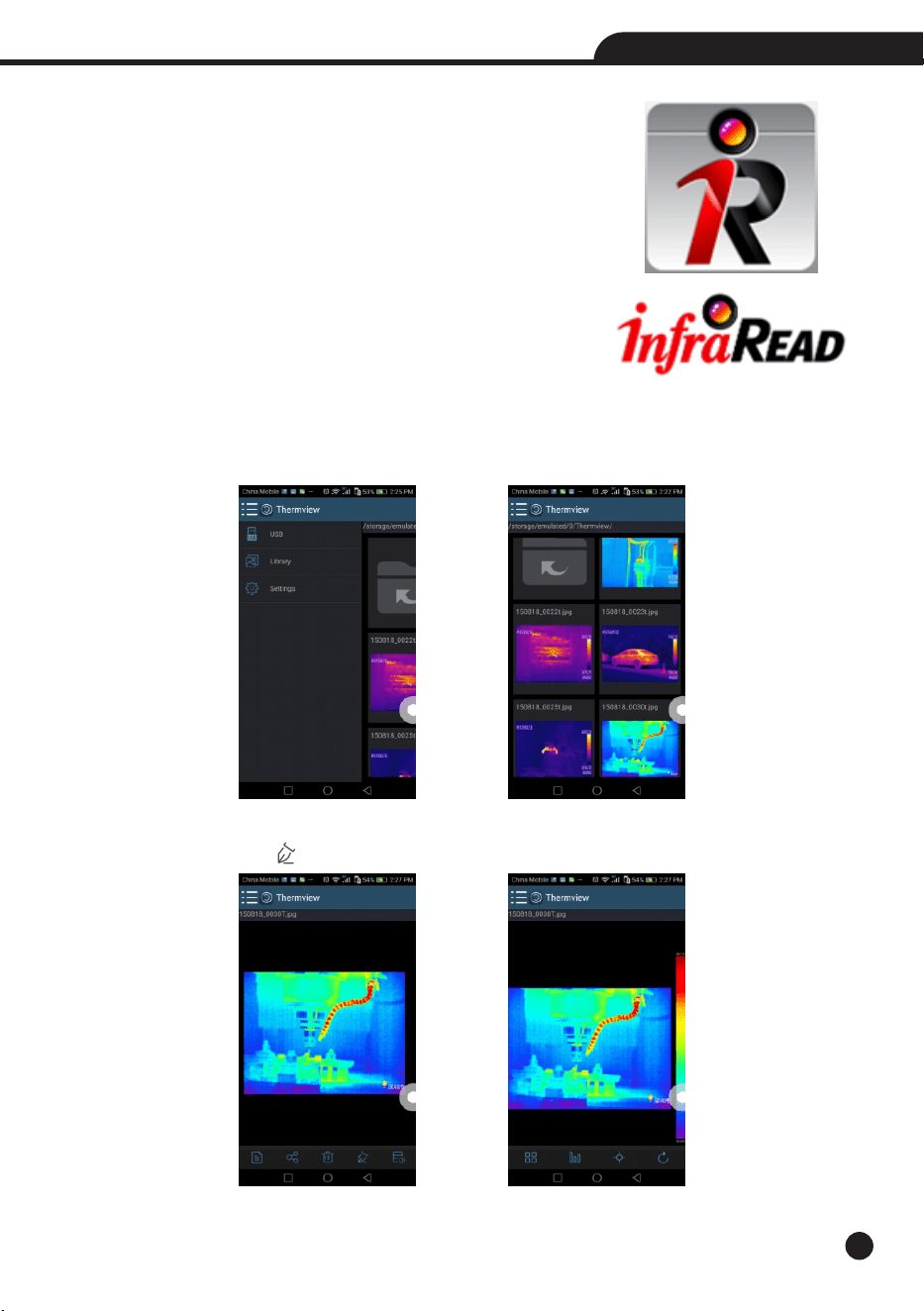
7.Android/iOS APP InfraRead
7-1.Software Install and Uninstall
7-1-1.System Required
Android mobile phone: Android 4.0 above, with USB OTG Support
iOS: iPhone4 above
7-1-2. InfraRead App Install
Android: Search “Thermview” on Google Play and install it.
iOS:
Search
“Thermview”
on
Apple
Store
and
install
it.
7-2.
InfraRead Function
7-2-1.Import Pictures
1. Use the USB OTG cable download the IR pictures from the thermal imager directly.
2. Copy the IR pictures from PC or SD card.
7-2-2.Analyse
Select a IR Picture and click “ ” icon to analyse it.
36
Thermal Imager
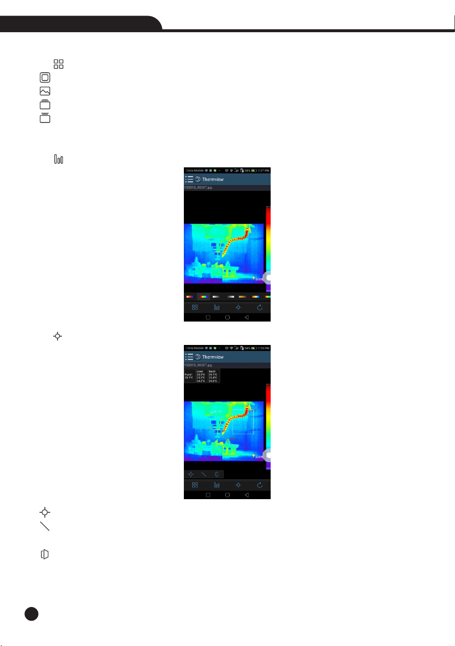
1.Image Mode
Click “ ” icon to select image mode, there are four mode for you to select.
(1) IR Mode: only infrared picture displayed.
(2) Visible Mode: only visible picture displayed.
(3) IR Fusion Mode: The infrared picture is fusioned with visible picture.
(4) Visible Fusion Mode: full screen fusion, the visible picture is fusioned with infrared picture.
2.Colorbar Select
Click “ ” icon to select colorbar. There are eight colorbar for you choice.
3. Analyze
Click “ ” icon to analzye the IR pictures. There are three analyse tools:
(1) Point Analysis: Add a point to the picture, it will display the temperature of the point.
(2) Line Analysis: Add a line to the picture, it will display the highest, lowest and average temperature of
the
line.
(3) Area Analysis: Add a rectangle to the picture, it will display the highest, lowest and average temperature
of
the rectangle.
37
Thermal Imager
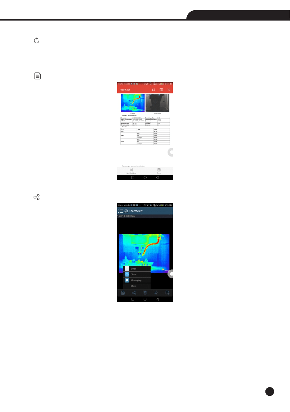
4.Save and Exit
Click “ ” to save and return to the main page of the APP.
7-2-3.Report and Share
1.Report
Click “ ” icon to report as a “.pdf” file.
2.Share
Click “ ” icon to share the Infrared picture with Email, Cloud or Message and so on.
38
Thermal Imager
8.PC Software
8-1.System Required
• Window 10 or higher version of Windows system.
• Please make sure you have installed Net Framework 4.6 when you install Thermview Pro software.
• If not, please find and install our Microsoft. NET_Framework_v4.6.exe that provided to you .
• Ppen the net framework 4.6, Follow all tips to install Net Framework 4.6 till it finishes.
• If your system already have installed Net Framework 4.6, then no need to install again.
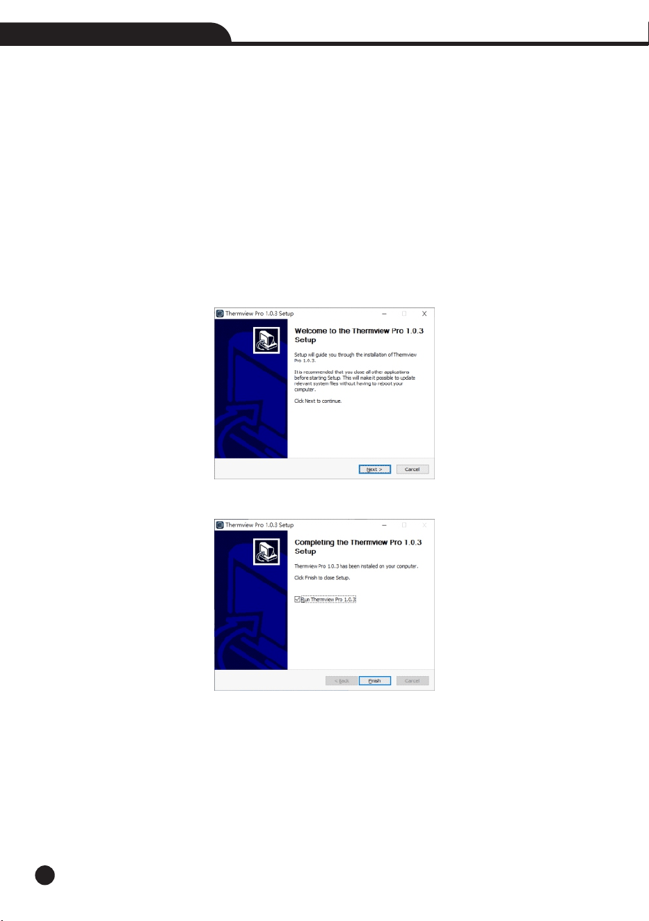
8-2. InfraRead Pro Install
• You can insert your installation CD to install directly if you have one, or you can run “setup.exe” to install it as
follow.
• Click “Next” to install, till finish installation.
• Installation Successful after click “Finish” like above.
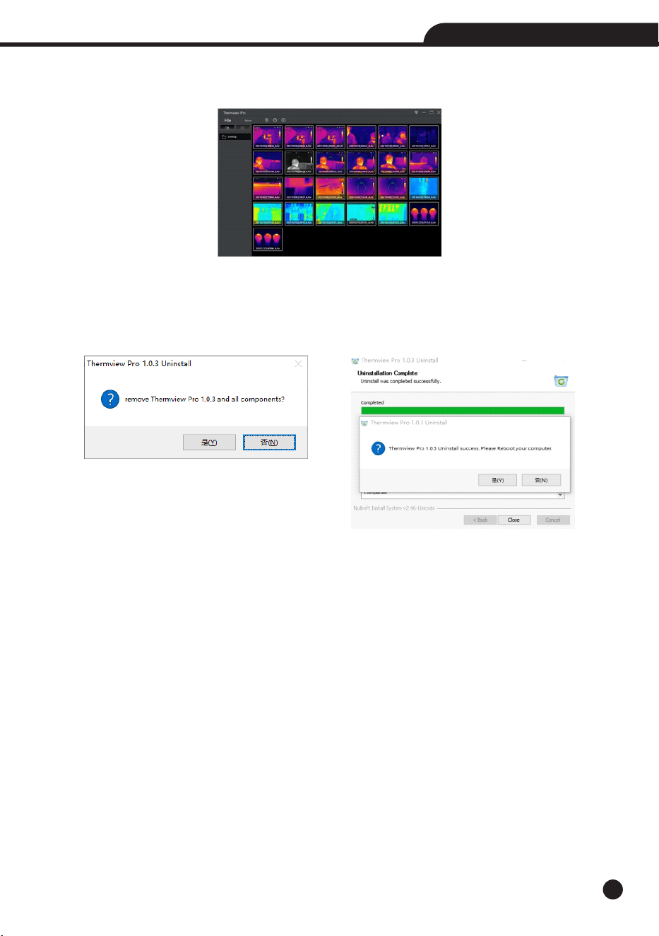
8-3.Running
After ensuring Infraread software has been installed, click shortcuts on the desktop to run the software.
8-4.Uninstall
• Uninstall Thermview Pro in the Installation directory as follow.
• Run “uninst.exe” and then click “YES” to start to uninstall, and finally choose whether to reboot the computer.
9.Fault Diagnosis and Exclusion
• If you encounter any problems while using the thermal imager, overhaul according to the following table.
• If the problem persists, disconnect the power and contact with the company’s technical support department.
Phenomenon of the fault
Thermal imager cannot start
Thermal imager shut down
No Thermal image
Cause of the fault
No battery
No power
No power
The lens cap cover
Solution
Inserting the battery
Replace the battery or charge it
Replace the battery or charge it
Opened the lens cap
39
Thermal Imager
Rev.250117
Thermal Imager