
- 1 -
WINCH MOUNT
MODEL:1910
- 2 -
MODEL:1910
This is the original instruction, please read all manual instructions carefully
before operating. VEVOR reserves a clear interpretation of our user
manual. The appearance of the product shall be subject to the product you
received. Please forgive us that we won't inform you again if there are any
technology or software updates on our product.
WINCH MOUNT

- 3 -
IMPORTANT SAFEGUARDS
WARNING: Read and understand this entire manual before
operating or servicing this product. Failure to follow these
warnings and instructions can cause personal injury or damage
to valuable property.
1.Assemble only according to these instructions. Improper assembly can
create hazards.
2.Wear ANSI-approved safety goggles and heavy-duty work gloves during
assembly and use.
3.Keep the assembly area clean and well-lit.
4.Keep bystanders out of the area during assembly.
5.Do not assemble when tired or when under the influence of alcohol,
drugs or medication.
6.Product capabilities apply to properly and completely assembled product
only.
7.For additional information regarding the parts listed in the following
pages, please refer to the Assembly Diagram of this manual. Unwrap and
separate all parts in a clean work area. Please keep small spare parts out
of children's reach.
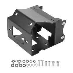
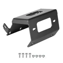
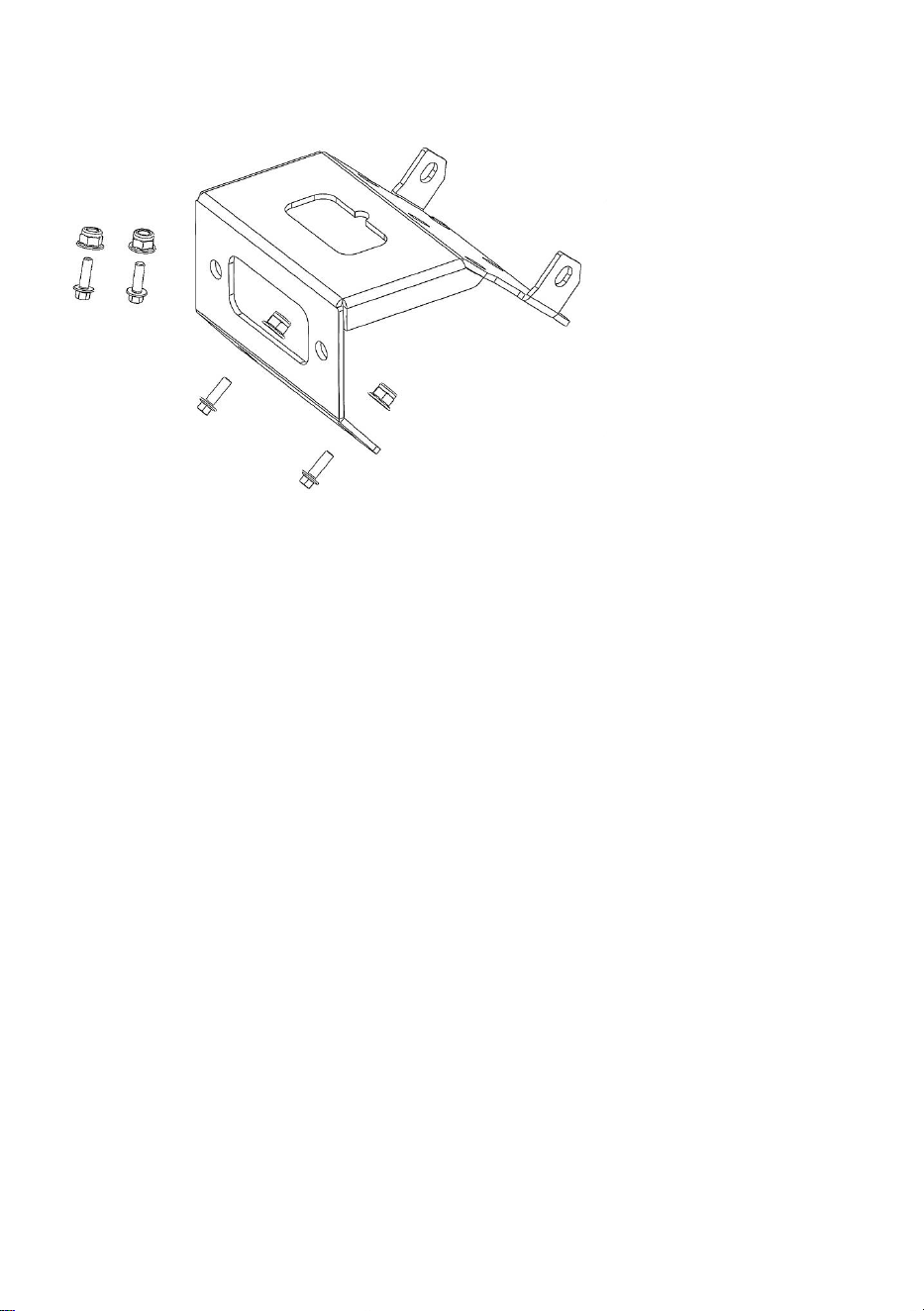
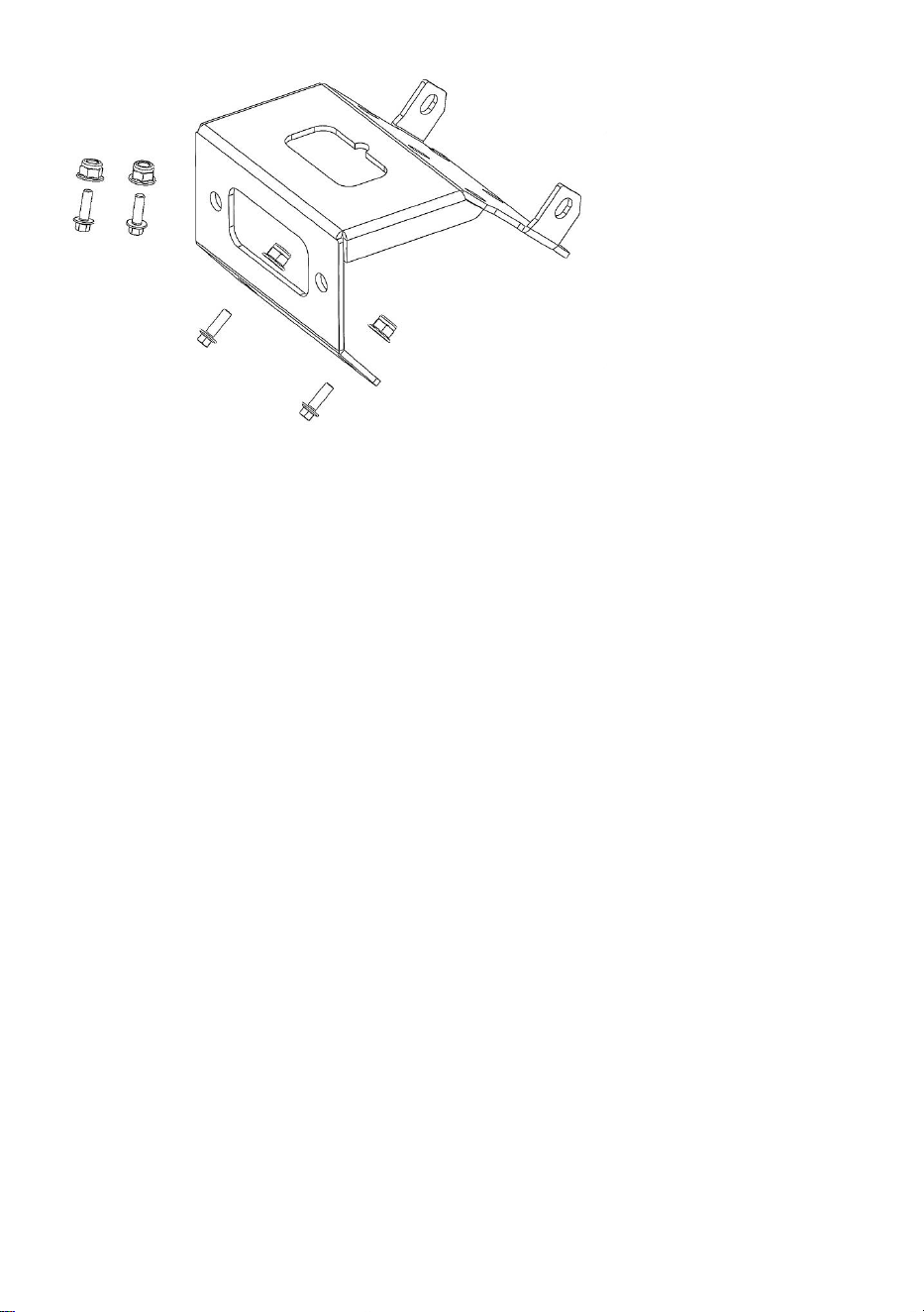
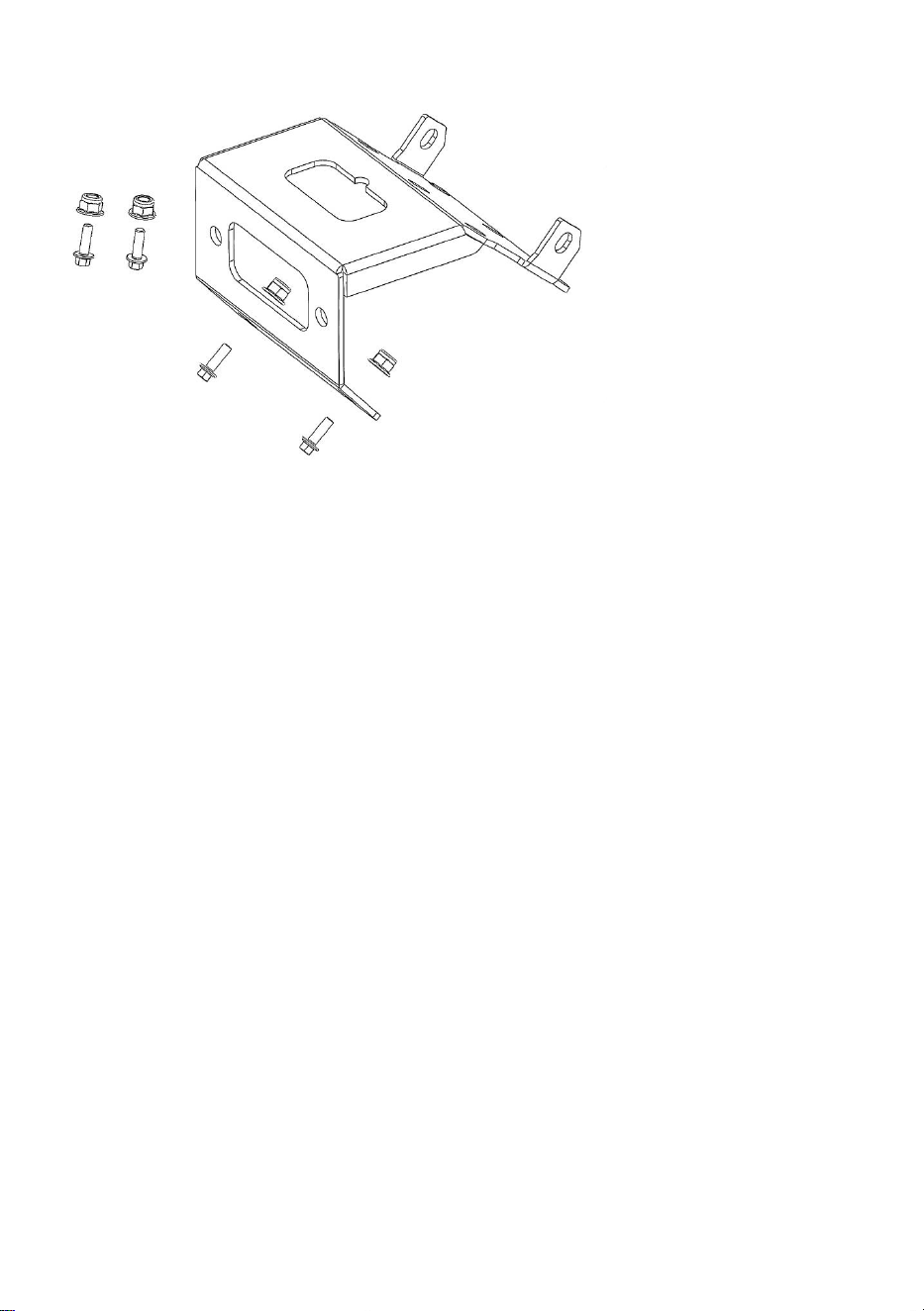
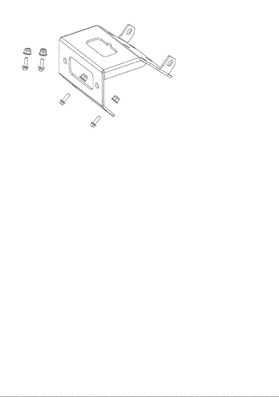
PACKAGE CONTENTS
Part
Description
QTY
1
WINCH MOUNT
1
2
M8*20 flanged hex bolt
4
3
M8 nuts
4

- 4 -
BEFORE INSTALLATION:
1.Switch off the vehicle and engage the parking brake.
2.Find the battery compartment. Disconnect the battery cables by
removing the negative terminal first, followed by the positive terminal.
INSTALLATION INSTRUCTIONS:
1.To remove or loosen the ATV's skid plate, undo the two bolts located at
the top of its sidewall.
2.The bumper is secured to the frame with 8 bolts: two at the top, two
inside the fender close to the headlight pod, and four near the front
suspension arm mounts (two on each side). Once all bolts are removed,
take off the front bumper and place it in a clean work area.
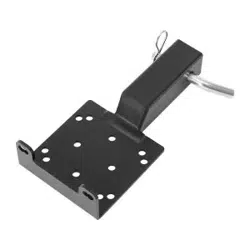
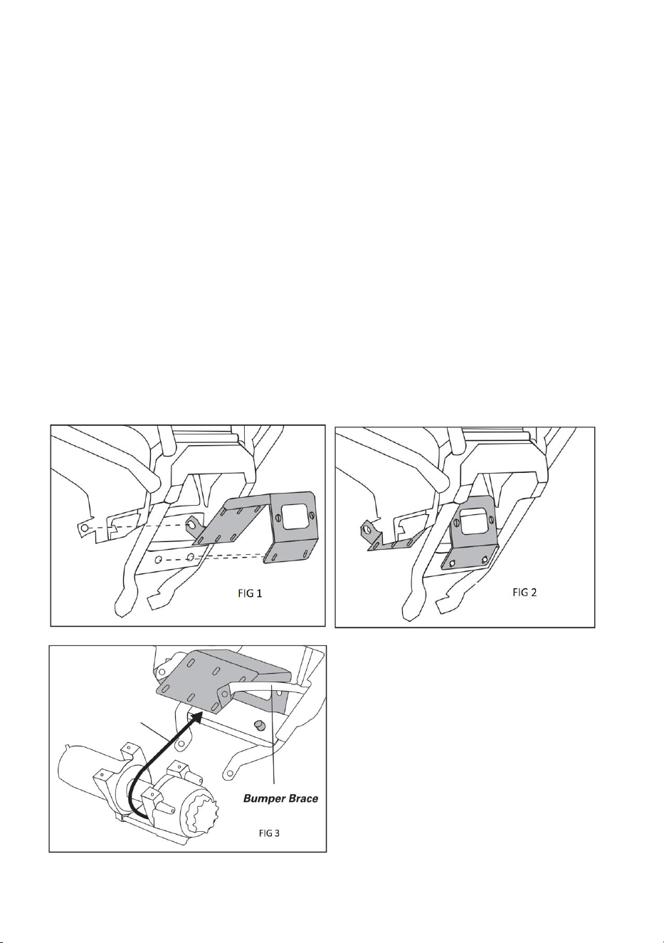
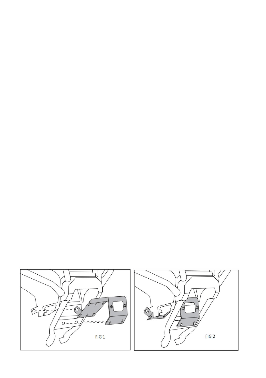
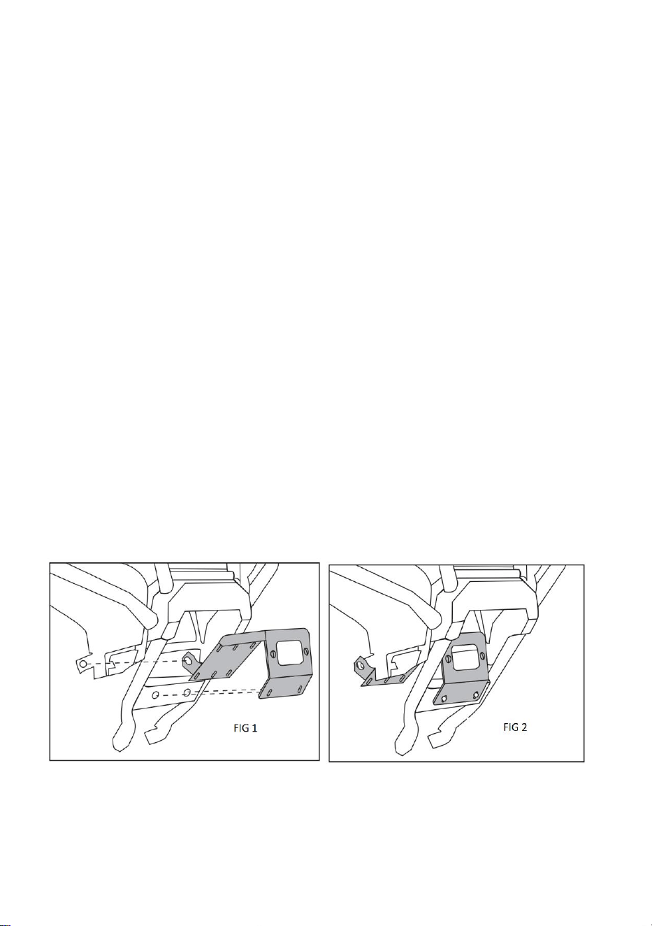
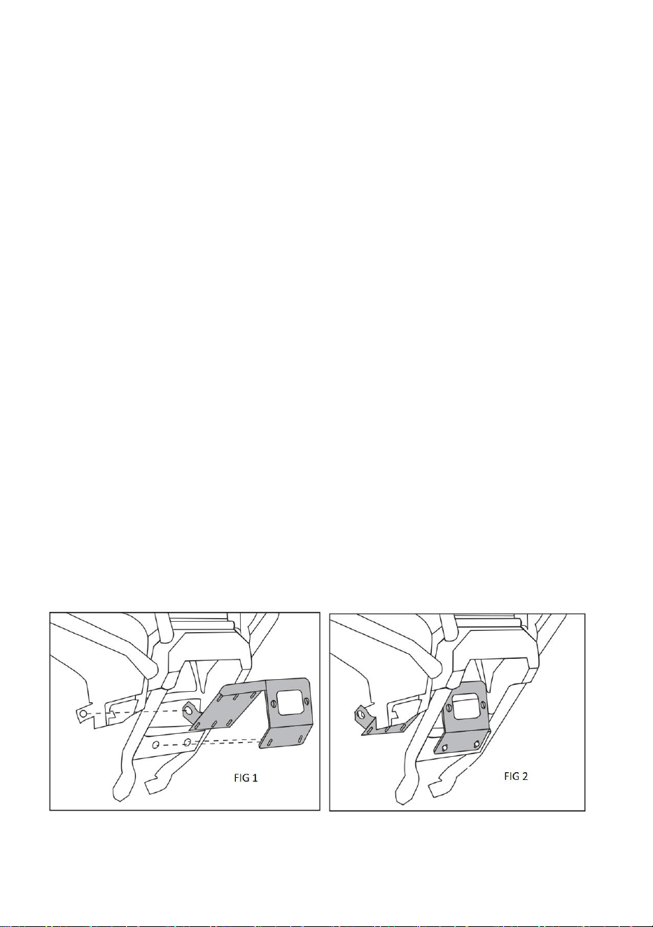
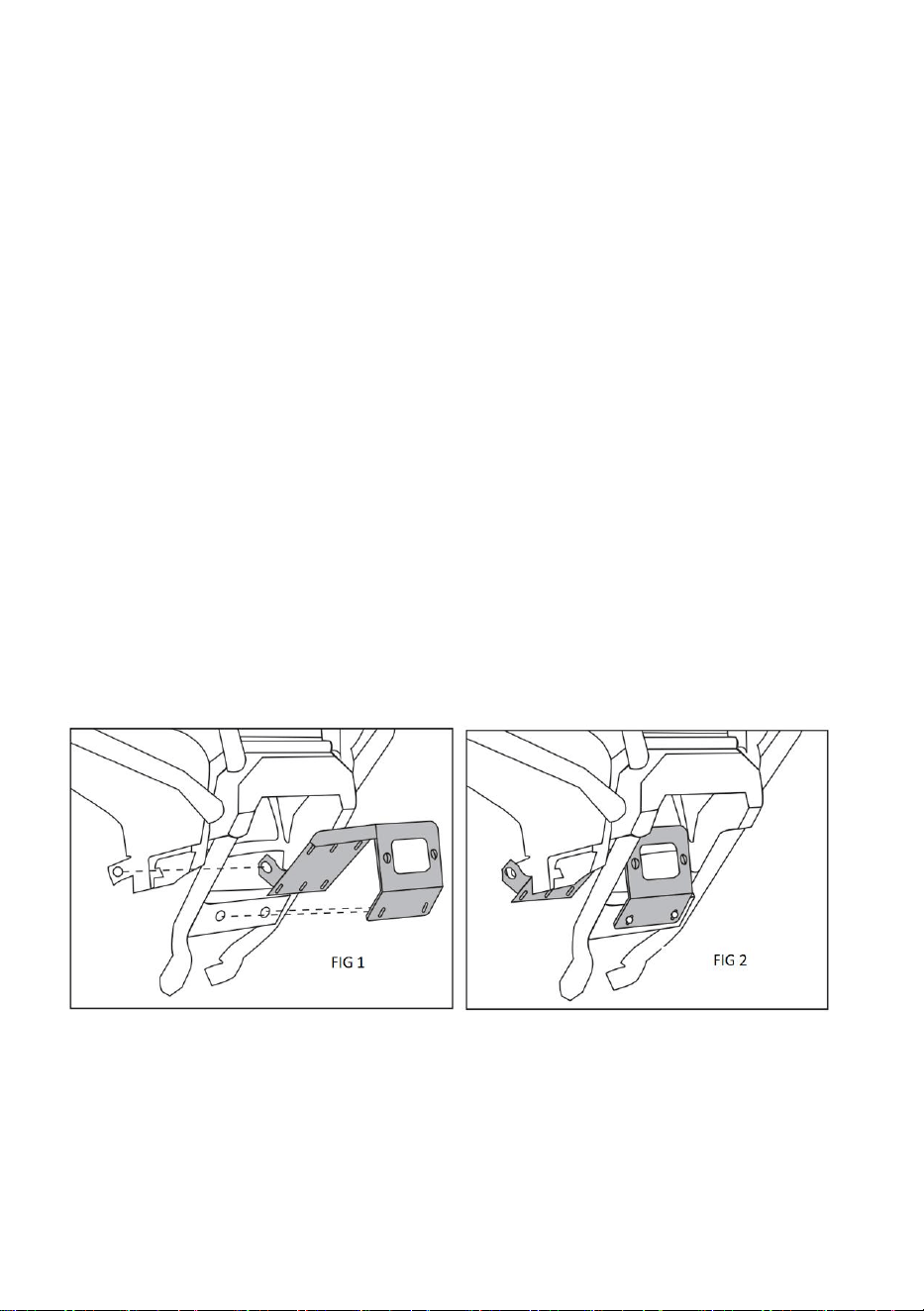
3.Place the winch mounting bracket onto the front bumper, ensuring the
two mounting holes beneath the fairlead cutout on the bracket line up with
the corresponding holes at the bumper’s lower front. Then, align the two
rear winged mounting tabs on the bracket with the bumper’s center frame
attachment holes. (Refer to Fig 1 and 2.)
4.Attach the front of the winch mounting plate to the bumper by inserting a
flanged hex bolt and flanged lock nut through the aligned holes and
tightening them.
Note: Depending on the winch model, the flanged bolts may need to be
installed in reverse, with the lock nut positioned on the outer side of the
assembly.
- 5 -
5.Attach the roller fairlead to the front of the winch mounting bracket using
the included hardware.
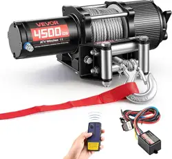
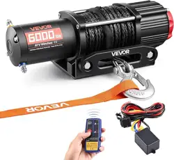
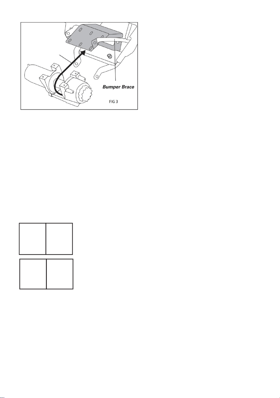
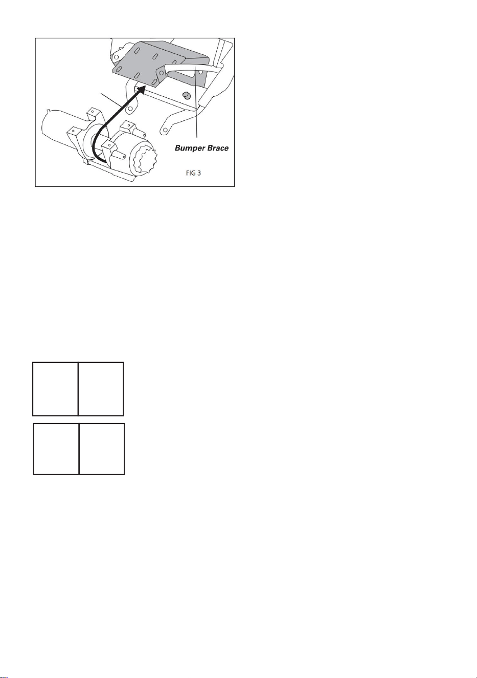
6.Turn the winch so its mounting holes face upward, then slide it into the
bracket from below. Ensure the winch cable feeds out from the bottom (the
side facing the mounting bracket). (Refer to Figure 3.) Line up the
appropriate mounting holes and fasten the winch using the provided
hardware.
7.Reattach the bumper assembly to the ATV frame. Temporarily secure the
top mounting bolts without fully tightening them. Verify that the winged
mounting tabs on the bracket align with the corresponding holes on the
bumper and frame. Use the original bolts to fix the tabs in place.
8.Reinstall the rest of the original hardware to firmly attach the front
bumper to the ATV. Once everything is in position, tighten all fasteners.
9.Follow the winch manufacturer’s wiring guide to correctly connect the
winch to the ATV’s electrical system.
- 6 -
Manufacturer: Shanghaimuxinmuyeyouxiangongsi
Address: Shuangchenglu 803nong11hao1602A-1609shi, baoshanqu,
shanghai 200000 CN.
Imported to AUS: SIHAO PTY LTD. 1 ROKEVA STREETEASTWOOD
NSW 2122 Australia
Imported to USA: Sanven Technology Ltd. Suite 250, 9166 Anaheim
Place, Rancho Cucamonga, CA 91730
REP
UK
YH CONSULTING LIMITED. C/O YH Consulting
Limited Office 147, Centurion House, London
Road, Staines-upon-Thames, Surrey, TW18 4AX
REP
EC
E-CrossStu GmbH
Mainzer Landstr.69,
60329 Frankfurt am Main.

- 7 -
SUPPORT DE TREUIL
MODÈLE : 1910

- 8 -
MODÈLE : 1910
Ceci est le mode d'emploi d'origine. Veuillez lire attentivement l'intégralité
du manuel avant utilisation. VEVOR se réserve le droit d'interpréter
clairement ce manuel d'utilisation. L'apparence du produit dépend du
produit que vous avez reçu. Veuillez nous excuser pour les éventuelles
mises à jour technologiques ou logicielles.
WINCH MOUNT

- 9 -
MESURES DE SÉCURITÉ IMPORTANTES
AVERTISSEMENT : Veuillez lire attentivement et comprendre
l'intégralité de ce manuel avant d'utiliser ou d'entretenir ce
produit. Le non-respect de ces avertissements et instructions
peut entraîner des blessures corporelles ou des dommages matériels.
1. Assemblez uniquement en suivant ces instructions. Un assemblage
incorrect peut entraîner des dangers.
2. Portez des lunettes de sécurité approuvées ANSI et des gants de travail
robustes pendant l'assemblage et l' utilisation.
3. Gardez la zone de montage propre et bien éclairée.
4. Gardez les spectateurs hors de la zone pendant le montage.
5. Ne vous assemblez pas lorsque vous êtes fatigué ou sous l’influence de
l’alcool, de drogues ou de médicaments.
6. Les capacités du produit s'appliquent uniquement au produit
correctement et complètement assemblé.
7. Pour plus d'informations sur les pièces listées dans les pages suivantes,
veuillez vous référer au schéma d'assemblage de ce manuel. Déballez et
séparez toutes les pièces dans un espace de travail propre. Veuillez
conserver les petites pièces hors de portée des enfants.
EMBALLER CONTENU
Partie
Description
Qté
1
SUPPORT DE TREUIL
1
2
Boulon hexagonal à bride M8*20
4
3
écrous M 8
4

- 10 -
AVANT L'INSTALLATION :
1. Éteignez le véhicule et serrez le frein de stationnement.
2. Repérez le compartiment de la batterie. Débranchez les câbles de la
batterie en retirant d'abord la borne négative, puis la borne positive.
INSTRUCTIONS D'INSTALLATION :
1. Pour retirer ou desserrer la plaque de protection du VTT, dévissez les
deux boulons situés en haut de sa paroi latérale.
2. Le pare-chocs est fixé au cadre par huit boulons : deux en haut, deux à
l'intérieur de l'aile, près du bloc optique, et quatre près des supports de
bras de suspension avant (deux de chaque côté). Une fois tous les
boulons retirés, retirez le pare-chocs avant et placez-le dans un espace de
travail propre.
3. Placez le support de montage du treuil sur le pare-chocs avant, en
veillant à ce que les deux trous de fixation situés sous la découpe du
guide-câble du support soient alignés avec les trous correspondants situés
à l'avant inférieur du pare-chocs . Alignez ensuite les deux languettes de
fixation arrière du support avec les trous de fixation du cadre central du
pare-chocs . (Voir figures 1 et 2.)
4.Fixez l'avant de la plaque de montage du treuil au pare-chocs en
insérant un boulon hexagonal à bride et un contre-écrou à bride dans les
trous alignés et en les serrant.
Remarque : selon le modèle de treuil, les boulons à bride peuvent devoir

- 11 -
être installés à l'envers, avec le contre-écrou positionné sur le côté
extérieur de l'assemblage.
5.Fixez le guide-câble à rouleau à l'avant du support de montage du treuil
à l'aide du matériel fourni.
6. Tournez le treuil de manière à ce que ses trous de fixation soient
orientés vers le haut, puis glissez-le dans le support par le bas.
Assurez-vous que le câble du treuil sort par le bas (côté face au support de
fixation). (Voir la figure 3.) Alignez les trous de fixation appropriés et fixez le
treuil à l'aide du matériel fourni.
7. Refixez le pare-chocs au cadre du VTT. Fixez temporairement les
boulons de fixation supérieurs sans les serrer complètement. Vérifiez que
les pattes de fixation du support sont alignées avec les trous
correspondants du pare-chocs et du cadre. Utilisez les boulons d'origine
pour fixer les pattes.
8. Réinstallez le reste du matériel d'origine pour fixer solidement le
pare-chocs avant au VTT. Une fois tout en place, serrez toutes les
fixations.
9. Suivez le guide de câblage du fabricant du treuil pour connecter
correctement le treuil au système électrique du VTT .
- 12 -
Fabricant : Shanghaimuxinmuyeyouxiangongsi
Adresse : Shuangchenglu 803nong11hao1602A-1609shi, baoshanqu,
Shanghai 200 000 CN.
Importé en Australie : SIHAO PTY LTD. 1 ROKEVA STREET, ASTWOOD
NSW 2122 Australie
Importé aux États-Unis : Sanven Technology Ltd. Suite 250, 9166
Anaheim
Lieu, Rancho Cucamonga, CA 91730
REP
UK
YH CONSULTING LIMITED. C/O YH Consulting
Limited Office 147, Centurion House, London
Road, Staines-upon-Thames, Surrey, TW18 4AX
REP
EC
E-CrossStu GmbH
Mainzer Landstr.69,
60329 Frankfurt am Main.

- 13 -

- 14 -
WINDENHALTERUNG
MODELL: 1910

- 15 -
MODELL: 1910
Dies ist die Originalanleitung. Bitte lesen Sie alle Anweisungen sorgfältig
durch, bevor Sie das Gerät in Betrieb nehmen. VEVOR behält sich das
Recht vor , die Bedienungsanleitung klar und deutlich zu interpretieren.
Das Aussehen des Produkts hängt vom gelieferten Produkt ab. Bitte haben
Sie Verständnis dafür, dass wir Sie nicht erneut über Technologie- oder
Software-Updates informieren.
WINCH MOUNT

- 16 -
WICHTIGE SICHERHEITSHINWEISE
WARNUNG: Lesen Sie dieses Handbuch vollständig durch,
bevor Sie dieses Produkt bedienen oder warten. Die
Nichtbeachtung dieser Warnungen und Anweisungen kann zu
Verletzungen oder Sachschäden führen.
1. Führen Sie die Montage ausschließlich gemäß dieser Anleitung durch.
Eine unsachgemäße Montage kann zu Gefahren führen.
2. Tragen Sie während der Montage und Verwendung eine ANSI-geprüfte
Schutzbrille und strapazierfähige Arbeitshandschuhe .
3. Halten Sie den Versammlungsbereich sauber und gut beleuchtet.
4. Halten Sie während der Montage unbeteiligte Personen vom Bereich
fern.
5. Montieren Sie nicht, wenn Sie müde sind oder unter dem Einfluss von
Alkohol, Drogen oder Medikamenten stehen.
6. Die Produktfunktionen gelten nur für ordnungsgemäß und vollständig
montierte Produkte.
7. Weitere Informationen zu den auf den folgenden Seiten aufgeführten
Teilen finden Sie im Montageplan dieser Anleitung. Packen Sie alle Teile an
einem sauberen Arbeitsplatz aus und trennen Sie sie voneinander.
Bewahren Sie kleine Ersatzteile außerhalb der Reichweite von Kindern
auf.
PAKET INHALT
Teil
Beschreibung
MENGE
1
Seilwindenhalterung
1
2
M8*20 Sechskantschraube mit Flansch
4
3
M 8 Muttern
4
- 17 -
VOR DER INSTALLATION:
1. Schalten Sie das Fahrzeug aus und ziehen Sie die Feststellbremse an.
2. Suchen Sie das Batteriefach. Trennen Sie die Batteriekabel, indem Sie
zuerst den Minuspol und dann den Pluspol entfernen.
INSTALLATIONSANWEISUNGEN:
1. Um den Unterfahrschutz des ATVs zu entfernen oder zu lösen, lösen Sie
die beiden Schrauben oben an der Seitenwand.
2. Die Stoßstange ist mit acht Schrauben am Rahmen befestigt: zwei oben,
zwei im Kotflügel in der Nähe des Scheinwerfergehäuses und vier in der
Nähe der vorderen Querlenkerhalterungen (zwei auf jeder Seite). Sobald
alle Schrauben entfernt sind, nehmen Sie die vordere Stoßstange ab und
legen Sie sie an einen sauberen Arbeitsplatz.
3. Setzen Sie die Windenhalterung auf die vordere Stoßstange. Achten Sie
dabei darauf, dass die beiden Befestigungslöcher unter der
Seilführungsöffnung der Halterung mit den entsprechenden Löchern an
der unteren Vorderseite der Stoßstange übereinstimmen . Richten Sie
anschließend die beiden hinteren Befestigungslaschen der Halterung an
den Befestigungslöchern im mittleren Rahmen der Stoßstange aus .
(Siehe Abb. 1 und 2.)
4. Befestigen Sie die Vorderseite der Windenmontageplatte an der
- 18 -
Stoßstange, indem Sie eine Sechskantschraube mit Flansch und eine
Sicherungsmutter mit Flansch durch die ausgerichteten Löcher stecken
und festziehen.
Hinweis: Je nach Windenmodell müssen die Flanschschrauben
möglicherweise umgekehrt eingebaut werden, sodass sich die
Kontermutter an der Außenseite der Baugruppe befindet.
5. Befestigen Sie die Rollenführung mit den mitgelieferten Teilen an der
Vorderseite der Windenhalterung.
6. Drehen Sie die Winde so, dass die Befestigungslöcher nach oben
zeigen, und schieben Sie sie anschließend von unten in die Halterung.
Achten Sie darauf, dass das Windenseil unten (der der Halterung
zugewandten Seite) herauskommt. (Siehe Abbildung 3.) Richten Sie die
entsprechenden Befestigungslöcher aus und befestigen Sie die Winde mit
den mitgelieferten Befestigungselementen.
7. Befestigen Sie die Stoßfängereinheit wieder am ATV-Rahmen. Ziehen
Sie die oberen Befestigungsschrauben provisorisch an, ohne sie
vollständig festzuziehen. Achten Sie darauf, dass die geflügelten
Befestigungslaschen an der Halterung mit den entsprechenden Löchern
an Stoßfänger und Rahmen übereinstimmen. Befestigen Sie die Laschen
mit den Originalschrauben.
8. Bringen Sie die restlichen Originalteile wieder an, um die
Frontstoßstange fest am ATV zu befestigen. Sobald alles an Ort und Stelle
ist, ziehen Sie alle Befestigungselemente fest.
Verdrahtungsanleitung des Windenherstellers, um die Winde richtig an das
elektrische System des ATV anzuschließen .

- 19 -
Hersteller: Shanghaimuxinmuyeyouxiangongsi
Adresse: Shuangchenglu 803nong11hao1602A-1609shi, baoshanqu,
Shanghai 200.000 CN.
Importiert nach AUS: SIHAO PTY LTD. 1 ROKEVA STREETEASTWOOD
NSW 2122 Australien
Importiert in die USA: Sanven Technology Ltd. Suite 250, 9166 Anaheim
Place, Rancho Cucamonga, CA 91730
REP
UK
YH CONSULTING LIMITED. C/O YH Consulting
Limited Office 147, Centurion House, London
Road, Staines-upon-Thames, Surrey, TW18 4AX
REP
EC
E-CrossStu GmbH
Mainzer Landstr.69,
60329 Frankfurt am Main.

- 20 -

- 21 -
SUPPORTO PER VERRICELLO
MODELLO: 1910

- 22 -
MODELLO: 1910
Queste sono le istruzioni originali, si prega di leggere attentamente tutte le
istruzioni del manuale prima di utilizzare il prodotto. VEVOR si riserva la
piena interpretazione del manuale utente. L'aspetto del prodotto dipenderà
dal prodotto ricevuto. Vi preghiamo di non informarvi ulteriormente in caso
di aggiornamenti tecnologici o software relativi al nostro prodotto.
WINCH MOUNT

- 23 -
IMPORTANTI MISURE DI SICUREZZA
AVVERTENZA: Leggere attentamente e comprendere l'intero
manuale prima di utilizzare o effettuare la manutenzione del
prodotto. La mancata osservanza di queste avvertenze e
istruzioni può causare lesioni personali o danni a beni di valore.
1. Eseguire il montaggio solo seguendo queste istruzioni. Un montaggio
improprio può comportare pericoli.
2. Indossare occhiali di sicurezza omologati ANSI e guanti da lavoro
resistenti durante il montaggio e l'uso .
3. Mantenere l'area di assemblaggio pulita e ben illuminata.
4. Tenere gli astanti fuori dall'area durante l'assemblea.
5. Non riunirsi quando si è stanchi o sotto l'effetto di alcol, droghe o
farmaci.
6. Le capacità del prodotto si applicano solo al prodotto correttamente e
completamente assemblato.
7. Per ulteriori informazioni sui componenti elencati nelle pagine seguenti,
fare riferimento allo schema di montaggio di questo manuale. Disimballare
e separare tutti i componenti in un'area di lavoro pulita. Tenere i piccoli
pezzi di ricambio fuori dalla portata dei bambini.
PACCHETTO CONTENUTO
Parte
Descrizione
QUANTITÀ
1
SUPPORTO PER VERRICELLO
1
2
Bullone esagonale flangiato M8*20
4
3
M 8
4
- 24 -
PRIMA DELL'INSTALLAZIONE:
1. Spegnere il veicolo e inserire il freno di stazionamento.
2. Individuare il vano batteria. Scollegare i cavi della batteria rimuovendo
prima il terminale negativo, seguito da quello positivo.
ISTRUZIONI PER L'INSTALLAZIONE:
1. Per rimuovere o allentare la piastra paramotore dell'ATV, svitare i due
bulloni situati nella parte superiore della parete laterale.
2. Il paraurti è fissato al telaio con 8 bulloni: due nella parte superiore, due
all'interno del parafango, vicino al faro anteriore, e quattro vicino ai supporti
del braccio della sospensione anteriore (due per lato). Una volta rimossi
tutti i bulloni, smontare il paraurti anteriore e posizionarlo in un'area di
lavoro pulita.
3. Posizionare la staffa di montaggio del verricello sul paraurti anteriore,
assicurandosi che i due fori di montaggio sotto il foro passacavo sulla
staffa siano allineati con i fori corrispondenti nella parte anteriore inferiore
del paraurti . Quindi, allineare le due linguette di montaggio posteriori con
alette sulla staffa con i fori di fissaggio del telaio centrale del paraurti . (Vedi
Fig. 1 e 2.)
4. Fissare la parte anteriore della piastra di montaggio del verricello al
paraurti inserendo un bullone esagonale flangiato e un dado di bloccaggio
flangiato attraverso i fori allineati e serrandoli.
Nota: a seconda del modello di verricello, potrebbe essere necessario

- 25 -
installare i bulloni flangiati al contrario, con il dado di bloccaggio
posizionato sul lato esterno del gruppo.
5. Fissare il passacavo a rulli alla parte anteriore della staffa di montaggio
del verricello utilizzando la ferramenta in dotazione.
6. Ruotare il verricello in modo che i fori di montaggio siano rivolti verso
l'alto, quindi inserirlo nella staffa dal basso. Assicurarsi che il cavo del
verricello esca dal basso (il lato rivolto verso la staffa di montaggio). (Fare
riferimento alla Figura 3.) Allineare i fori di montaggio appropriati e fissare il
verricello utilizzando la ferramenta fornita.
7. Rimontare il paraurti al telaio dell'ATV. Fissare temporaneamente i
bulloni di montaggio superiori senza stringerli completamente. Verificare
che le linguette di montaggio ad alette sulla staffa siano allineate con i fori
corrispondenti sul paraurti e sul telaio. Utilizzare i bulloni originali per
fissare le linguette in posizione.
8. Reinstallare il resto della bulloneria originale per fissare saldamente il
paraurti anteriore al quad. Una volta che tutto è in posizione, stringere tutti i
dispositivi di fissaggio.
9. Seguire la guida al cablaggio del produttore del verricello per collegare
correttamente il verricello all'impianto elettrico dell'ATV .
- 26 -
Produttore: Shanghaimuxinmuyeyouxiangongsi
Indirizzo: Shuangchenglu 803nong11hao1602A-1609shi, baoshanqu,
shanghai 200000 CN.
Importato in AUS: SIHAO PTY LTD. 1 ROKEVA STREETEASTWOOD
Nuovo Galles del Sud 2122 Australia
Importato negli USA: Sanven Technology Ltd. Suite 250, 9166 Anaheim
Luogo, Rancho Cucamonga, CA 91730
REP
UK
YH CONSULTING LIMITED. C/O YH Consulting
Limited Office 147, Centurion House, London
Road, Staines-upon-Thames, Surrey, TW18 4AX
REP
EC
E-CrossStu GmbH
Mainzer Landstr.69,
60329 Frankfurt am Main.

- 27 -

- 28 -
MONTAJE DEL CABRESTANTE
MODELO: 1910

- 29 -
MODELO: 1910
Estas son las instrucciones originales; lea atentamente todas las
instrucciones del manual antes de utilizarlo. VEVOR se reserva el derecho
de interpretar su manual de usuario. La apariencia del producto dependerá
del producto que haya recibido. Le rogamos que nos disculpe si no le
informamos de nuevo si hay actualizaciones tecnológicas o de software en
nuestro producto.
WINCH MOUNT

- 30 -
MEDIDAS DE SEGURIDAD IMPORTANTES
ADVERTENCIA: Lea y comprenda completamente este manual
antes de operar o realizar tareas de mantenimiento en este
producto. El incumplimiento de estas advertencias e
instrucciones puede causar lesiones personales o daños a bienes
valiosos.
1. Ensamble únicamente según estas instrucciones. Un montaje incorrecto
puede causar peligros.
2. Use gafas de seguridad aprobadas por ANSI y guantes de trabajo
resistentes durante el montaje y el uso.
3. Mantenga el área de montaje limpia y bien iluminada.
4. Mantenga a los transeúntes fuera del área durante el montaje.
5. No realice el montaje cuando esté cansado o bajo la influencia de
alcohol, drogas o medicamentos.
6. Las capacidades del producto se aplican únicamente a productos
ensamblados de manera correcta y completa.
7. Para obtener más información sobre las piezas que se listan en las
páginas siguientes, consulte el diagrama de montaje de este manual.
Desembale y separe todas las piezas en un área de trabajo limpia.
Mantenga las piezas de repuesto pequeñas fuera del alcance de los niños.
PAQUETE CONTENIDO
Parte
Descripción
CANTIDAD
1
SOPORTE DE CABRESTANTE
1
2
Perno hexagonal con brida M8*20
4
3
M 8
4
- 31 -
ANTES DE LA INSTALACIÓN:
1. Apague el vehículo y accione el freno de estacionamiento.
2. Localice el compartimento de la batería. Desconecte los cables de la
batería quitando primero el terminal negativo y luego el positivo.
INSTRUCCIONES DE INSTALACIÓN:
1. Para quitar o aflojar la placa protectora del ATV, afloje los dos pernos
ubicados en la parte superior de su pared lateral.
2. El parachoques se fija al chasis con 8 pernos: dos en la parte superior,
dos dentro del guardabarros, cerca del faro, y cuatro cerca de los soportes
del brazo de la suspensión delantera (dos a cada lado). Una vez retirados
todos los pernos, retire el parachoques delantero y colóquelo en un área
de trabajo limpia.
3. Coloque el soporte de montaje del cabrestante en el parachoques
delantero, asegurándose de que los dos orificios de montaje debajo del
recorte del guíacabos del soporte coincidan con los orificios
correspondientes en la parte frontal inferior del parachoques . A
continuación, alinee las dos pestañas de montaje traseras del soporte con
los orificios de fijación del marco central del parachoques . (Consulte las
figuras 1 y 2).
4. Fije la parte delantera de la placa de montaje del cabrestante al
parachoques insertando un perno hexagonal con brida y una tuerca de
- 32 -
seguridad con brida a través de los orificios alineados y apretándolos.
Nota: Dependiendo del modelo del cabrestante, es posible que sea
necesario instalar los pernos con brida en sentido inverso, con la tuerca de
seguridad colocada en el lado exterior del conjunto.
5. Fije el rodillo guía a la parte delantera del soporte de montaje del
cabrestante usando los herrajes incluidos.
6. Gire el cabrestante de modo que los orificios de montaje queden hacia
arriba y deslícelo en el soporte desde abajo. Asegúrese de que el cable del
cabrestante salga por la parte inferior (el lado que mira hacia el soporte de
montaje). (Consulte la Figura 3). Alinee los orificios de montaje
correspondientes y fije el cabrestante con los herrajes incluidos.
7. Vuelva a colocar el parachoques en el chasis del ATV. Fije
temporalmente los pernos de montaje superiores sin apretarlos
completamente. Verifique que las pestañas de montaje del soporte estén
alineadas con los orificios correspondientes en el parachoques y el chasis.
Utilice los pernos originales para fijar las pestañas.
8. Vuelva a instalar el resto de los herrajes originales para fijar firmemente
el parachoques delantero al ATV. Una vez que todo esté en su lugar,
apriete todos los sujetadores.
9. Siga la guía de cableado del fabricante del cabrestante para conectar
correctamente el cabrestante al sistema eléctrico del ATV .

- 33 -
Fabricante: Shanghaimuxinmuyeyouxiangongsi
Dirección: Shuangchenglu 803nong11hao1602A-1609shi, baoshanqu,
Shanghái 200000 CN.
Importado a AUS: SIHAO PTY LTD. 1 ROKEVA STREET, EASTWOOD
NSW 2122 Australia
Importado a EE. UU.: Sanven Technology Ltd. Suite 250, 9166 Anaheim
Lugar, Rancho Cucamonga, CA 91730
REP
UK
YH CONSULTING LIMITED. C/O YH Consulting
Limited Office 147, Centurion House, London
Road, Staines-upon-Thames, Surrey, TW18 4AX
REP
EC
E-CrossStu GmbH
Mainzer Landstr.69,
60329 Frankfurt am Main.

- 34 -

- 35 -
MOCOWANIE WYCIĄGARKI
MODEL: 1910

- 36 -
MODEL: 1910
To jest oryginalna instrukcja, przed użyciem należy uważnie przeczytać
wszystkie instrukcje. VEVOR zastrzega sobie jasną interpretację naszej
instrukcji obsługi. Wygląd produktu będzie zależał od produktu, który
otrzymałeś. Prosimy o wybaczenie, że nie poinformujemy Cię ponownie,
jeśli w naszym produkcie pojawią się jakiekolwiek aktualizacje
technologiczne lub oprogramowania.
WINCH MOUNT

- 37 -
WAŻNE ZABEZPIECZENIA
OSTRZEŻENIE: Przed rozpoczęciem obsługi lub serwisowania
tego produktu należy przeczytać i zrozumieć całą instrukcję.
Nieprzestrzeganie tych ostrzeżeń i instrukcji może spowodować
obrażenia ciała lub uszkodzenie cennego mienia.
1. Montaż należy wykonywać wyłącznie zgodnie z niniejszą instrukcją.
Nieprawidłowy montaż może stwarzać zagrożenia.
2. Podczas montażu i użytkowania należy nosić okulary ochronne
zatwierdzone przez ANSI oraz wytrzymałe rękawice robocze .
3. Utrzymuj miejsce zgromadzenia w czystości i zapewnij dobre
oświetlenie.
4. Podczas montażu nie dopuszczaj osób postronnych na teren montażu.
5. Nie przychodź na spotkania, jeśli jesteś zmęczony lub pod wpływem
alkoholu, narkotyków lub leków.
6. Możliwości produktu odnoszą się wyłącznie do produktu prawidłowo i
kompletnie zmontowanego.
7. Aby uzyskać dodatkowe informacje dotyczące części wymienionych na
kolejnych stronach, zapoznaj się ze schematem montażu w niniejszej
instrukcji. Rozpakuj i rozdziel wszystkie części w czystym miejscu pracy.
Trzymaj małe części zamienne poza zasięgiem dzieci.
PAKIET ZAWARTOŚĆ
Część
Opis
ILOŚĆ
1
MOCOWANIE WYCIĄGARKI
1
2
Śruba sześciokątna kołnierzowa M8*20
4
3
Nakrętki M 8
4

- 38 -
PRZED INSTALACJĄ:
1. Wyłącz pojazd i zaciągnij hamulec postojowy.
2. Znajdź komorę baterii. Odłącz kable baterii, najpierw usuwając zacisk
ujemny, a następnie zacisk dodatni.
INSTRUKCJE INSTALACJI:
1. Aby zdjąć lub poluzować płytę osłonową pojazdu ATV, odkręć dwie
śruby znajdujące się u góry jego ściany bocznej.
2. Zderzak jest przymocowany do ramy za pomocą 8 śrub: dwie na górze,
dwie wewnątrz błotnika blisko osłony reflektora i cztery blisko mocowań
przedniego wahacza (dwie po każdej stronie). Po wykręceniu wszystkich
śrub zdejmij przedni zderzak i umieść go w czystym miejscu roboczym.
3. Umieść wspornik montażowy wyciągarki na przednim zderzaku,
upewniając się, że dwa otwory montażowe pod wycięciem prowadnicy na
wsporniku pokrywają się z odpowiednimi otworami w dolnej przedniej
części zderzaka . Następnie wyrównaj dwa tylne skrzydełkowe zaczepy
montażowe na wsporniku z otworami montażowymi środkowej ramy
zderzaka . (Patrz rys. 1 i 2.)
4. Przymocuj przód płyty montażowej wyciągarki do zderzaka, wkładając
śrubę sześciokątną z kołnierzem i nakrętkę zabezpieczającą z kołnierzem
przez wyrównane otwory i dokręcając je.
- 39 -
Uwaga: W zależności od modelu wyciągarki może być konieczne
zamontowanie śrub kołnierzowych w odwrotnej kolejności, przy czym
nakrętka zabezpieczająca powinna znajdować się po zewnętrznej stronie
zespołu.
5. Za pomocą dołączonych elementów montażowych przymocuj
prowadnicę rolkową do przedniej części uchwytu montażowego
wyciągarki.
6. Obróć wyciągarkę tak, aby jej otwory montażowe były skierowane do
góry, a następnie wsu ń ją do wspornika od dołu. Upewnij się, że lina
wyciągarki wychodzi od dołu (strona skierowana w stronę wspornika
montażowego). (Patrz Rysunek 3.) Wyrównaj odpowiednie otwory
montażowe i zamocuj wyciągarkę za pomocą dostarczonego sprzętu.
7. Ponownie przymocuj zderzak do ramy ATV. Tymczasowo przymocuj
górne śruby mocujące, nie dokręcając ich całkowicie. Sprawdź, czy
skrzydełkowe zaczepy mocujące na uchwycie są wyrównane z
odpowiednimi otworami w zderzaku i ramie. Użyj oryginalnych śrub, aby
zamocować zaczepy na miejscu.
8. Ponownie zainstaluj resztę oryginalnego sprzętu, aby solidnie
przymocować przedni zderzak do ATV. Gdy wszystko będzie na swoim
miejscu, dokręć wszystkie elementy mocujące.
producenta wyciągarki , aby prawidłowo podłączyć wyciągarkę do układu
elektrycznego pojazdu ATV .

- 40 -
Producent: Shanghaimuxinmuyeyouxiangongsi
Adres: Shuangchenglu 803nong11hao1602A-1609shi, baoshanqu,
Szanghaj 200000 CN.
Importowane do AUS: SIHAO PTY LTD. 1 ROKEVA
STREETEASTWOOD
NSW 2122 Australia
Importowane do USA: Sanven Technology Ltd. Suite 250, 9166 Anaheim
Miejsce, Rancho Cucamonga, CA 91730
REP
UK
YH CONSULTING LIMITED. C/O YH Consulting
Limited Office 147, Centurion House, London
Road, Staines-upon-Thames, Surrey, TW18 4AX
REP
EC
E-CrossStu GmbH
Mainzer Landstr.69,
60329 Frankfurt am Main.

- 41 -

- 42 -
LIERBEVESTIGING
MODEL: 1910

- 43 -
MODEL: 1910
Dit is de originele handleiding. Lees alle instructies zorgvuldig door voordat
u het product gebruikt. VEVOR behoudt zich het recht voor om de
gebruiksaanwijzing duidelijk te interpreteren. Het uiterlijk van het product is
afhankelijk van het product dat u hebt ontvangen. Neemt u het ons niet
kwalijk dat we u niet meer op de hoogte stellen van eventuele
technologische of software-updates voor ons product.
WINCH MOUNT

- 44 -
BELANGRIJKE VEILIGHEIDSMAATREGELEN
WAARSCHUWING: Lees deze volledige handleiding zorgvuldig
door voordat u dit product bedient of onderhoudt. Het niet
opvolgen van deze waarschuwingen en instructies kan leiden tot
persoonlijk letsel of schade aan waardevolle eigendommen.
1. Monteer uitsluitend volgens deze instructies. Onjuiste montage kan
gevaarlijk zijn.
2. Draag een ANSI-goedgekeurde veiligheidsbril en stevige
werkhandschoenen tijdens montage en gebruik .
3. Zorg ervoor dat de verzamelplaats schoon en goed verlicht is.
4. Houd omstanders uit de buurt tijdens de montage.
5. Kom niet in actie als u moe bent of onder invloed van alcohol, drugs of
medicijnen.
6. De producteigenschappen gelden uitsluitend voor producten die correct
en volledig zijn gemonteerd.
7. Raadpleeg voor meer informatie over de onderdelen die op de volgende
pagina's worden vermeld, het montageschema in deze handleiding. Pak
alle onderdelen uit en scheid ze van elkaar op een schone werkplek. Houd
kleine reserveonderdelen buiten bereik van kinderen.
PAKKET INHOUD
Deel
Beschrijving
AANTAL
1
Lierbevestiging
1
2
M8*20 geflensde zeskantbout
4
3
M 8 moeren
4
- 45 -
VOOR INSTALLATIE:
1. Schakel het voertuig uit en trek de parkeerrem aan.
2. Zoek het batterijcompartiment. Ontkoppel de batterijkabels door eerst de
negatieve pool te verwijderen en vervolgens de positieve pool.
INSTALLATIE-INSTRUCTIES:
1. Om de skidplate van de ATV te verwijderen of los te maken, draait u de
twee bouten aan de bovenkant van de zijwand los.
2. De bumper wordt met 8 bouten aan het frame bevestigd: twee aan de
bovenkant, twee aan de binnenkant van het spatbord, vlakbij de
koplampbehuizing, en vier bij de bevestigingspunten van de voorste
draagarm (twee aan elke kant). Zodra alle bouten zijn verwijderd,
demonteert u de voorbumper en legt u deze op een schone werkplek.
3. Plaats de liermontagebeugel op de voorbumper en zorg ervoor dat de
twee montagegaten onder de kabelgeleideruitsparing op de beugel
uitgelijnd zijn met de corresponderende gaten aan de onderzijde van de
bumper . Lijn vervolgens de twee bevestigingslipjes van de achtervleugel
op de beugel uit met de bevestigingsgaten van het middelste frame van de
bumper . (Zie figuur 1 en 2.)
4. Bevestig de voorzijde van de liermontageplaat aan de bumper door een
zeskantbout met flens en een borgmoer met flens door de uitgelijnde gaten
te steken en deze vast te draaien.
Let op: Afhankelijk van het liermodel moeten de flensbouten mogelijk
- 46 -
omgekeerd worden gemonteerd, waarbij de borgmoer aan de buitenkant
van de constructie zit.
5. Bevestig de rolgeleider aan de voorkant van de liermontagebeugel met
behulp van de meegeleverde hardware.
6. Draai de lier zo dat de montagegaten naar boven wijzen en schuif hem
vervolgens van onderaf in de beugel. Zorg ervoor dat de lierkabel aan de
onderkant naar buiten loopt (de kant die naar de montagebeugel wijst).
(Zie afbeelding 3.) Lijn de juiste montagegaten uit en bevestig de lier met
het meegeleverde bevestigingsmateriaal.
7. Bevestig de bumperconstructie weer aan het ATV-frame. Draai de
bovenste bevestigingsbouten tijdelijk vast, maar draai ze niet helemaal
vast. Controleer of de gevleugelde bevestigingslipjes op de beugel
uitgelijnd zijn met de corresponderende gaten in de bumper en het frame.
Gebruik de originele bouten om de lipjes vast te zetten.
8. Plaats de rest van de originele bevestigingsmaterialen terug om de
voorbumper stevig aan de ATV te bevestigen. Zodra alles op zijn plaats zit,
draait u alle bevestigingsmiddelen vast.
9. Volg de bedradingshandleiding van de fabrikant van de lier om de lier
correct aan te sluiten op het elektrische systeem van de ATV.

- 47 -
Fabrikant: Shanghaimuxinmuyeyouxiangongsi
Adres: Shuangchenglu 803nong11hao1602A-1609shi, baoshanqu,
shanghai 200000 CN.
Geïmporteerd naar AUS: SIHAO PTY LTD. 1 ROKEVA
STREETEASTWOOD
NSW 2122 Australië
Geïmporteerd naar de VS: Sanven Technology Ltd. Suite 250, 9166
Anaheim
Plaats, Rancho Cucamonga, CA 91730
REP
UK
YH CONSULTING LIMITED. C/O YH Consulting
Limited Office 147, Centurion House, London
Road, Staines-upon-Thames, Surrey, TW18 4AX
REP
EC
E-CrossStu GmbH
Mainzer Landstr.69,
60329 Frankfurt am Main.

- 48 -

- 49 -
VINSCHFÄSTE
MODELL: 1910

- 50 -
MODELL: 1910
Detta är originalinstruktionerna, vänligen läs alla instruktioner noggrant
innan du använder produkten. VEVOR förbehåller sig en tydlig tolkning av
vår användarmanual. Produktens utseende ska vara beroende av den
produkt du mottagit. Vi ber om ursäkt för att vi inte kommer att informera
dig igen om det finns några teknik- eller programuppdateringar för vår
produkt.
WINCH MOUNT

- 51 -
VIKTIGA SÄKERHETSÅTGÄRDER
VARNING: Läs och förstå hela denna manual innan du
använder eller utför service på denna produkt. Underlåtenhet att
följa dessa varningar och instruktioner kan orsaka personskador
eller skador på värdefull egendom.
1. Montera endast enligt dessa instruktioner. Felaktig montering kan skapa
risker.
2. Använd ANSI-godkända skyddsglasögon och kraftiga arbetshandskar
under montering och användning .
3. Håll samlingsområdet rent och väl upplyst.
4. Håll åskådare borta från området under monteringen.
5. Montera inte när du är trött eller påverkad av alkohol, droger eller
mediciner.
6. Produktegenskaperna gäller endast korrekt och fullständigt monterade
produkter.
7. För ytterligare information om delarna som listas på följande sidor, se
monteringsschemat i denna manual. Packa upp och separera alla delar på
en ren arbetsyta. Förvara små reservdelar utom räckhåll för barn.
PAKET INNEHÅLL
Del
Beskrivning
ANTAL
1
VINSCHFÄSTE
1
2
M8*20 flänsad sexkantsbult
4
3
M 8 muttrar
4

- 52 -
FÖRE INSTALLATION:
1. Stäng av fordonet och dra åt parkeringsbromsen.
2. Hitta batterifacket. Koppla bort batterikablarna genom att först ta bort
den negativa polen och sedan den positiva polen.
INSTALLATIONSANVISNINGAR:
1. För att ta bort eller lossa ATV:ns hasplåt, lossa de två bultarna som sitter
högst upp på sidoväggen.
2. Stötfångaren är fäst vid ramen med 8 bultar: två högst upp, två inuti
skärmen nära strålkastarhuset och fyra nära de främre bärarmens fästen
(två på varje sida). När alla bultar är borttagna, ta bort den främre
stötfångaren och placera den på en ren arbetsyta.
3. Placera vinschens monteringsfäste på den främre stötfångaren och se
till att de två monteringshålen under kåpans urskärning på fästet är i linje
med motsvarande hål längst ner på stötfångaren . Rikta sedan in de två
bakre vingformade monteringsflikarna på fästet med stötfångarens
mittramsfästhål . (Se figur 1 och 2.)
4. Fäst vinschens monteringsplattas framsida på stötfångaren genom att
sätta i en flänsad sexkantsbult och en flänsad låsmutter genom de
inriktade hålen och dra åt dem.
Obs: Beroende på vinschmodell kan flänsbultarna behöva monteras i
omvänd ordning, med låsmuttern placerad på utsidan av enheten.
5. Fäst rullledningen på framsidan av vinschens monteringsfäste med den

- 53 -
medföljande hårdvaran.
6. Vrid vinschen så att monteringshålen är vända uppåt och skjut sedan in
den i fästet underifrån. Se till att vinschvajern matas ut från botten (sidan
som är vänd mot monteringsfästet). (Se figur 3.) Rikta in lämpliga
monteringshål och fäst vinschen med de medföljande beslagen .
7. Sätt tillbaka stötfångarenheten på fyrhjulingens ram. Fäst tillfälligt de
övre monteringsbultarna utan att dra åt dem helt. Kontrollera att de
vingformade monteringsflikarna på fästet är i linje med motsvarande hål på
stötfångaren och ramen. Använd originalbultarna för att fästa flikarna på
plats.
8. Sätt tillbaka resten av originalbeslagen för att fästa den främre
stötfångaren ordentligt på fyrhjulingen. När allt är på plats, dra åt alla
fästelement.
Följ vinschtillverkarens kopplingsanvisning för att ansluta vinschen korrekt
till fyrhjulingens elsystem .

- 54 -
Tillverkare: Shanghaimuxinmuyeyouxiangongsi
Adress: Shuangchenglu 803nong11hao1602A-1609shi, baoshanqu,
Shanghai 200 000 kanadensiska republiken.
Importerad till Australien: SIHAO PTY LTD. 1 ROKEVA
STREETEASTWOOD
NSW 2122 Australien
Importerad till USA: Sanven Technology Ltd. Suite 250, 9166 Anaheim
Plats, Rancho Cucamonga, Kalifornien 91730
REP
UK
YH CONSULTING LIMITED. C/O YH Consulting
Limited Office 147, Centurion House, London
Road, Staines-upon-Thames, Surrey, TW18 4AX
REP
EC
E-CrossStu GmbH
Mainzer Landstr.69,
60329 Frankfurt am Main.

- 55 -