GV-AS1620 Controller
Before attempting to connect or operate this product, please
read these instructions carefully and save this manual for future use.
User’s Manual
AS1620V203-A

© 2024 GeoVision, Inc. All rights reserved.
Under the copyright laws, this manual may not be copied,
in whole or in part,
without the written consent of GeoVision.
Every effort has been made to ensure that the information in this manual is
accurate. GeoVision, Inc. makes no expressed or implied warranty of any kind
and assumes no responsibility for errors or omissions. No liability is assumed
for incidental or consequential damages arising from the use of the information
or products contained herein. Features and specifications are subject to
change without notice.
GeoVision, Inc.
9F, No. 246, Sec. 1, Neihu Rd.,
Neihu District, Taipei, Taiwan
Tel: +886-2-8797-8377
Fax: +886-2-8797-8335
http://www.geovision.com.tw
Trademarks used in this manual: GeoVision, the GeoVision logo and GV
series products are trademarks of GeoVision, Inc. Windows is the registered
trademark of Microsoft Corporation.
December 2024
Scan the following QR codes for product warranty and technical support
policy:
[Warranty] [Technical Support Policy]

i
Contents
Optional Devices ....................................................................................................... i
Chapter 1 Introduction ............................................................................................. 1
1.1 Key Features.................................................................................................... 1
1.2 Firmware and GV-ASManager Compatibility .................................................... 2
1.3 Packing List ..................................................................................................... 2
1.4 Overview .......................................................................................................... 3
Chapter 2 Installing on a Network ........................................................................... 3
2.1 Checking the Dynamic IP Address ................................................................... 4
2.2 Configuring the Static IP Address ..................................................................... 5
2.3 Configuring DDNS Connection ......................................................................... 5
Chapter 3 The Web Interface for GV-ASManager Connection ........................... 11
3.1 Basic Settings .........................................................................................................12
3.1.1 System Setup ...............................................................................................12
3.1.2 Firmware Update..........................................................................................11
3.1.3 Security Configuration ..................................................................................12
3.2 Advanced Settings ..................................................................................................12
3.2.1 Function Configuration .................................................................................13
3.2.2 Parameter Configuration ..............................................................................16
3.2.3 Time Configuration .......................................................................................18
3.2.4 Input Configuration .......................................................................................19
3.2.5 Output Configuration ....................................................................................19
3.2.6 Log Viewer ...................................................................................................20
3.2.7 System Log Viewer ......................................................................................20
3.3 Extended Device .....................................................................................................21
Chapter 4 The Web Interface for GV-Cloud Access Control Connection ......... 25
4.1 Basic Settings .........................................................................................................26
4.1.1 System Setup ...............................................................................................26
4.1.2 Firmware Update..........................................................................................28
4.1.3 Security Configuration ..................................................................................29
4.2 Advanced Settings ..................................................................................................31
4.2.1 Function Configuration .................................................................................32
4.2.2 Parameter Configuration ..............................................................................33
4.2.3 Card Configuration .......................................................................................35
4.2.4 Time Configuration .......................................................................................36
4.2.5 Input Configuration .......................................................................................36
4.2.6 Output Configuration ....................................................................................36

ii
4.2.7 System Log Viewer ......................................................................................36
4.3 Extended Device .....................................................................................................37
4.3.1 Extended Reader Configuration ...................................................................37
4.3.2 Extended Camera Configuration ..................................................................39
4.3.2.1 Connecting GV-Cloud Bridge to GV-AS1620 ........................................39
4.3.2.2 Connecting IP Cameras to GV-AS1620 ................................................41
Chapter 5 Troubleshooting ................................................................................... 44
iii
Optional Devices
Optional devices can expand the capabilities and versatilities of your controller. Consult our
sales representative for more information.
GV-AS ID Card / Key Fob &
GV-UHF Tag
GV-AS ID Card and GV-AS ID Key Fob are ideal for business and
residential environment, where access control is important for security
reasons. 125 KHz and 13.56 MHz cards and key fobs are available.
GV-UHF Tag is ideal for parking lot management. 900 MHz UHF Tag
is available.
GV-FWC
GV-FWC can integrate GV-Face Recognition Cameras (GV-FD8700-
FR / GV-VD8700) into access control systems by sending access card
data, paired to Face IDs, to controllers either through TCP/IP or
Wiegand connection.
GV-IB25 / 65 / 85 Infrared
Button
The GV‐IB25 / 65 / 85 Infrared Button detects infrared movement
within 3 to 12 cm and allows you to open the door with a wave of
hand.
GV-POE Switch
The GV‐POE Switch is designed to provide power along with network
connection for IP devices. The GV‐POE Switch is available in various
models with different numbers and types of ports.
GV-WTR
GV-WTR is a converter designed to support Wiegand interface to RS-
485 interface, thereby enabling 3
rd
party readers to be connected to
RS-485 GV-Controllers. Through the GV-WTR, Wiegand-interface
readers can be easily combined to access control systems for
improved versatility.
Electric Lock
Three types of electric locks are available: electromagnetic lock,
electric bolt and electric strike.
Power Adapter
Contact our sales representatives for the countries and areas
supported.
Push Button Switch
The push button switch can be integrated with access control system,
allowing door exit by momentarily activating or deactivating the electric
locking device. Both American standard and European standard push
buttons are available.

Introduction
1
1
Chapter 1 Introduction
GV-AS1620 is a single door controller with three types of interfaces, Wiegand, RS-485 and
TCP/IP, to accommodate various readers for entry and exit management. Through its I/O
pins, it provides not only basic door operations but also alarm, tamper and fire senor
applications, as well as allowing LEDs connected to indicate an access granted and denied.
When directly connecting to IP cameras or connecting IP cameras using the GV-Cloud
Bridge encoder, GV-AS1620 (firmware V2.00 or later) can transmit the snapshots, live view,
and playback recordings to GV-Cloud Access Control upon access events.
1.1 Key Features
• One door IP controller (entry and exit)
• 3 types of interfaces, Wiegand, RS-485 and TCP/IP
• OSDP communication through RS-485
• 4 digital inputs for door contact, exit button, fire contact and tamper contact
• 4 relay outputs for lock, alarm, 2 LED for an access granted and access denied
• DC 12V, 3A / PoE+ (IEEE 802.3at)
• Stores up to 100,000 cards
• Suitable for door, parking lot and elevator controls
• GV-Cloud Access Control integration (firmware V2.00 or later)
• ONVIF (Profile C) conformant
2
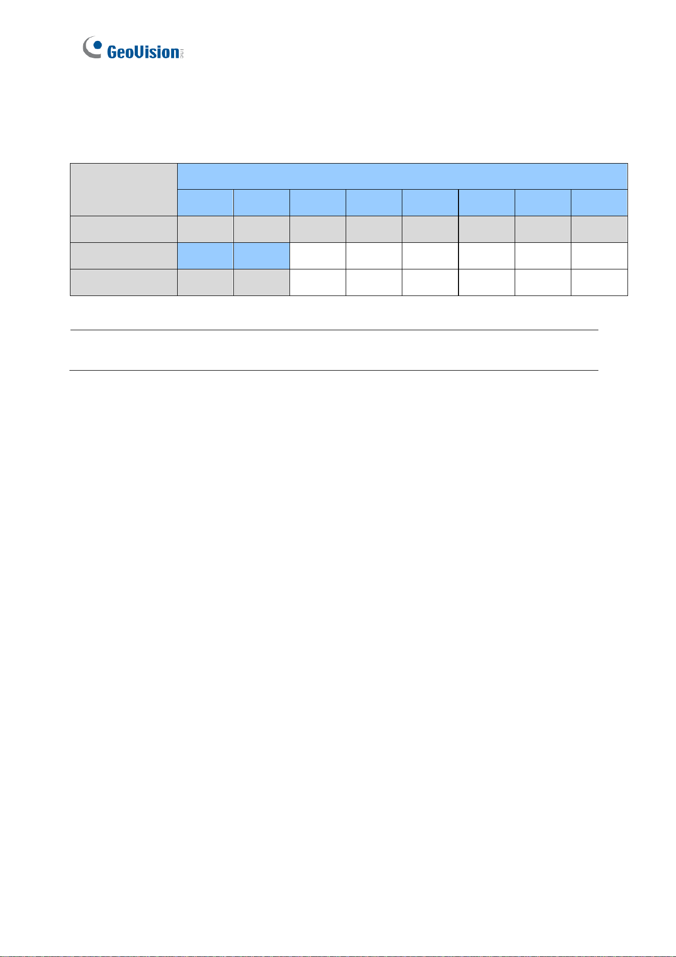
1.2 Firmware and GV-ASManager Compatibility
The GV-ASManager versions compatible with GV-AS1620 are listed below.
Software
GV-AS1620 Firmware Version
V1.00
V1.01
V1.02
V1.03
V1.04
V1.05
V1.10
V1.11
GV-ASManager
V5.2.0
V5.3.0
V5.3.0
V5.3.0
V5.3.2
V5.3.3
V6.0.1
V6.0.1
V1.13
V1.14
-
-
-
-
-
-
GV-ASManager
V6.0.2
V6.1.1
-
-
-
-
-
-
1.3 Packing List
1. GV-AS1620
2. Warranty Card
3. Download Guide
IMPORTANT: GV-AS1620 firmware V2.00 or later is designed for GV-Cloud Access Control
applications.
Introduction
3
1
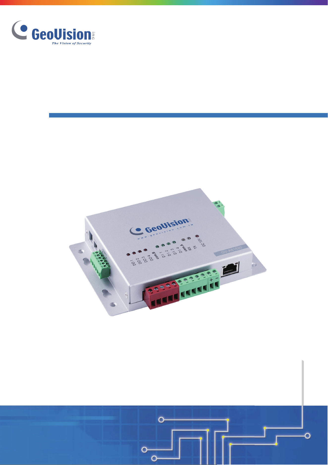
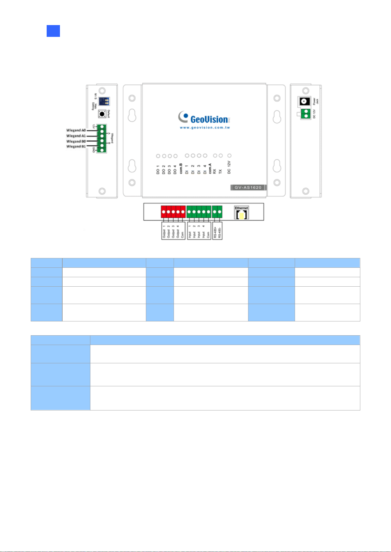
1.4 Overview
Figure 1-1
Pin
Definition
Pin
Definition
Pin
Definition
DO 1
Lock
DI 1
Door Contact
Wiegand A
Entry Reader
DO 2
Alarm
DI 2
Exit Button
Wiegand B
Exit Reader
DO 3
LED / Beeper for
Access Granted
DI 3
Fire Contact
RS-485 +/-
RS-485 / OSDP
Reader
DO 4
LED / Beeper for
Access Denied
DI 4
Tamper Contact
Control
Definition
DC 12V
Power output for compatible devices connected
Web Setting
Switch
GUI security lock. Switch on to lock all system configurations on the Web interface of the
controller.
Default Button
Reset the controller to factory default if it is not functioning correctly. To do this, hold down
the Default button with a pointy object such as the tip of a pen for 3 to 5 seconds.

Installing on a Network
4
2
Chapter 2 Installing on a Network
Through a network connection, you can access the controller’s Web interface and connect it
to access control software for more comprehensive management. There are three ways to
set up the controller on network.
1. By default, when the controller is connected to a network with a DHCP server, a
dynamic IP address will be assigned to the controller. See 2.1 Checking the Dynamic IP
Address to look up its IP address.
2. When the DHCP server on your network is unavailable or disabled, the controller is
accessible by its default IP address 192.168.0.100. See 2.2 Configuring the Static IP
Address.
3. You may also use a DDNS (Dynamic Domain Name System) server to access the
controller. For details on domain name service, see 2.3 Configuring DDNS Connection.
5
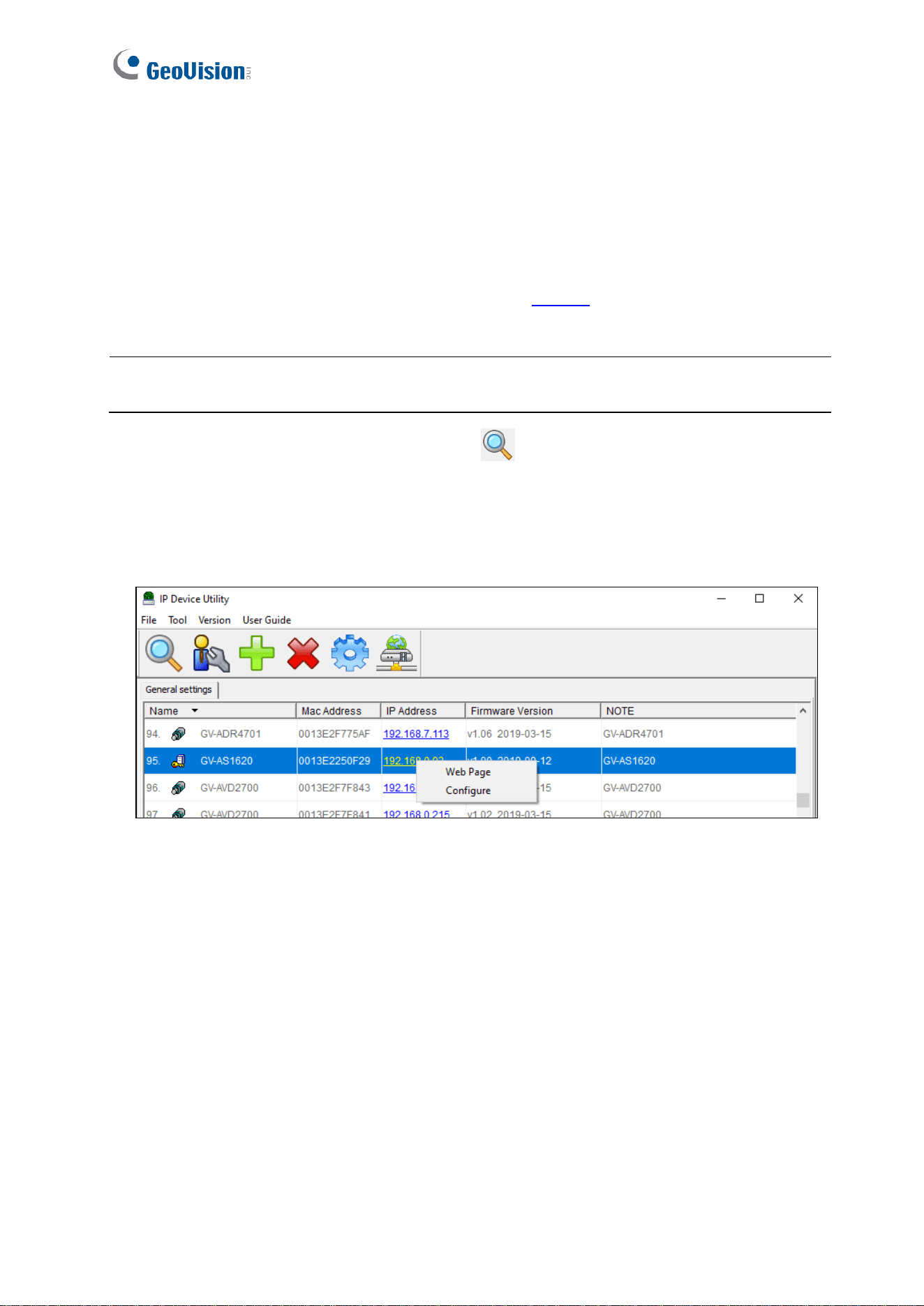
2.1 Checking the Dynamic IP Address
Follow the steps below to look up the IP address and access the Web interface of the
controller.
1. Download and install GV-IP Device Utility from our website.
2. On the GV-IP Device Utility window, click the button to search for the IP devices
connected in the same LAN.
3. Click the Name or Mac Address column to sort.
4. Find the controller with its MAC address, click on its IP address and select Web Page.
Figure 2-1
5. When the login dialog box appears, type the default admin for both username and
password and click OK to log in.
Note: The PC installed with GV-IP Device Utility must be under the same LAN as the
controller you wish to configure.
Installing on a Network
6
2
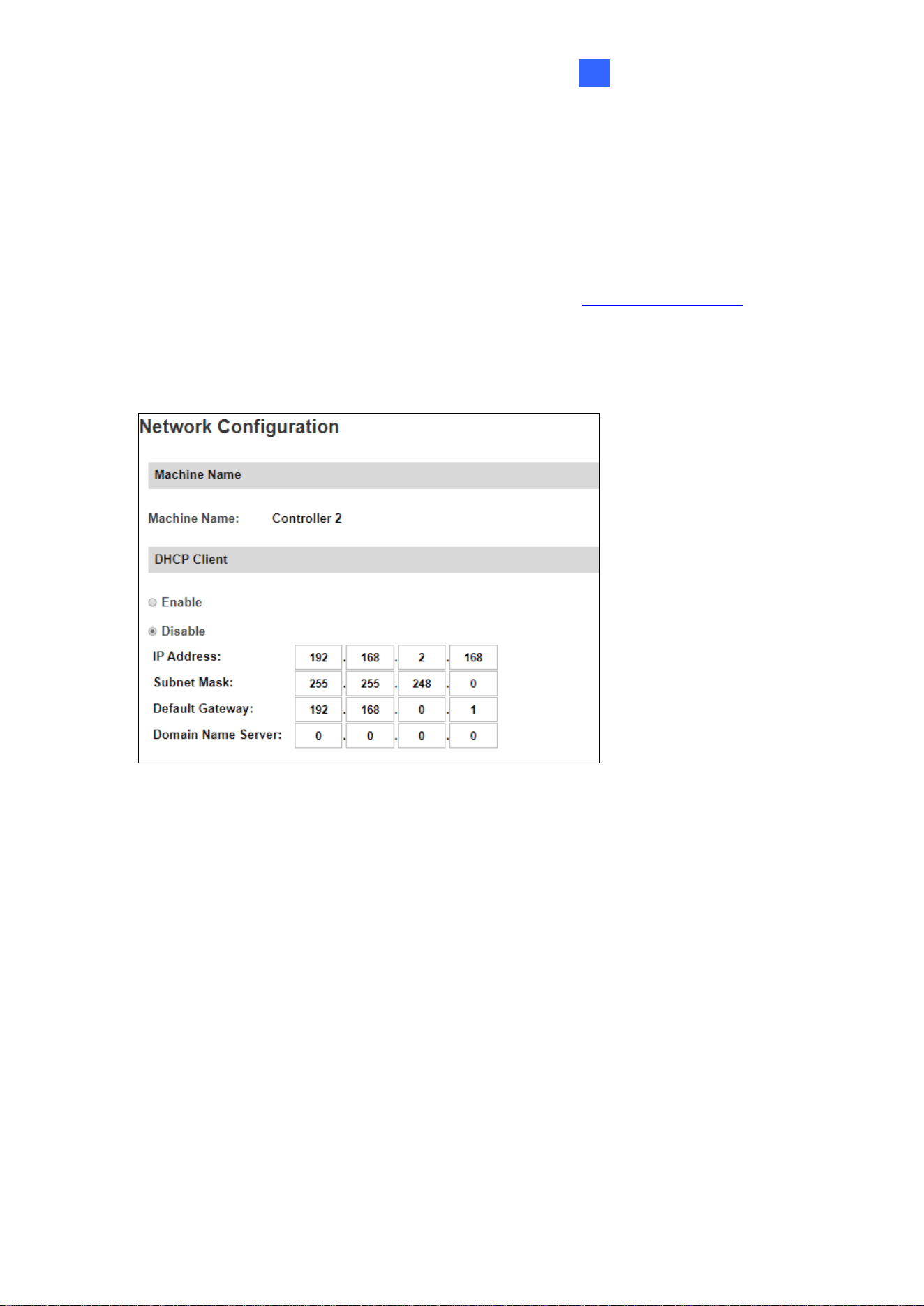
2.2 Configuring the Static IP Address
By default, the controller uses a DHCP connection. However, you can follow the instructions
below to configure a static IP address.
1. Open an Internet browser, and type the default IP address https://192.168.0.100 or the
dynamic IP address. The login dialog box appears.
2. Type default value admin for both username and password, and click OK. This page
appears.
Figure 2-2
3. In the DHCP Client section, select Disable. Type the static IP address information,
including IP Address, Subnet Mask, Default Gateway and Domain Name Server.
4. Click Submit. When the setting is complete, the Status field will indicate Register
Success. Then the controller can be accessed with this fixed IP address.
2.3 Configuring DDNS Connection
DDNS (Dynamic Domain Name System) provides another way to access the controller when
using a dynamic IP. DDNS assigns a domain name to the controller so that it can always be
accessed using the domain name. The controller supports two DDNS services: GeoVision
DDNS and DynDNS.org (Dynamic Network Services Inc.).
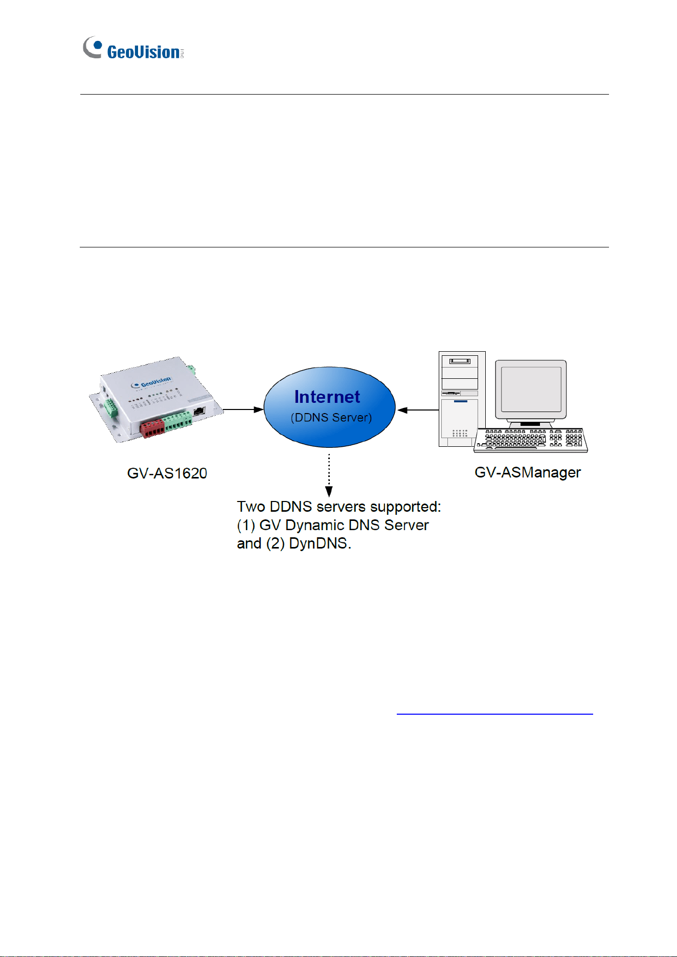
7
To enable the DDNS function, you first should register a domain name from one of the two
supported DDNS service provider’s websites.
Figure 2-3
2.3.1 Registering a DDNS Domain Name
To obtain a domain name from the GeoVision DDNS Server:
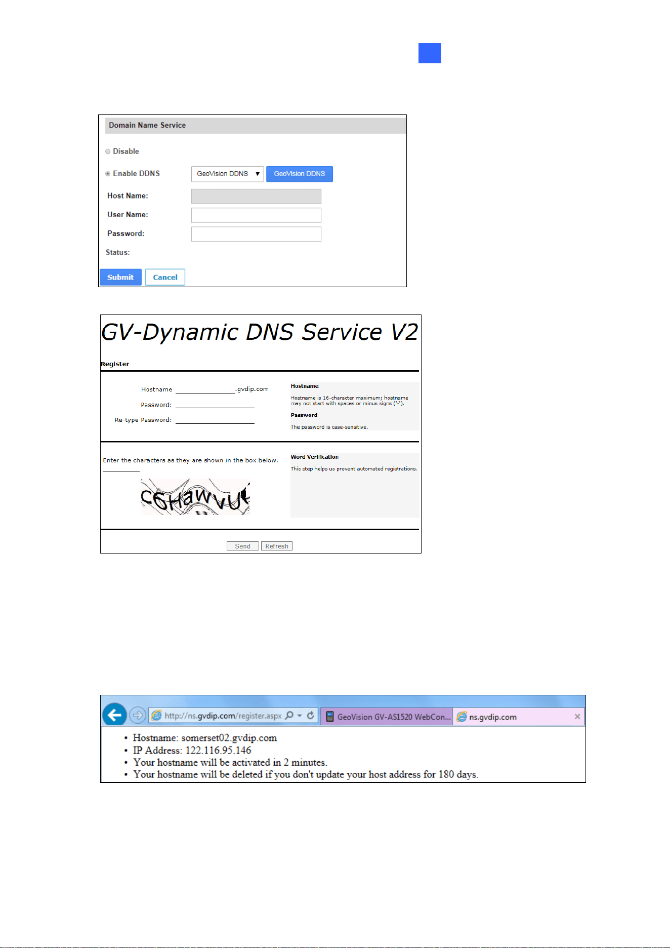
1. Click the GeoVision DDNS button on the Network Configuration page (Figure 2-2). Or
open an Internet browser, and type the Web address http://ns.gvdip.com/register.aspx.
The GV-Dynamic DNS Service V2 page appears.
Note:
1. Dynamic DNS uploads IP addresses over the Internet through ports 80 and 81. If your
controller is behind a router or firewall, make sure the two ports are enabled. Dynamic
DNS will only upload global IP addresses. If your controller uses virtual IP, NAT port
mapping should be done first.
2. The DDNS service is provided purely as a favor to you. We hope it simplifies the process
of trying to connect an IP video device to the network. GeoVision does not and cannot
warrant that the DDNS service will be uninterrupted or error free. Please read Terms of
Service carefully before using the service.
Installing on a Network
8
2
Figure 2-4
Figure 2-5
2. Type a Hostname and Password based on the requirements noted on the page.
3. Type the characters or numbers shown for word verification, and click Send.
4. When the registration is complete, this page appears. The Hostname is the domain
name, consisting of the registered username and “gvdip.com”, e.g.
somerset02.gvdip.com.
Figure 2-6
9
2.3.2 Configuring the Controller on Internet
After acquiring a domain name from the DDNS Server, you need to configure the registered
domain name on the controller in order to access the unit by the domain name on Internet.
1. Open an Internet browser, and type the controller’s IP address. The login dialog box
appears.
2. Type the username and password of the controller, and click OK. The Network
Configuration page appears.
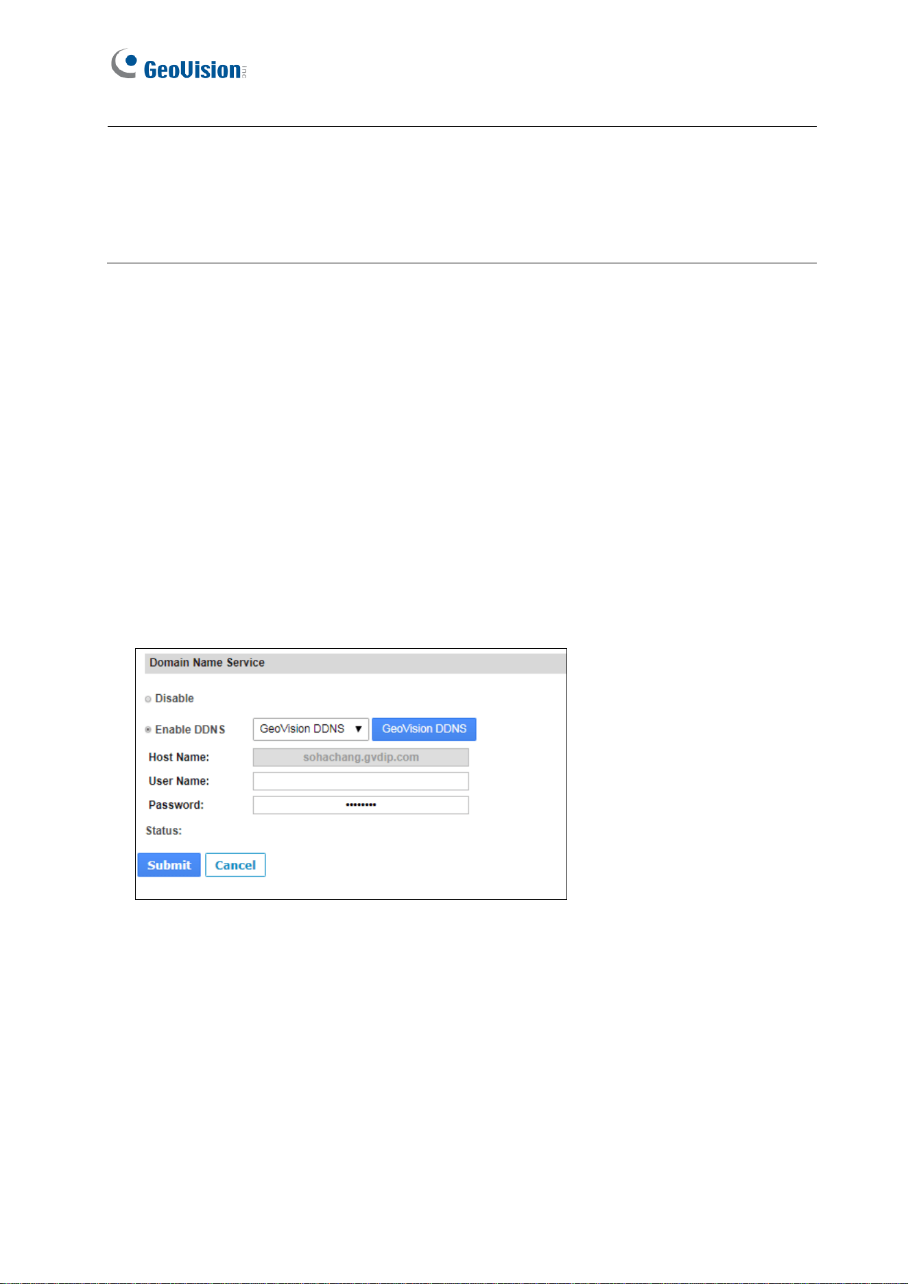
3. Select Enable DDNS.
4. Type Host Name, User Name and Password that are registered on the DDNS Server. If
GeoVision DDNS is used, the system will automatically bring up the Host Name.
Figure 2-7
5. Click Submit. When the setting is complete, the Status field will indicate: Register
Success. Then the controller can be accessed with the domain name.
Note:
1. The registered username will be invalid when it is not used for three months.
2. For GV-AS1620 firmware V2.00 or later: Optionally, you can type the backup DNS next
to Override Primary Domain Name Server under the DHCP Client section to prevent
the malfunction of the set DNS.
The Web Interface for GV-ASManager Connection
10
3
Chapter 3 The Web Interface for GV-
ASManager Connection
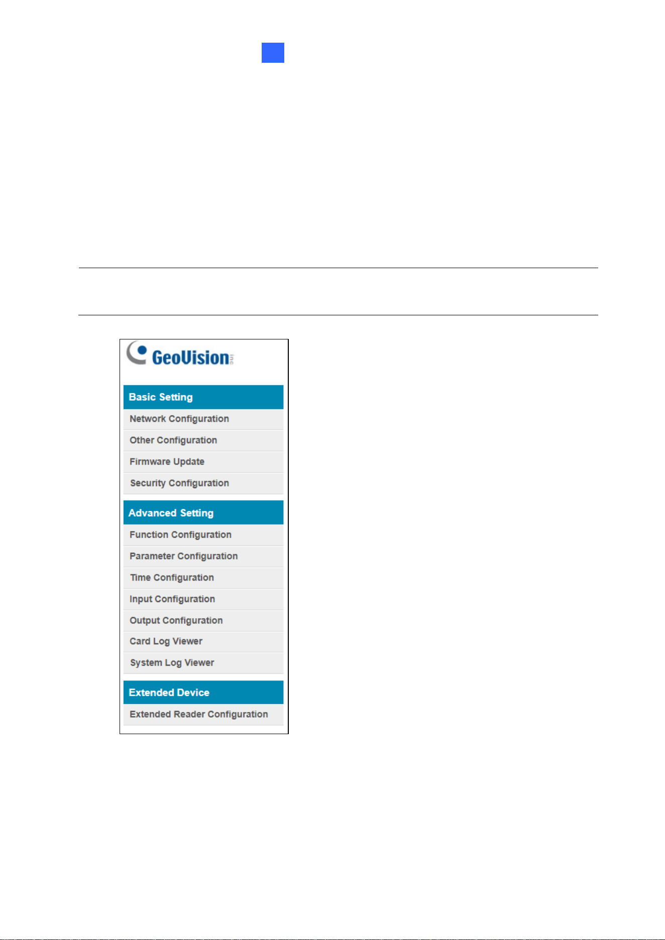
After installing the controller on the network, you can configure the controller’s settings on
the Web interface. The left menu of the Web interface is divided into three sections: Basic
Setting, Advanced Setting and Extended Device.
Figure 3-1
IMPORTANT: The GV-ASManager applications are only available for GV-AS1620 firmware
V1.XX or earlier. See 1.2 Firmware and Software Compatibility for details.
11
3.1 Basic Settings
The Basic Settings section covers general system settings, firmware update and user
account settings. For details on Network Configuration, refer to Chapter 2 Installing on a
Network.
3.1.1 System Setup
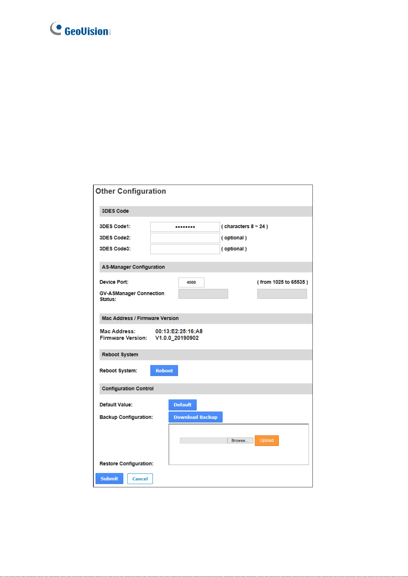
In the left menu, click Other Configuration. This page appears.
Figure 3-2

The Web Interface for GV-ASManager Connection
12
3
◼ 3DES Code 1-3: Stands for Triple DES (Data Encryption Standard). Type up to three
different keys for data encryption. The default 3DES Code1 is 12345678.
◼ Device Port: Keeps the default value 4000. Or modify it to match that of GV-ASManager.
◼ GV-ASManager Connection Status: If the controller is successfully connected to GV-
ASManager, the IP address of GV-ASManager will be automatically brought up here.
◼ Mac Address: Indicates the MAC address of the network medium.
◼ Firmware Version: Indicates the current firmware version of the controller.
◼ Reboot System: Performs a warm boot of the controller. This operation will keep the
current system configuration.
[Configuration Control]
◼ Default Value: Resets all configuration parameters to factory settings. This may take 5
seconds to complete.
◼ Backup Configuration: To backup controller settings, click Download Backup. A .bin
file will be exported. You can then import the file to another controller to avoid setting
each controller individually. Note that network settings, such as IP address and hardware
ID, will NOT be included in the backup file.
◼ Restore Configuration: To import controller settings, click Browse, select the .bin file
previously exported, and click Upload.
13
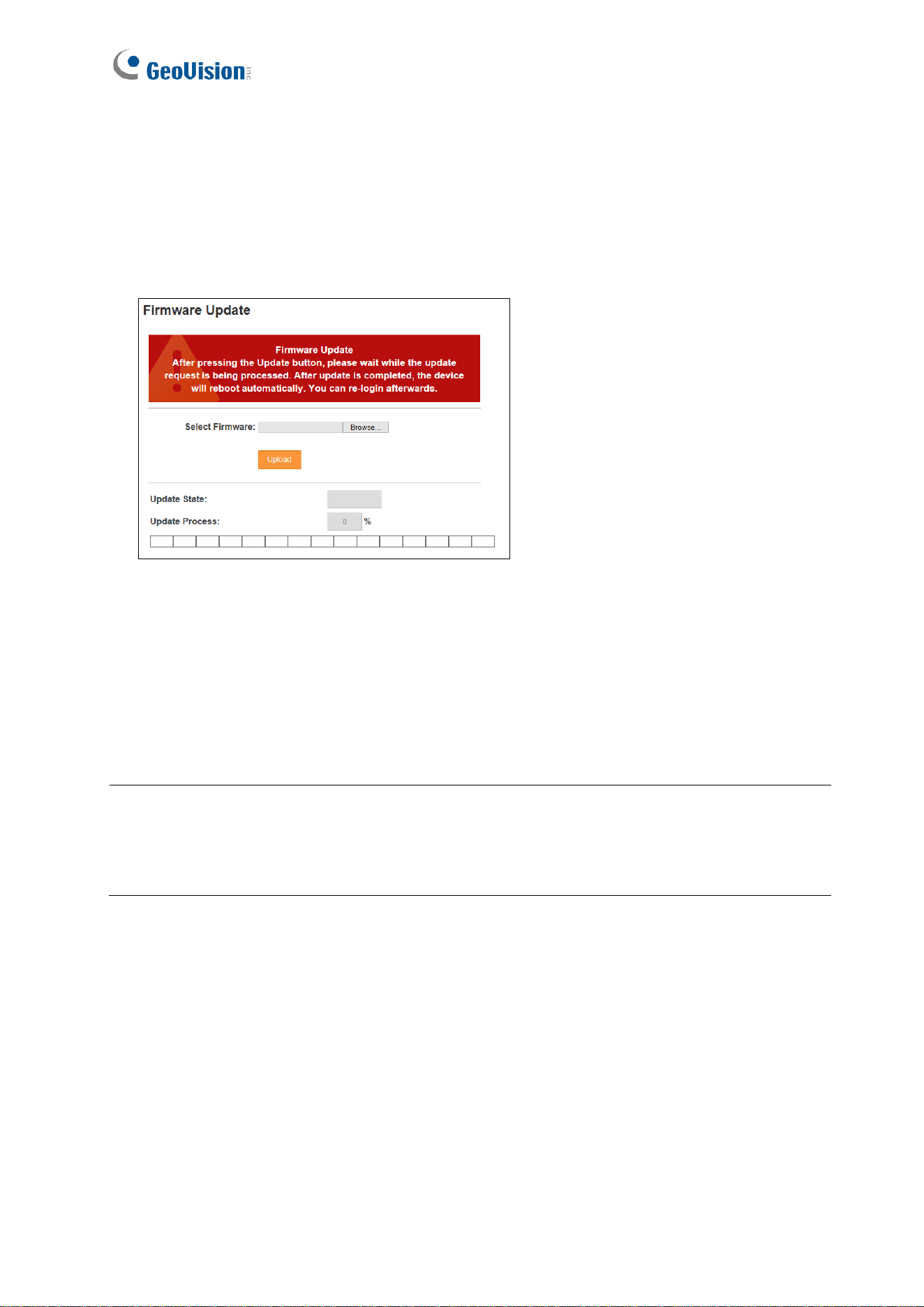
3.1.2 Firmware Update
Follow the steps below to update the firmware of the controller.
1. In the left menu, click Firmware Update. This page appears.
Figure 3-3
2. Click Browse and select the firmware file.
3. Click Upload. This update process may take 60 seconds to complete.
4. When the update is complete, you will be asked to reboot the system.
5. Click OK. The controller is rebooted.
Note:
1. Make sure the controller remains powered on during the firmware upgrade.
2. The controller must be rebooted following the firmware update. Without a reboot, the
firmware update is not complete.
The Web Interface for GV-ASManager Connection
14
3
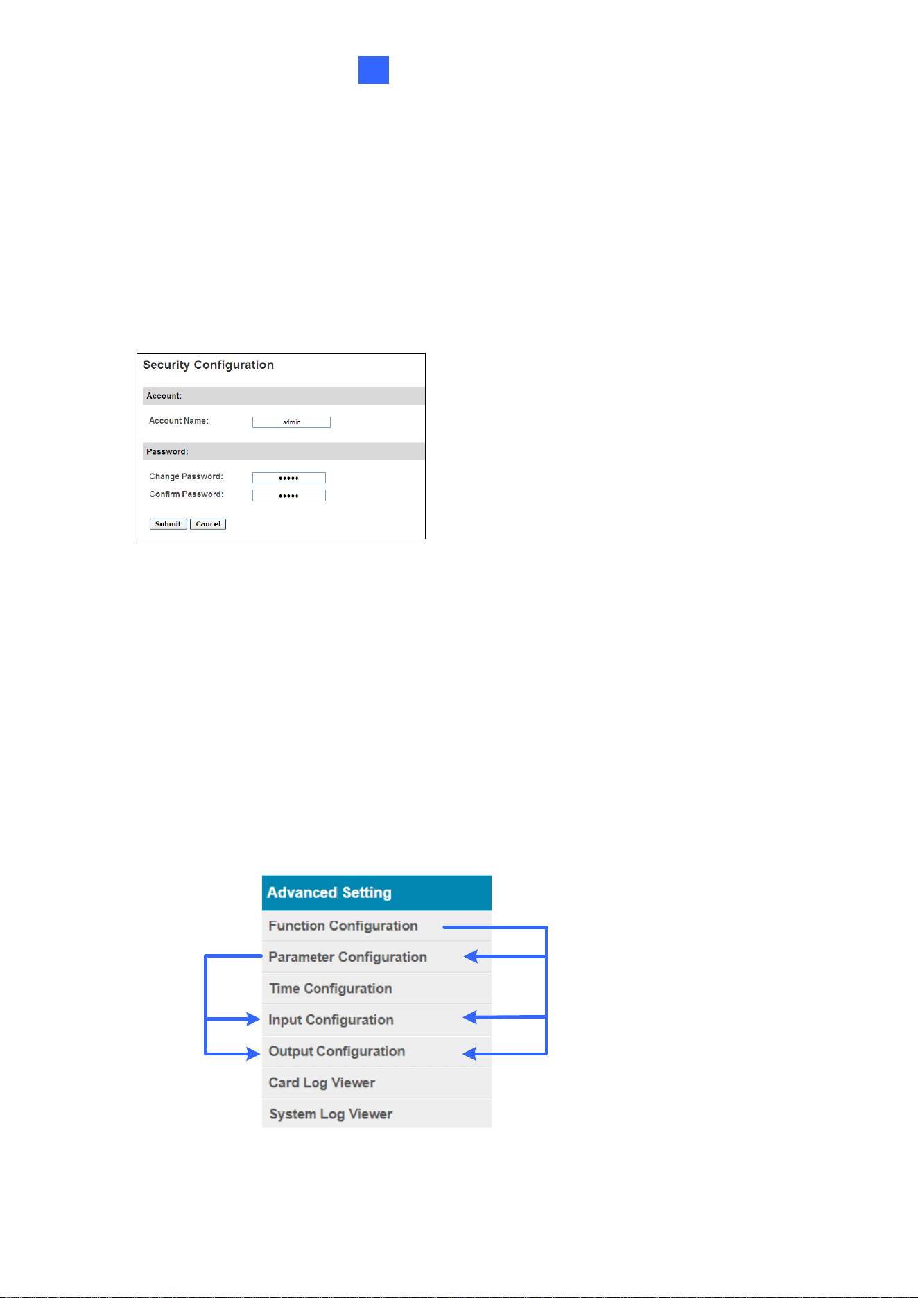
3.1.3 Security Configuration
Follow the steps below to change the login ID and password.
1. In the left menu, click Security Configuration.
2. Modify the login name and password. The password is case sensitive and is limited to
alphabets and numbers.
Figure 3-4
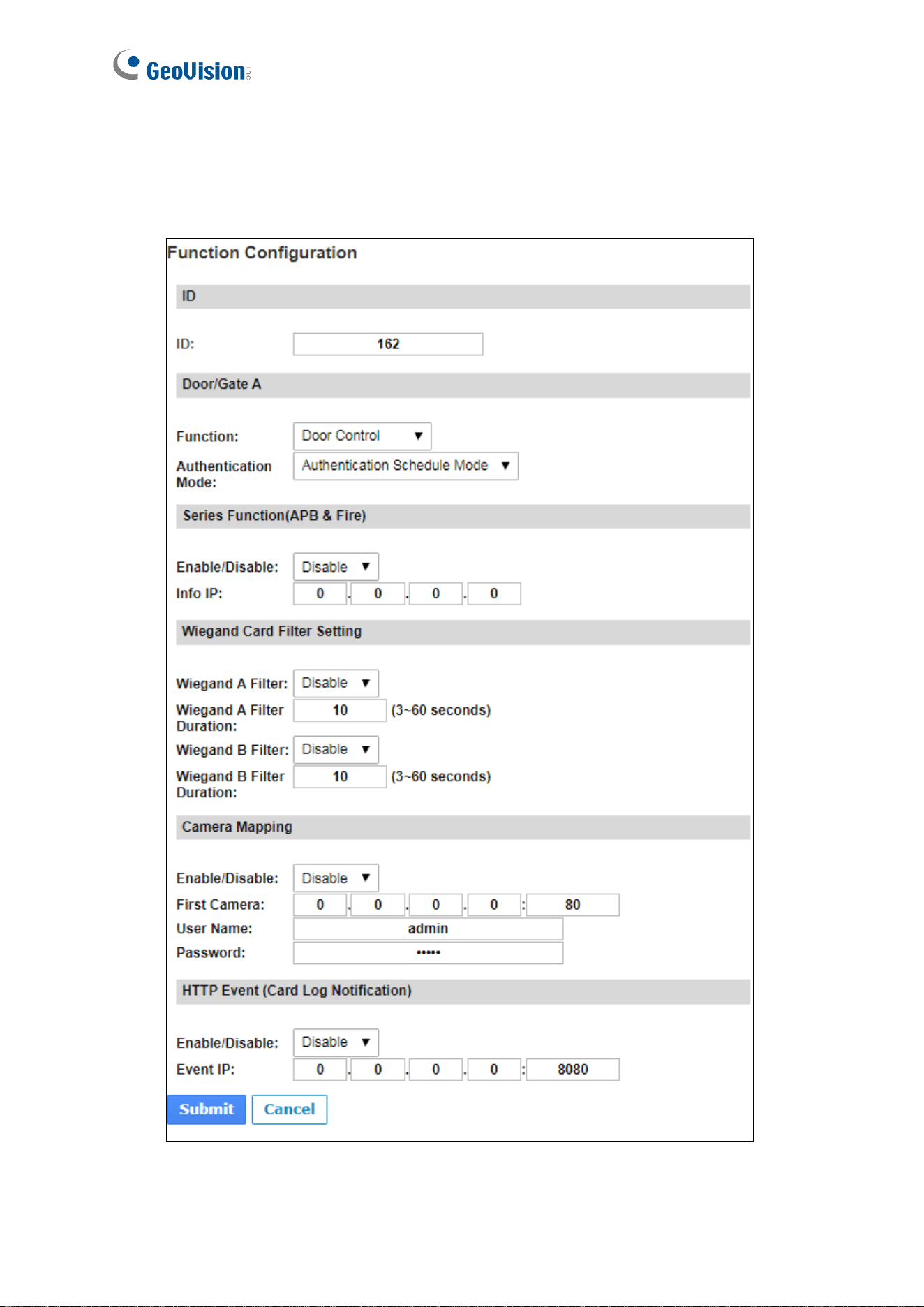
3.2 Advanced Settings
Under Advanced Settings, you can configure door settings, turn on alarms, set the device
time, edit input / output functions and view system logs.
Changes made on some of the Advanced Settings pages will affect the options available on
other pages. The relationships between each Advanced Settings page are depicted in the
diagram below.
Figure 3-5
15
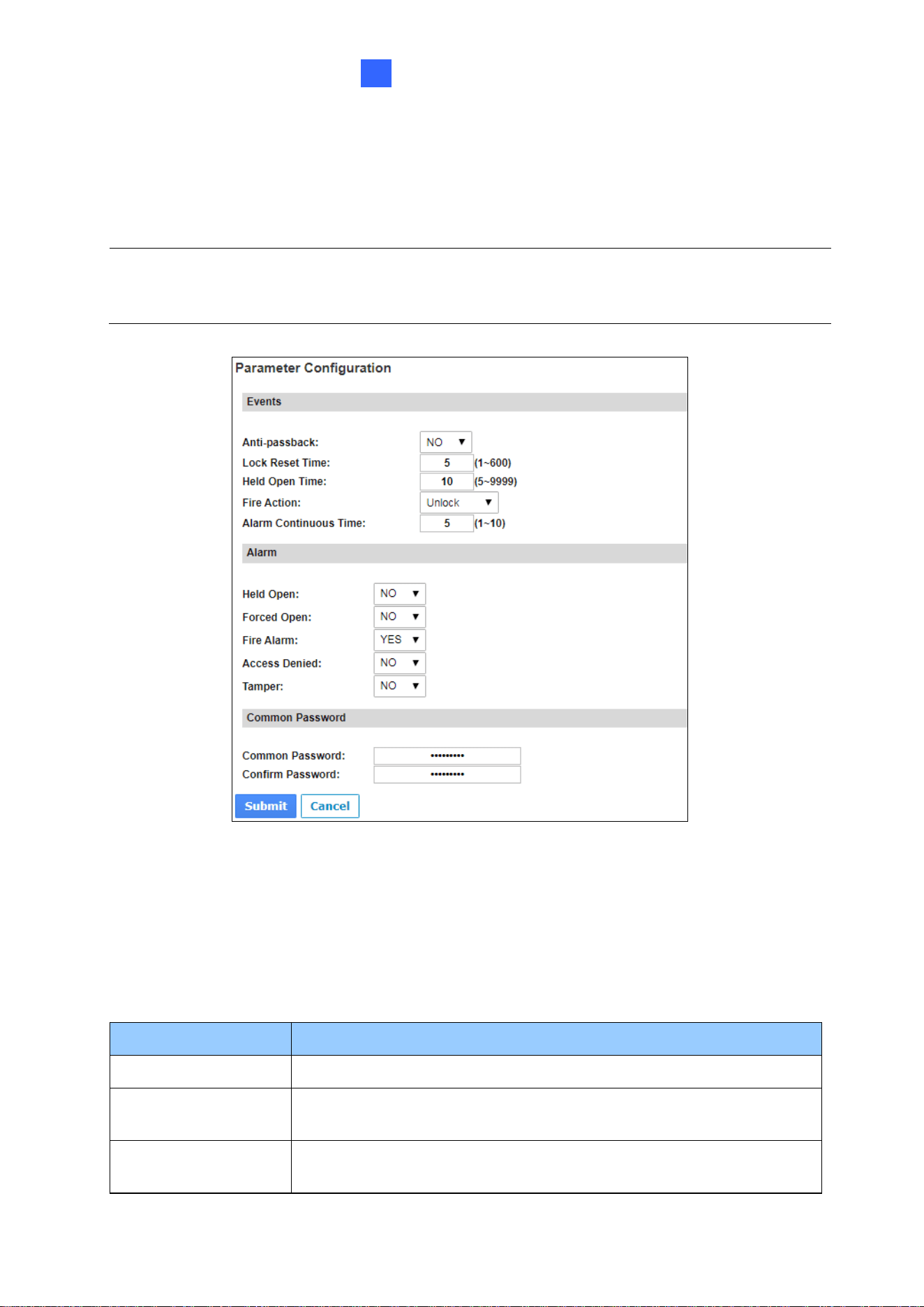
3.2.1 Function Configuration
In the left menu, click Function Configuration. This page appears.
Figure 3-6

The Web Interface for GV-ASManager Connection
16
3
[ID]
Enter the ID number for the controller. This ID is used by GV-ASManager to differentiate
among multiple controllers. ID number can only be between 1 and 1000.
[Door/Gate A]
Select the function type and authentication mode for the use of the door/gate.
◼ Function: Define the function of the controller connected to the door/gate which is used
for the door, parking lot or elevator.
◼ Authentication Mode: Select the authentication mode for the door/gate.
Local Unlock Mode: Remains open. The held-open state cannot be cleared
through GV-ASManager.
Local Lock Mode: Remains locked. The locked state cannot be cleared through
GV-ASManager.
Fixed Card Mode: Grants access after the card is presented or a passcode is
entered, and ignores the authentication schedule of GV-ASManager.
Fixed Card Mode + PIN Mode: Grants access after the card is presented and the
card’s PIN code entered too. Ignores the authentication schedule of GV-ASManager.
Fixed Card/Common Mode: Grants access after the card is presented or after the
door/gate’s password is entered. Ignores the authentication schedule of GV-
ASManager.
Authentication Schedule Mode: Follows the authentication schedule set on GV-
ASManager.
Local Lock Down: Locks down the door and denies access when the card is
presented. Ignores the Lock Time setting and APB setting.
Note: To grant access to a card in Local Lock mode, click the Access Monitor button on
GV-ASManager, right-click on the card to select New/Edit Card and select Disable Lock
Card / Disable APB / Allow Access during Lockdown Mode.

17
[Series Function (APB & Fire)]
You can set Anti-Passback and fire sensor functions across multiple controllers. The Anti-
Passback means that a card used on an entry door/gate cannot access the same entry
door/gate again unless it has been used on a corresponding exit door/gate. For details on
setup, see Chapter 6 Anti-Passback on GV-ASManager User’s Manual.
For the fire sensor function, when the fire sensor of the associated controller is triggered, the
fire sensor on GV-AS1620 will also be activated.
◼ Enable/Disable: Enables or disables Anti-Passback and fire sensor functions.
◼ Info IP: Enter the IP address of the next corresponding controller.
[Wiegand Card Filter Setting]
◼ Wiegand A/B Filter: Enable to avoid recording repeated access logs, from the same
card via Wiegand port A or B, within the duration set.
Wiegand A/B Filter Duration: Set the duration of filter, from 3 ~ 60 seconds.
[Camera Mapping]
You can assign a camera to capture snapshots upon card presented. The captured
snapshots will be saved to the built-in flash drive of GV-AS1620 and then transferred to the
Access Log on GV-ASManager whenever GV-ASManager resumes connection after it has
been disconnected.
◼ Enable/Disable: Enables or disables the camera mapping function.
◼ First Camera: Type the IP address of the assigned camera to take snapshots.
Type the User Name and Password of the camera to complete the mapping process.
[HTTP Event (Card Log Notification)]
Select Enable to send access and event logs of the controller to the configured event IP
address and Port number.
Note: This function is supported only on GV IP cameras except GV-EBD / ABL / ADR / AVD /
TDR / TBL / TVD series, GV-VD8700 and FD8700-FR.
The Web Interface for GV-ASManager Connection
18
3
3.2.2 Parameter Configuration
In the left menu, click Parameter Configuration. This page appears.
Figure 3-7
[Events]
Set the parameters for the events. The options available vary depending on Door Control,
Parking Control and Elevator Control selected in the Function Configuration page
(Figure 3-6):
Option
Description
Anti-Passback
Enables or disables the Anti-Passback function.
Lock Reset Time
Sets the time (1 to 600 sec.) that a door remains open after which
the door will automatically be locked.
Held Open Time
Sets the time (5 to 9999 sec.) that a door can be held open before
an alarm is generated.
IMPORTANT: Once connected to GV-AS1620, GV-ASManager will load its parameters to
the controller. That means some of the Parameter Settings you have configured here may be
overwritten by GV-ASManager later.
19
Fire Action
Locks or unlocks the door when a fire condition occurs. Otherwise,
remains the door’s current state by selecting Unchanged.
Alarm Continuous
Time
Sets the time (1 to 10 sec.) that the alarm will continuously go off
before it ends.
Relay On Time
Sets the time (1 to 600 sec.) that a gate remains open after which
the gate will automatically be closed.
[Alarm]
Select Yes or No to enable or disable the alarm function. The options available vary
depending on Door Control, Parking Control and Elevator Control selected in the
Function Configuration page (Figure 3-6):
If you have defined the alarm conditions in the Input Configuration (Figure 3-9) and Output
Configuration (Figure 3-10) pages, remember to activate the corresponding alarms here;
otherwise, even though the alarm conditions are met, the expected alarm will not be
triggered. The default settings for all the alarms are set to NO.
Option
Description
Held Open
This alarm activates whenever the door is held open over the
specified time period.
Forced Open
This alarm activates whenever the door is opened by force.
Fire Alarm
This alarm activates whenever fire is detected.
Access Denied
This alarm activates whenever entry is denied due to invalid card or
password presented.
Tamper
This alarm activates whenever the sensor for tampering alarm is
triggered. The tampering alarm sensor must be installed separately
and the triggering conditions depend on the type of sensor used,
such as the controller’s cabinet being opened.
[Common Password]
When Fixed Card/Common Mode is selected as Authentication Mode in the Function
Configuration (Figure 3-6) page, you can gain access by using a card or entering this
Common Password (door’s password).
The Web Interface for GV-ASManager Connection
20
3
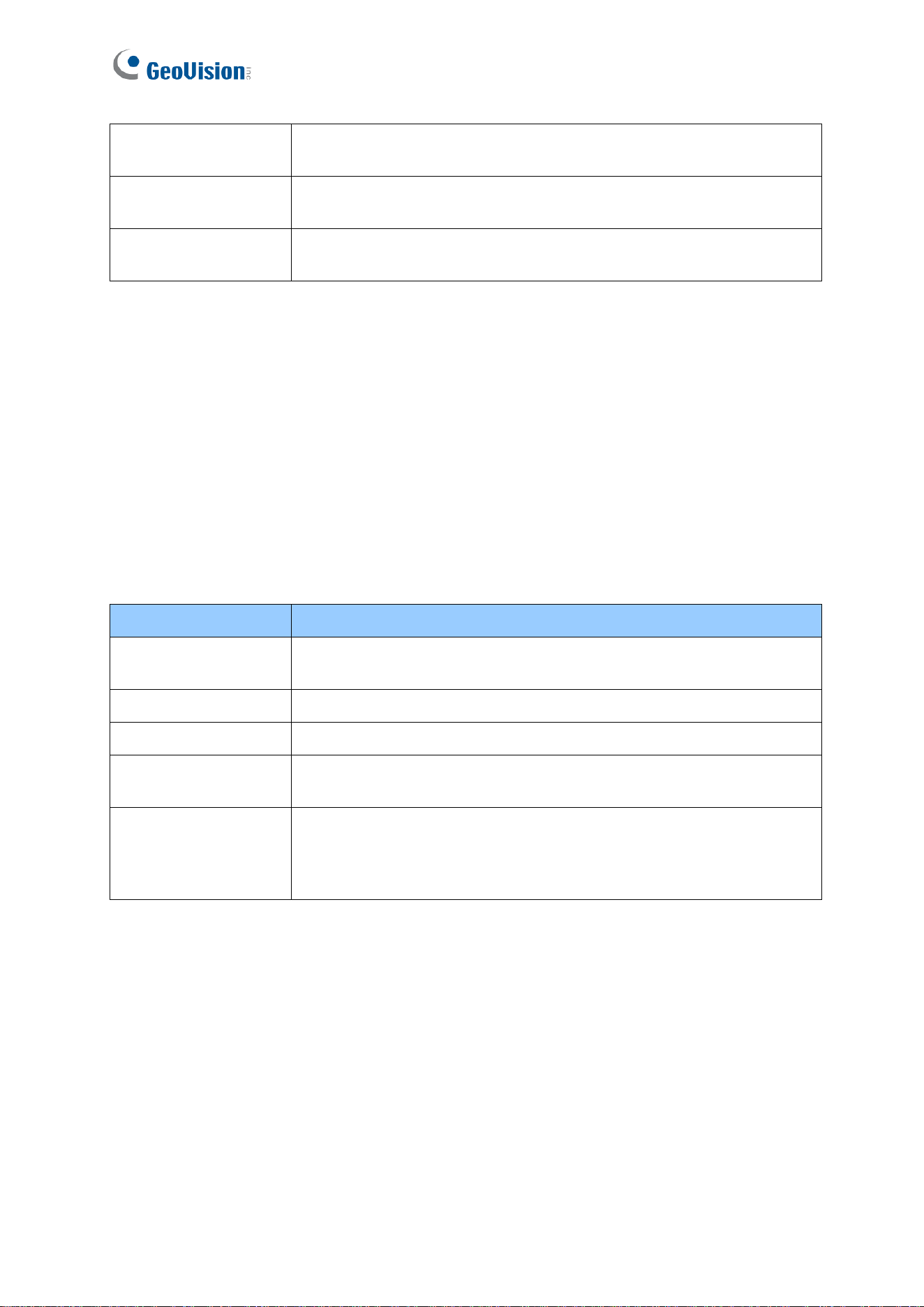
3.2.3 Time Configuration
In the left menu, click Time Configuration to set up system time, local time and daylight-
saving time period.
Figure 3-8
[System Local Time] Displays the current data, time and time zone of the controller.
[Local Time]
◼ Disable: Disable the manual configuration of time and date.
◼ Setup: Configure the time and date of the controller manually. You can click Current
local time to synchronize the controller’s date and time with those of the local PC.
[Daylight Savings Time (DST)]
◼ Disable: Disable the manual configuration of DST.
◼ Time Zone: Enable the manual configuration of DST by setting Start Time and Stop
Time for the DST period.
21
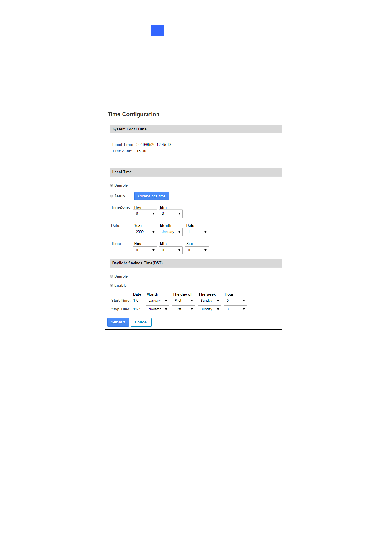
3.2.4 Input Configuration
In the left menu, click Input Configuration to define the input devices connected to the
controller. Set the input status to either NO (normally open) or NC (normally close).
Figure 3-9
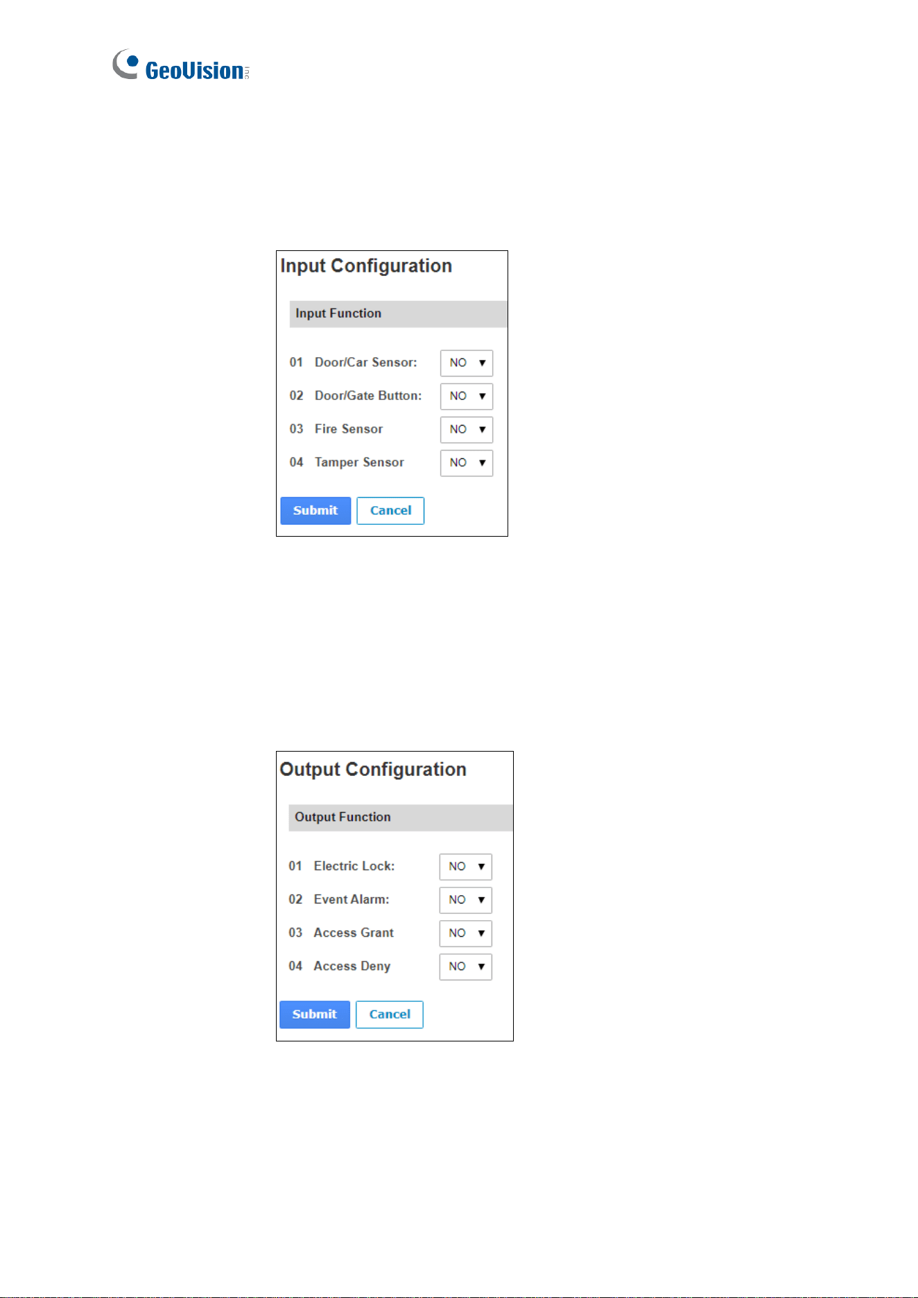
3.2.5 Output Configuration
In the left menu, click Output Configuration to define the output devices connected to the
controller. Set the output status to either NO (normally open) or NC (normally close).
Figure 3-10
The Web Interface for GV-ASManager Connection
22
3
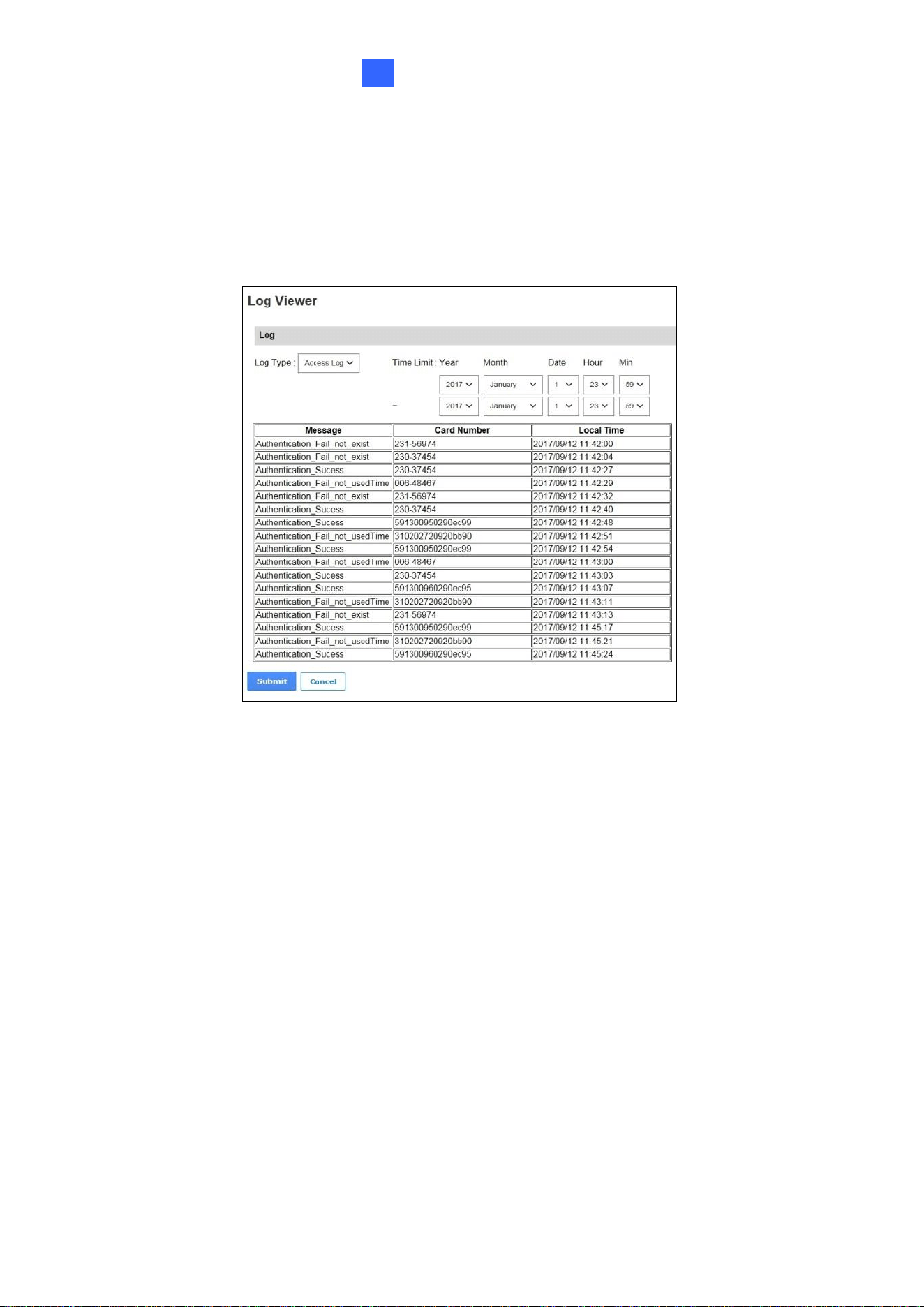
3.2.6 Log Viewer
In the left menu, click Card Log Viewer to search for the log data. The log entries are only
created when the controller is disconnected from GV-ASManager. Only up to 100 log entries
of Event Log / Access Log on the Web interface can be retrieved at a time.
Figure 3-11
3.2.7 System Log Viewer
In the left menu, click System Log Viewer to view the current system status and dump data
that can be used by service personnel for analyzing problems.
23
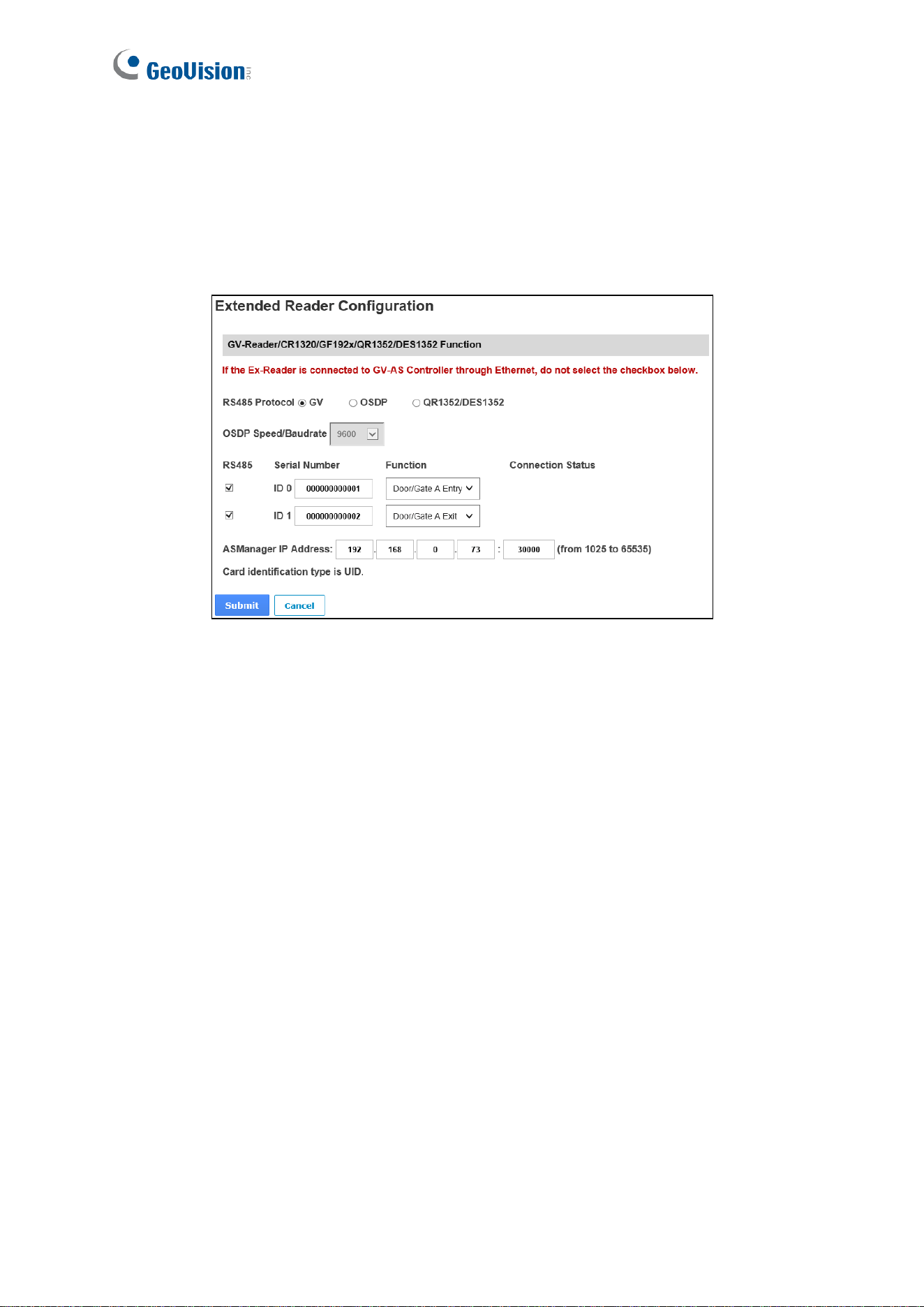
3.3 Extended Device
In the left menu, click Extended Reader Configuration to define the readers connected to
the controller via RS-485 or network, and then use the Function dropdown list to select the
door usage associated with the reader.
Figure 3-12
[Protocol]
◼ GV: For the following GeoVision readers, select this protocol.
GV-RK1352 / R1352 / DFR1352: Select the RS-485 checkbox and type the Serial
Number of the reader. The ID number located next to the serial number will be
assigned to the reader.
GV-Reader 1251 / Reader 1352 V2: Select the RS-485 checkbox and leave the
serial number field blank. Note that the ID number located next to the serial number
needs to match the reader’s ID number defined by the DIP switches on the reader.
GV-GF1921 / GF1922 / CR1320 / FR2020: Type the MAC address of the
fingerprint reader or the camera and do not select the RS-485 checkbox.
GV-CR420: Select the RS-485 checkbox only if the GV-CR420 is connected to the
controller through RS-485. If the reader is connected via network do not check the
RS485 box. Type the MAC address of GV-CR420 if you using the latest firmware.
The Web Interface for GV-ASManager Connection
24
3
◼ OSDP: For OSDP compliant readers, e.g. GV-RKD1352, select this protocol and select
the paired ID No. of the reader (ID #1 ~ #2).
◼ QR1352/DES1352: For GV-QR1352 / DES1352 / R1354 reader, select this protocol and
select the paired ID No. of the reader.
[ASManager Server IP Address] To allow GV-ASManager to receive data from the GV-
AS1620, type the IP address and port of GV-ASManager.
Click Submit. The green Connection Status indicates the successful connection between
GV-AS1620 and the reader whereas a red status indicates otherwise.
Note:
1. For the RS-485 interface, connect just one of the following readers to GV-AS1620: GV
RS-485 readers, OSDP compliant readers, and GV-QR1352/DES1352 readers.
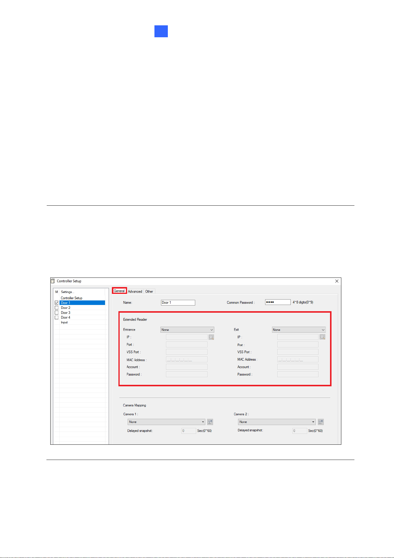
2. When the RS-485 checkbox is not selected, the Extended Reader Configuration page
can be used to configure network readers. Moreover, network readers can also be
quickly and easily set up on GV-ASManager which automatically retrieves the reader’s
MAC address: Controller Setup > General tab > Extender Reader.
Figure 3-13
The Web Interface for GV-Cloud Access Control Connection
25
4
Chapter 4 The Web Interface for GV-Cloud
Access Control Connection
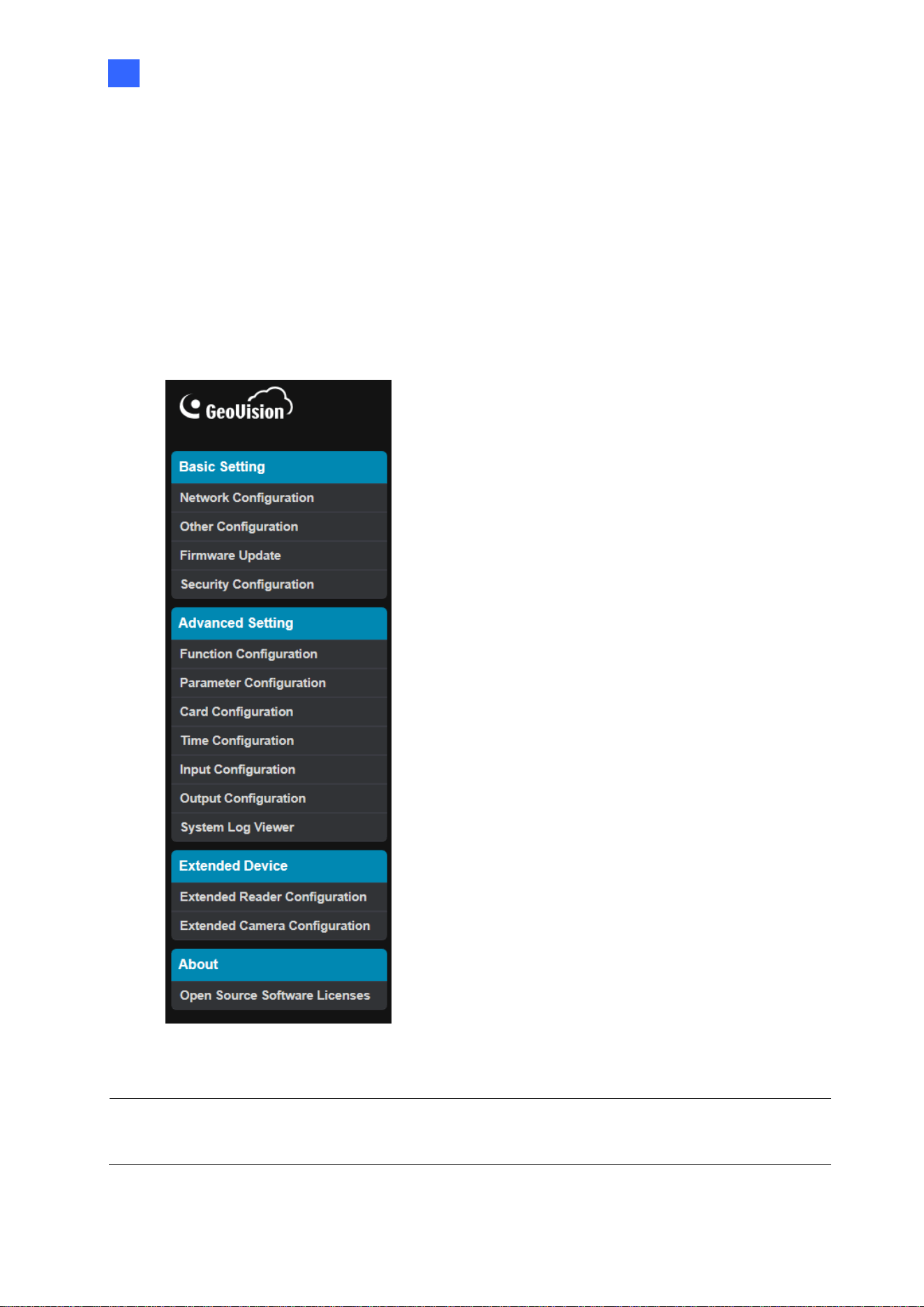
After installing the controller on the network, you can configure the controller’s settings on
the Web interface. The left menu of the Web interface is divided into three sections: Basic
Setting, Advanced Setting and Extended Device.
Figure 4-1
IMPORTANT: The GV-Cloud Access Control applications are only available for GV-AS1620
firmware V2.00 or later.
26
4.1 Basic Settings
The Basic Settings section covers general system settings, firmware update, and GV-Cloud
Access Control connection settings. For details on Network Configuration, refer to Chapter 2
Installing on a Network.
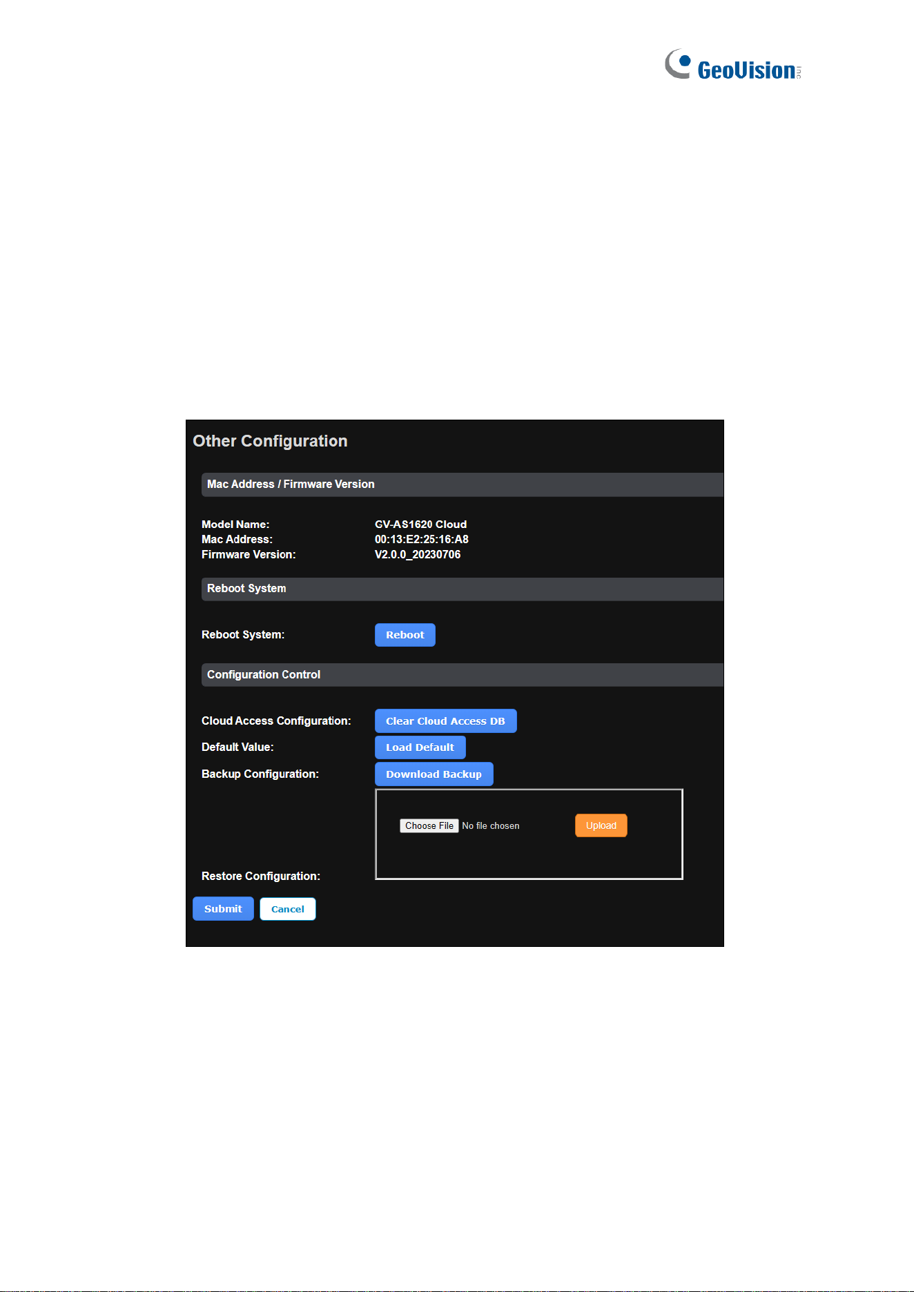
4.1.1 System Setup
In the left menu, click Other Configuration. This page appears.
Figure 4-2

The Web Interface for GV-Cloud Access Control Connection
27
4
[Mac Address / Firmware Version]
◼ Mac Address: Indicates the MAC address of the controller.
◼ Firmware Version: Indicates the current firmware version of the controller.
[Reboot System]
◼ Reboot System: Performs a warm boot of the controller. This operation will keep the
current system configuration.
[Configuration Control]
◼ Cloud Access Configuration: Clears the database of GV-AS1620. After reconnecting to
GV-Cloud Access Control, the system will automatically synchronize the user and card
data from GV-Cloud Access Control to GV-AS1620.
◼ Default Value: Resets all configuration parameters to factory settings. This may take 5
seconds to complete.
◼ Backup Configuration: To backup controller settings, click Download Backup. A .bin
file will be exported. You can then import the file to another controller to avoid setting
each controller individually. Note that network settings, such as IP address and hardware
ID, will NOT be included in the backup file.
◼ Restore Configuration: To import controller settings, click Browse, select the .bin file
previously exported, and click Upload.

28
4.1.2 Firmware Update
See 3.1.2 Firmware Update for details.
The Web Interface for GV-Cloud Access Control Connection
29
4
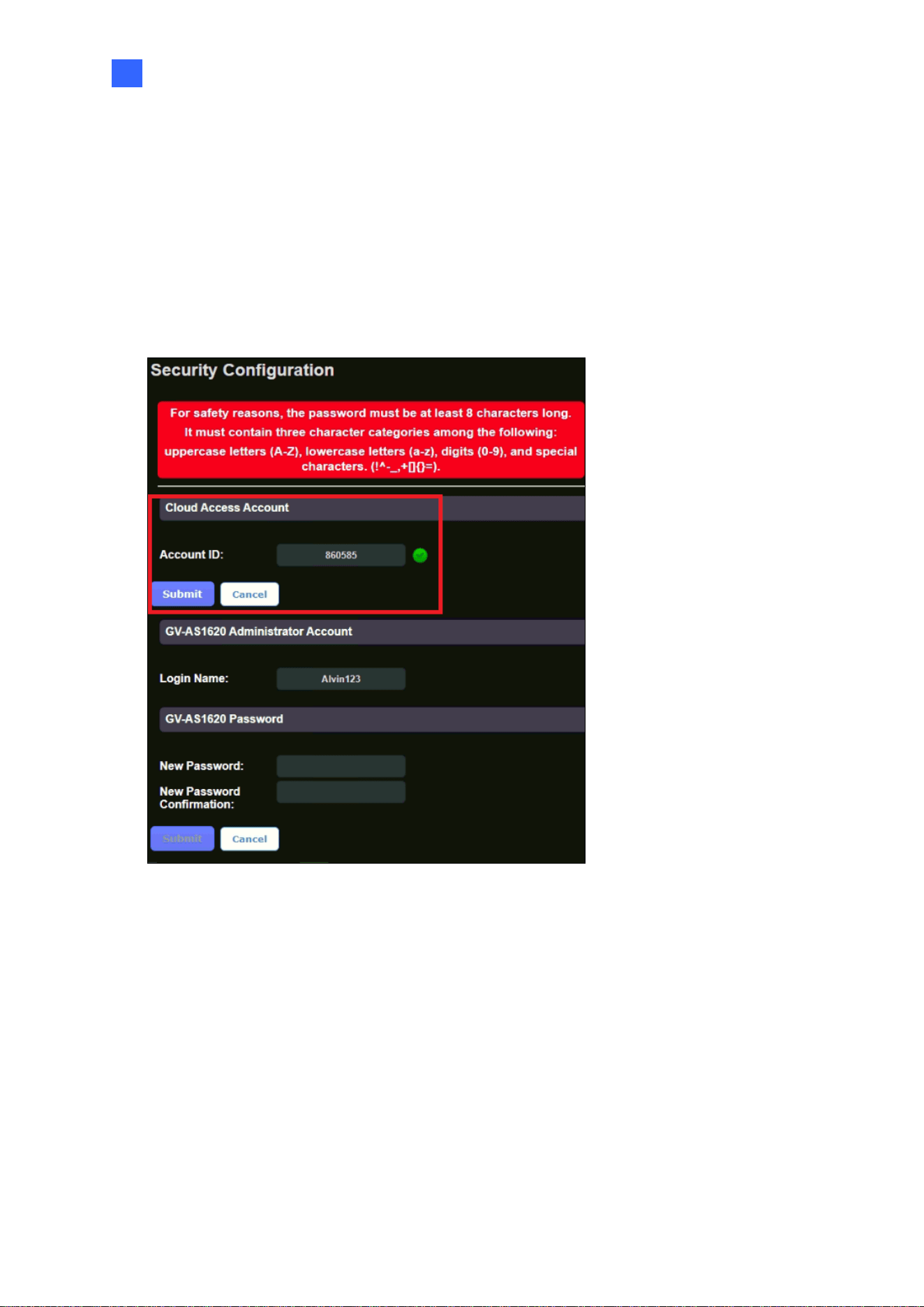
4.1.3 Security Configuration
The Security Configuration page allows GV-AS1620 to connect to GV-Cloud Access Control.
Before connecting, you must first create an account on the GV-Cloud Access Control
platform.
1. In the left menu, click Security Configuration. This page appears.
Figure 4-3
2. Type the Account ID you created on GV-Cloud.
3. Click Submit under the Cloud Access Account section.
4. Once connecting to GV-Cloud Access Control, a green status appears next to the
Account ID field.

30
After you have established the connection, add your GV-AS1620 on the GV-Cloud Access
Control’s Device List for the central access control. See 4.2.1 Adding a Device in GV-Cloud
Access Control User’s Manual.
Note:
1. The GV-AS1620 Administrator Account and GV-AS1620 Password are the login ID
and password of this Web interface.
2. If your GV-AS1620 password changes, update it on GV-Cloud Access Control to
maintain the connection.
3. To switch to a different GV-Cloud Access Control account, type the account ID in the
Cloud Access Account section and click Submit.
The Web Interface for GV-Cloud Access Control Connection
31
4
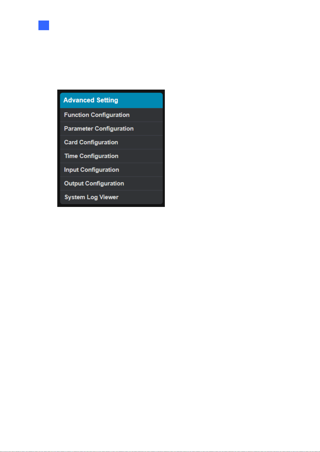
4.2 Advanced Settings
Under Advanced Settings, you can configure door settings, turn on alarms, set the device
time, edit the input / output functions, and view system logs.
Figure 4-4
32
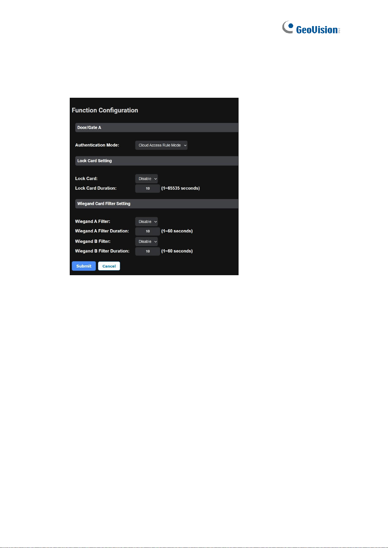
4.2.1 Function Configuration
In the left menu, click Function Configuration. This page appears.
Figure 4-5
[Door/Gate A]
◼ Authentication Mode: Select the desired access rules.
Local Unlock Mode: Select the mode to open the door / gate on GV-AS1620. The
held-open state cannot be cleared through GV-Cloud Access Control.
Local Lock Mode: Select the mode to lock the door / gate on GV-AS1620. The
locked state cannot be cleared through GV-Cloud Access Control.
Cloud Access Rule Mode: Select the mode to follow the access rules set on GV-
Cloud Access Control.
[Lock Card Setting] Enable the setting and specify the duration you want to prevent re-
access for a card
[Wiegand Card Filter Setting]
◼ Wiegand A/B Filter: Enable to avoid recording repeated access logs, from the same
card via Wiegand port A or B, within the duration set.
Wiegand A/B Filter Duration: Set the duration of filter, from 1 ~ 60 seconds.
The Web Interface for GV-Cloud Connection
33
4
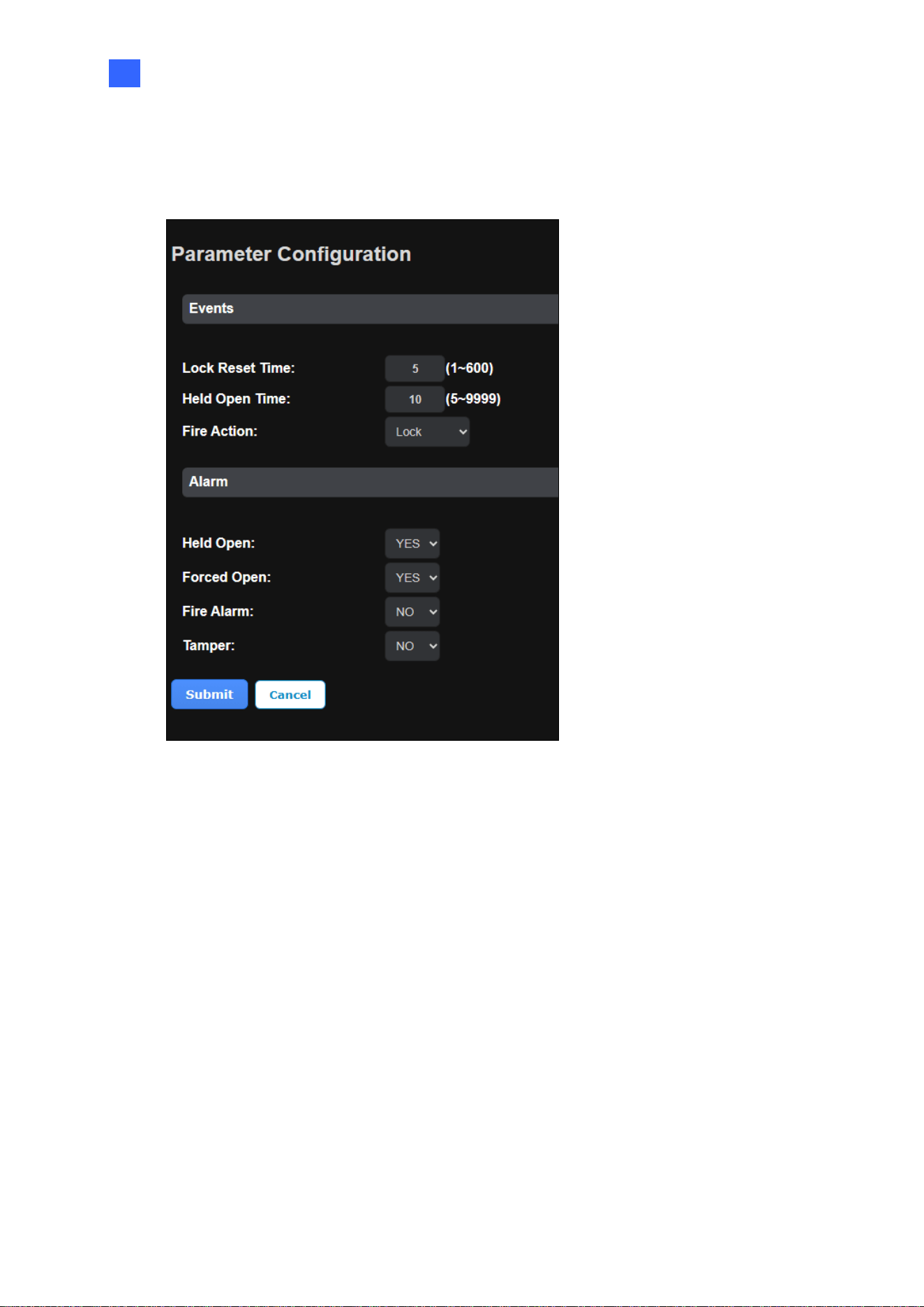
4.2.2 Parameter Configuration
In the left menu, click Parameter Configuration. This page appears.
Figure 4-6
[Events]
◼ Lock Reset Time: Sets the time (1 to 600 sec.) that a door remains open after which the
door will automatically be locked.
◼ Held Open Time: Sets the time (5 to 9999 sec.) that a door can be held open before an
alarm is generated.
◼ Fire Action: Locks or unlocks the door when a fire condition occurs. Otherwise, remain
the door’s current state by selecting Unchanged.

34
[Alarm]
◼ Held Open: This alarm activates whenever the door is held open over the specified time
period.
◼ Forced Open: This alarm activates whenever the door is opened by force.
◼ Fire Alarm: This alarm activates whenever fire is detected.
◼ Tamper: This alarm activates whenever the sensor for tampering alarm is triggered. The
tampering alarm sensor must be installed separately and the triggering conditions
depend on the type of sensor used, such as the controller’s cabinet being opened.
Note: If you have defined the alarm conditions in the Input Configuration and Output
Configuration pages, remember to activate the corresponding alarms here; otherwise, even
though the alarm conditions are met, the expected alarm will not be triggered. The default
setting for all alarms is NO.
The Web Interface for GV-Cloud Connection
35
4
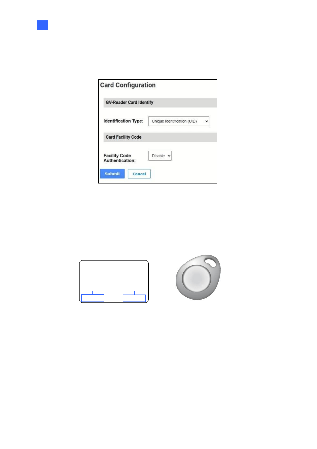
4.2.3 Card Configuration
In the left menu, click Card Configuration to set up access cards / fobs.
Figure 4-7
◼ GV-Reader Card Identify: Sets RS-485 readers on GV-AS1620 to read UID (unique
identification) or GID (GeoVision ID) from cards / fobs. To use GeoVision Identification
(GID), make sure there are two numbers on your cards / fobs as shown below. If there is
only one number on them, GID is not supported and you must select Unique
Identification (UID).
138,0857214001110
UID
GID
14001164
138
,
08572
UID
GID
Figure 4-8
◼ Card Facility Code – Facility Code Authentication: Reads the first few digital numbers
(facility code) from cards / fobs and grant access to those with the same facility code.
Take the card in Figure 4-8 as example; when it is enrolled in GV-ASManager using UID
number 138,08572, and the facility code function in enabled, any cards with the start
number 138 will have access.

36
4.2.4 Time Configuration
See 3.2.3 Time Configuration for details.
4.2.5 Input Configuration
See 3.2.4 Input Configuration for details.
4.2.6 Output Configuration
See 3.2.5 Output Configuration for details.
4.2.7 System Log Viewer
In the left menu, click System Log Viewer to view the current system status and dump data
that can be used by service personnel for analyzing problems.
The Web Interface for GV-Cloud Connection
37
4
4.3 Extended Device
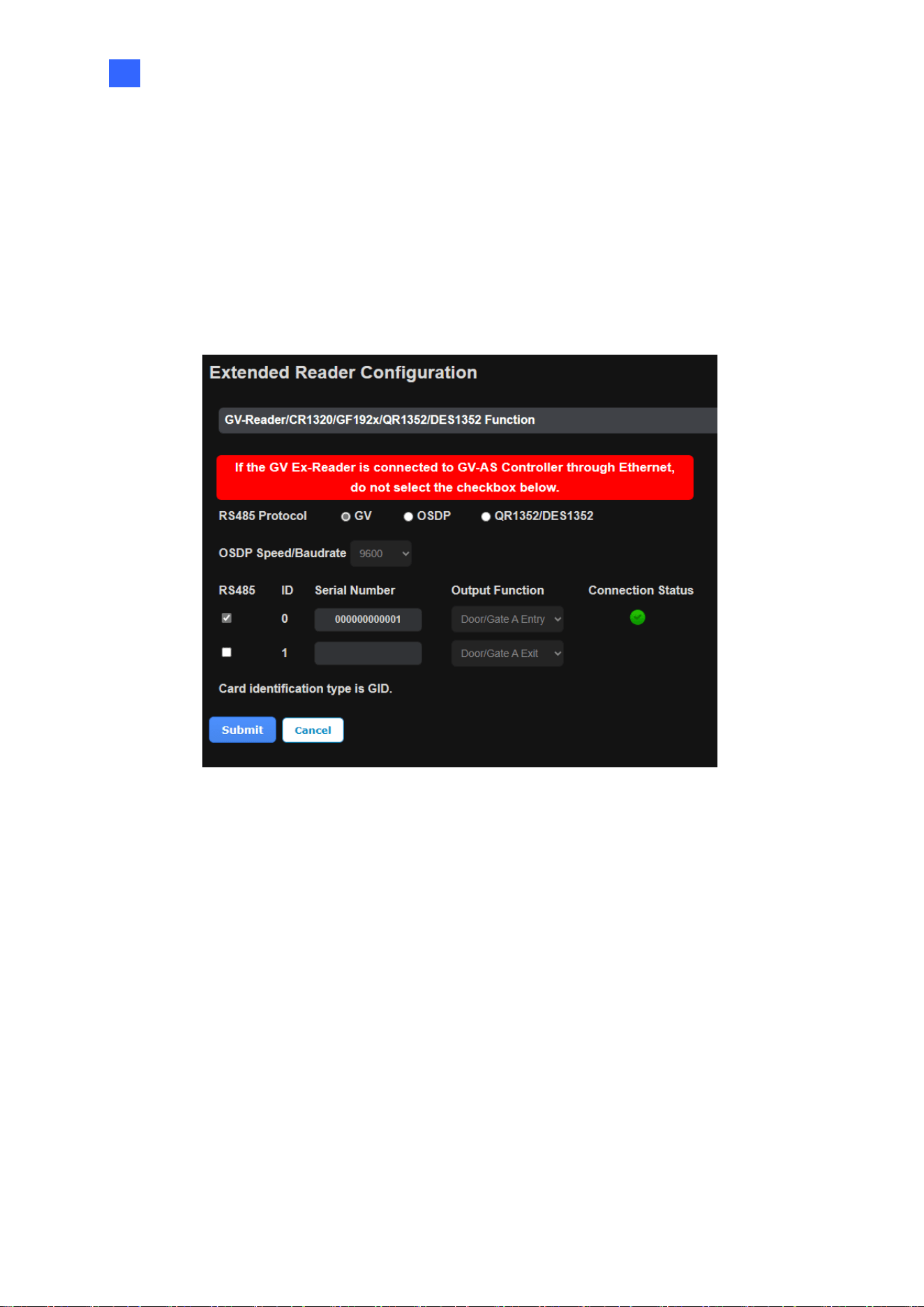
4.3.1 Extended Reader Configuration
In the left menu, click Extended Reader Configuration to define the readers connected to
the controller via RS-485 or network, and then use the Output Function dropdown list to
specify the door usage associated with the reader.
Figure 4-9
[Protocol]
◼ GV: For the following GeoVision readers, select this protocol.
GV-RK1352 / R1352 / DFR1352: Select the RS-485 checkbox and type the Serial
Number of the reader. The ID number located next to the serial number will be
assigned to the reader.
GV-Reader 1251 / Reader 1352 V2: Select the RS-485 checkbox and leave the
serial number field blank. Note that the ID number located next to the serial number
needs to match the reader’s ID number defined by the DIP switches on the reader.
GV-GF1921 / GF1922 / CR1320 / FR2020: Type the MAC address of the
fingerprint reader or the camera and do not select the RS-485 checkbox.

38
GV-CR420: Select the RS-485 checkbox only if the GV-CR420 is connected to the
controller through RS-485. If the reader is connected via network do not check the
RS485 box. Type the MAC address of GV-CR420 if you use the latest firmware.
◼ OSDP: For OSDP compliant readers, e.g. GV-RKD1352, select this protocol and select
the paired ID No. of the reader (ID #1 ~ #2).
◼ QR1352/DES1352: For GV-QR1352 / DES1352 / R1354 reader, select this protocol and
select the paired ID No. of the reader.
Click Submit. The green Connection Status indicates the successful connection between
GV-AS1620 and the reader whereas a red status indicates otherwise.
Note: When the RS-485 checkbox is not selected, the Extended Reader Configuration page
can be used to configure network readers.
The Web Interface for GV-Cloud Connection
39
4
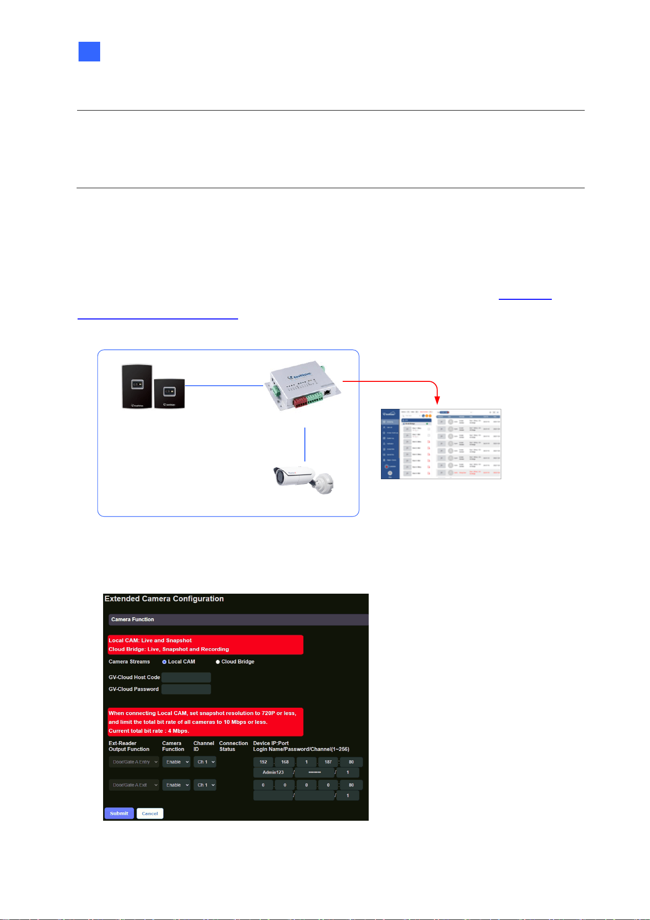
4.3.2 Extended Camera Configuration
By combining the GV-Cloud Bridge encoder with GV-AS1620, the live view, snapshots, and
recordings of IP cameras mounted around readers can be transmitted to the GV-Cloud
platform in response to access events. Alternatively, you can connect IP cameras directly to
the GV-AS1620, which will transmit live video and snapshots to the GV-Cloud platform.
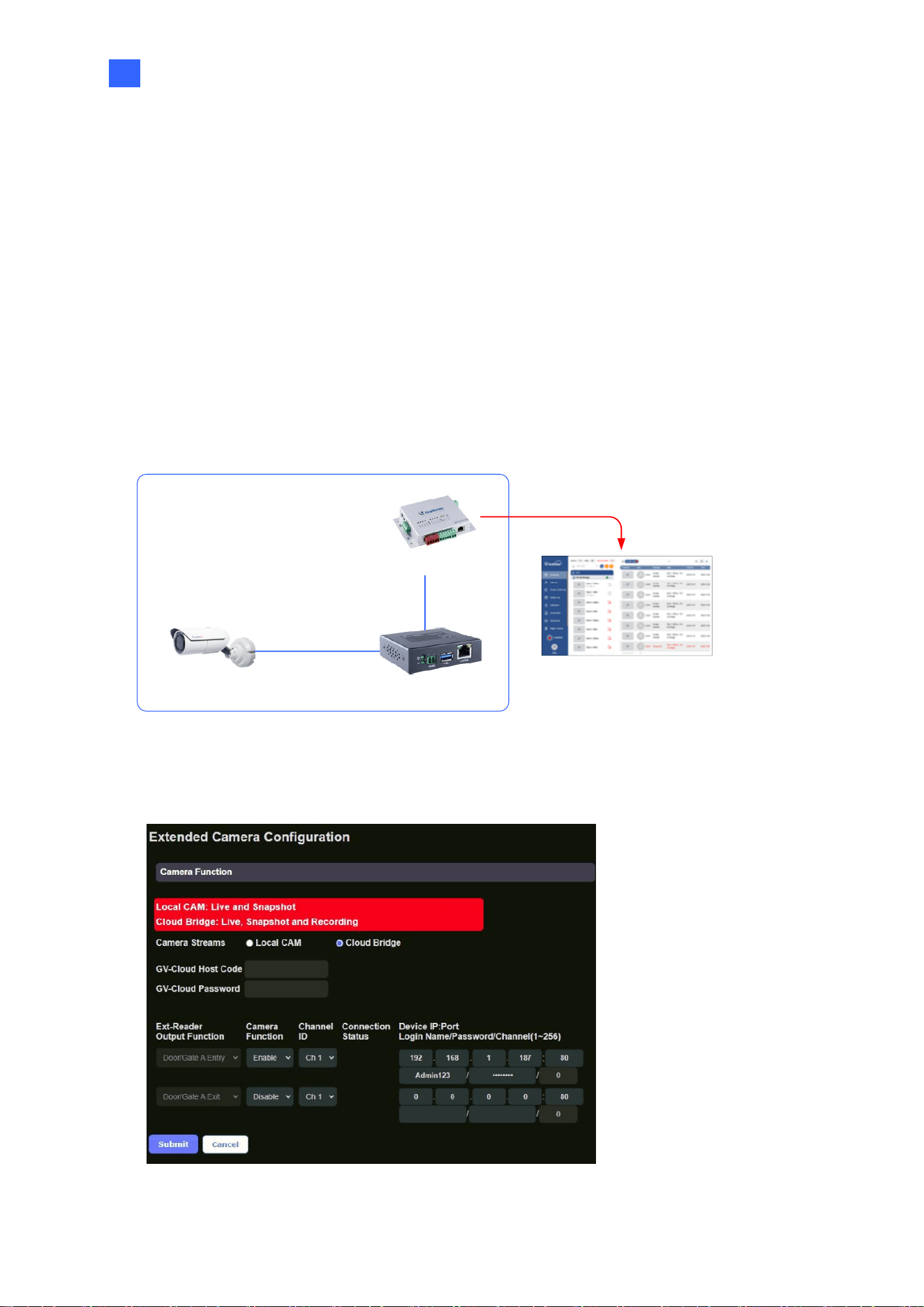
4.3.2.1 Connecting GV-Cloud Bridge to GV-AS1620
For entry and exit video monitoring, connect two IP cameras to GV-AS1620 via the GV-
Cloud Bridge encoder, as shown below.
GV-AS1620
GV-Cloud Access Control
IP Camera
GV-Cloud Bridge
Live view, Snapshots & Playback
Up to 2 CAMs
1. In the left menu of GV-AS1620’s Web interface, click Extended Camera Configuration.
This page appears.
Figure 4-10
40
2. Select Cloud Bridge from the Camera Streams options.
3. Select Enable from the Camera Function dropdown list to enable the snapshot and
live view functions of the camera from GV-Cloud Bridge.
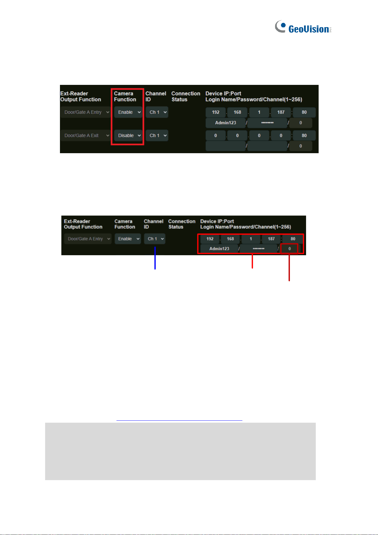
Figure 4-11
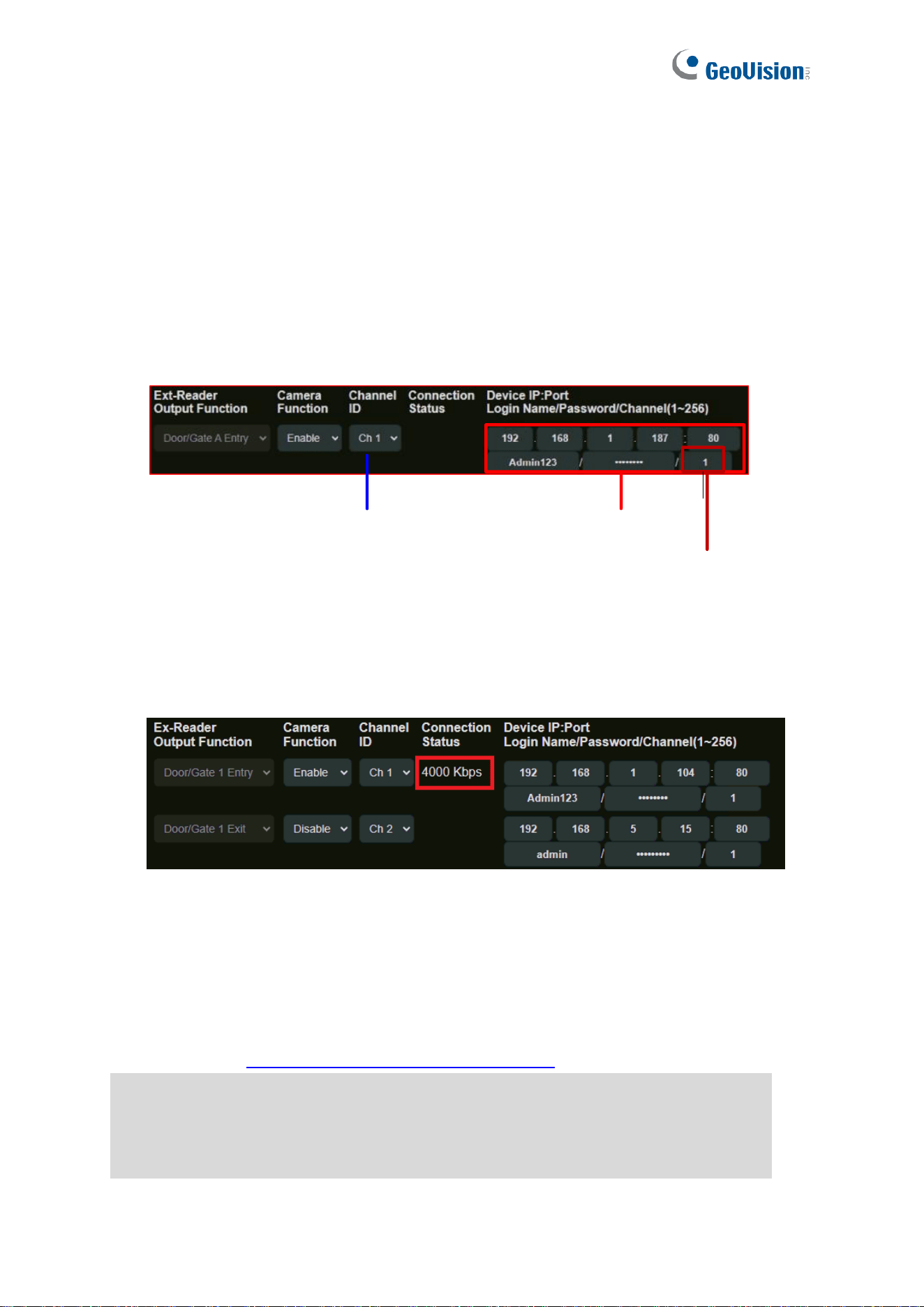
4. Select Channel ID (CH1 ~ CH4) corresponding to a camera channel from GV-Cloud
Bridge.
5. Type the GV-Cloud Bridge’s IP, ID and password to log in.
Camera's channel on GV-Cloud Bridge GV-Cloud Bridge's Login info
Void
Figure 4-12
Click Submit. The green Connection Status indicates a successful connection between GV-
AS1620 and the IP cameras from GV-Cloud Bridge, while the red status indicates an
unsuccessful connection.
[GV-Cloud Access Control Settings]
In addition to the settings described above in Connecting GV-Cloud Bridge to GV-AS1620,
the following settings must be completed in order to gain access to the GV-Cloud platform
for not only live view / snapshot but also playback. The entire settings can be found in 6.2
Accessing Playback in GV-Cloud Access Control User’s Manual.
6.2.1 Adding a Playback License
6.2.2 Creating a Host on GV-Cloud VMS
6.2.3 Configuring GV-Cloud Bridge and a Controller
6.2.4 Accessing Playback
The Web Interface for GV-Cloud Access Control Connection
41
4
4.3.2.2 Connecting IP Cameras to GV-AS1620
For entry and exit video monitoring, connect two IP cameras to the GV-Cloud platform via
GV-AS1620, as shown below. For the integration, it is required to add GV-AS1620 as a host
on the GV-Cloud platform first. See 6.1.1 Creating a Host on GV-Cloud VMS in GV-Cloud
Access Control User’s Manual.
Wiegand / RS-485 / TCP/IP
Reader
GV-AS1620
GV-Cloud Access Control
IP Camera
Live view &
Snapshots
Up to 2 CAMs
1. In the left menu of GV-AS1620’s Web interface, click Extended Camera Configuration.
This page appears.
Figure 4-13
Note:
1. The GV-Cloud Access Control License is required for accessing access control
activities, event logs, snapshots, and live view on GV-Cloud Access Control.
2. The Playback License is required for accessing recordings on the GV-Cloud platform.
42
2. Select Local CAM from the Camera Streams options.
3. Type GV-Cloud Host Code and Password created on GV-Cloud VMS.
4. On the corresponding reader’s entry, select Enable from the Camera Function
dropdown list to enable the snapshot and live view functions of the camera.
5. Select Channel ID (CH1 ~ CH2) corresponding to a camera channel displayed on GV-
Cloud VMS. Make sure not to select the same channel ID for different cameras on the
GV-AS1620.
6. Type the IP camera’s IP, ID and password to log in. If the camera has multi sensors,
type the specific channel number of the sensor.
Camera's channel on GV-Cloud VMS
Camera's Login info
Channel No. within a multi-sensor camera
Figure 4-14
7. Click Submit. Once the connection between GV-AS1620 and the IP camera is
successfully built, the bit rate of the IP camera will be displayed under the Connection
Status column.
Figure 4-15
[GV-Cloud Access Control Settings]
In addition to the settings described above in Connecting IP Cameras to GV-AS1620, the
following settings must be completed in order to gain access to the GV-Cloud platform for
live view and snapshots. The entire settings can be found in 6.1 Receiving Snapshots and
Live Streaming in GV-Cloud Access Control User’s Manual.
6.1.1 Creating a Host on GV-Cloud VMS
6.1.2 Configuring a Controller
6.1.3 Viewing Live Stream

The Web Interface for GV-Cloud Access Control Connection
43
4
Note:
1. Before connecting a local IP camera to GV-AS1620, make sure to set the camera’s
resolution to 720P or below, and limit the total bit rate of all cameras to 10 Mbps or less.
2. If a green status icon does not appear beside GV-Cloud Host Code, make sure the Host
Code and Password are consistent with those created on GV-Cloud VMS.
3. The GV-Cloud Access Control License is required for accessing access control
activities, event logs, live view, and snapshots on GV-Cloud Access Control.
44
Chapter 5 Troubleshooting
Q1: GV-ASManager cannot connect to the controller over the Internet.
The issue can be caused by a number of factors, including IP address conflict, incorrect
connection settings, and network failure. Follow the steps below to assign a fixed IP to the
GV-ASManager and the controller, respectively. This procedure can determine whether the
issue is caused by faulty devices or incorrect network settings.
1. Disconnect the hub or switch, which connects both the GV-ASManager and the controller,
from the Internet.
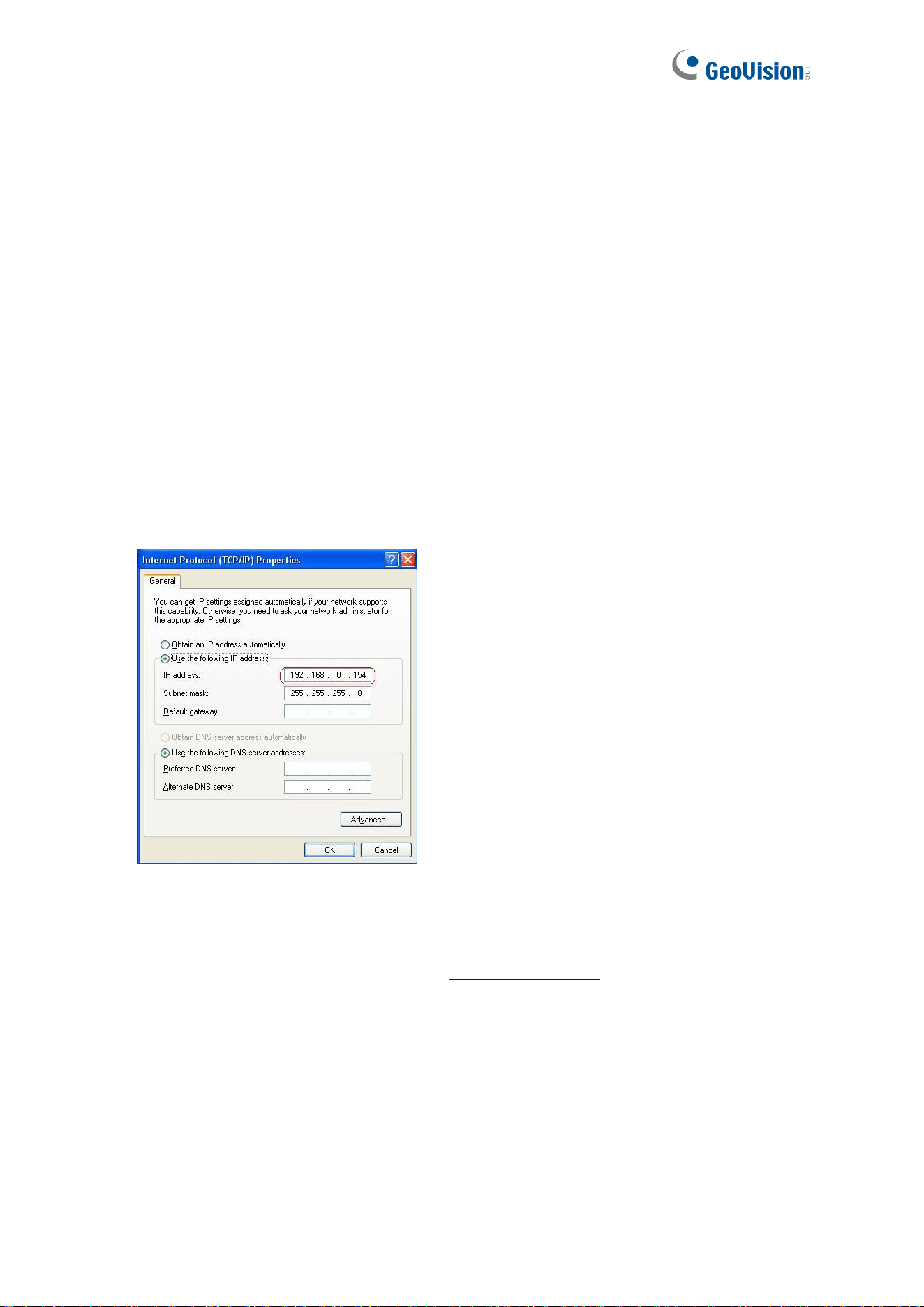
2. Give the GV-ASManager a fixed IP address that is NOT used by another device under
the LAN, e.g. 192.168.0.154.
Figure 5-1
3. Reset the controller to factory defaults. For details, see 3.1.1 System Setup.
4. Log in the controller using the default IP: http://192.168.0.100
Troubleshooting
45
5
5. In the IP address fields, give the controller an IP address that is NOT used by another
device under the LAN, e.g. 192.168.X.XXX.
Figure 5-2
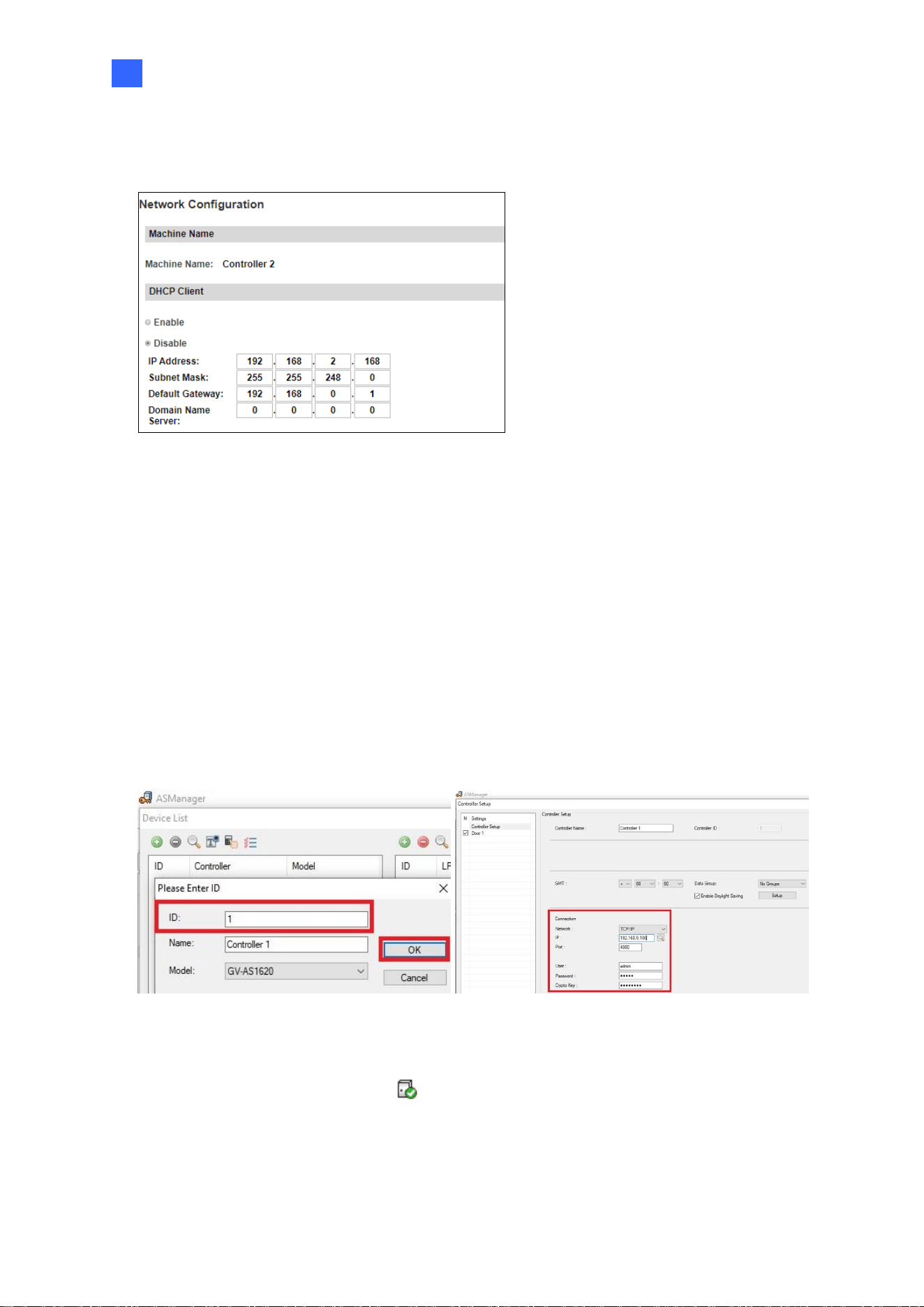
6. On the GV-ASManager, type the following settings:
Controller ID: 1
Network: TCP/IP
IP: 192.168.X.XXX
Port: 4000
User: admin
Password: admin
Crypto key: 12345678
Figure 5-3
7. The connection between the GV-ASManager and controller should be established under
the LAN, with the connection icon appearing. If disconnection occurs soon after
reconnecting the hub or switch to the Internet, it is likely due to other network issues.
Please contact your network administrator.
46
Q2: The connection established between the GV-ASManager and the controller
is interrupted.
This may be due to IP address conflict. Follow these steps to troubleshoot the problem:
1. Disconnect the hub or switch, which connects to both the GV-ASManager and the
controller, from the network.
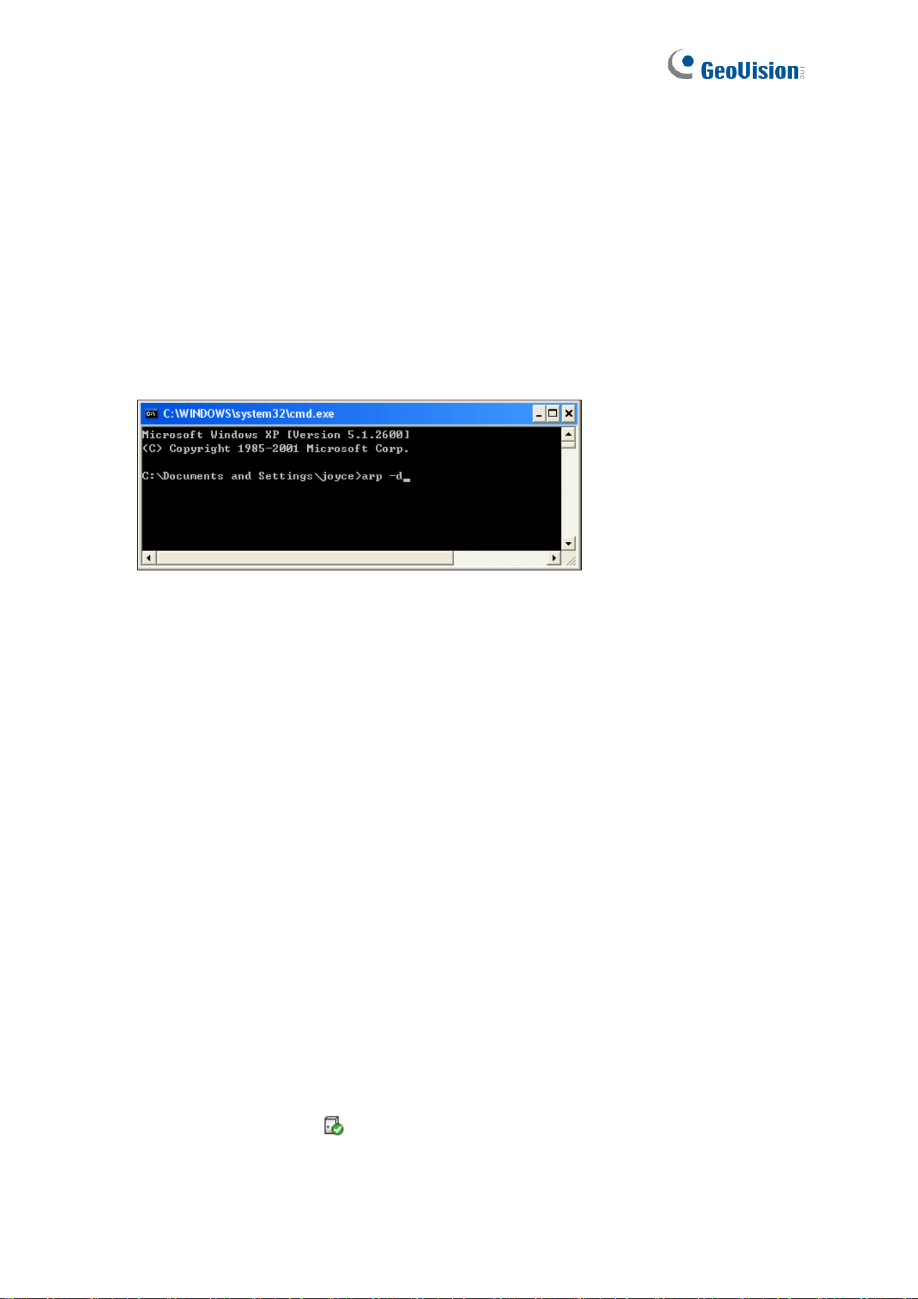
2. Run Windows Command Prompt. Take Classic Windows Start Menu for example, click
Start, select Accessories and click Command Prompt.
3. Type arp –d and press Enter.
Figure 5-4
4. Give the GV-ASManager a fixed IP address that is NOT used by another device under
the LAN. See Figure 5-1.
5. Log in the controller The Network Configuration page appears.
6. In the IP address field, give the controller an IP address that is NOT used by another
device under the LAN.
7. On the GV-ASManager, enter the following settings. See Figure 5-3.
Controller ID: 1
Network: TCP/IP
IP: 192.168.0.XXX
Port: 4000
User: admin
Password: admin
Crypto key: 12345678
8. The connection between the GV-ASManager and the controller should be established
with the connection icon appearing. If disconnection happens soon after you connect
the hub or switch back to the network, then it should be other network problems. Please
contact your network administrator.

Troubleshooting
47
5
Q3: GV-ASManager cannot receive card messages but the reader accepts the
card when the connection between the GV-ASManager and GV-AS1620 is well
established.
It may be due to memory failure in the controller. Reset the controller module to factory
settings. For details, see 3.1.1 System Setup.
Q4: After I added a card on GV-ASManager and then presented it to the reader,
the message “Access Denied Invalid Card” still appears.
It may be the card format is not compatible with the controller. Make sure the card format is
64 bits. Otherwise, send us the related information of your card format so that we can
customize the setting for you.
Q5: GV-ASManager cannot receive card messages from the reader connected
to the controller through RS-485 interface.
1. Make sure the reader is correctly wiring to the controller.
2. Make sure the reader has been defined on the controller. See 3.3 Extended Device for
details.
Q6: How can I find more help?
Visit our website at http://www.geovision.com.tw/products.php?c1=25
Write to us at support@geovision.com.tw
