3x
2x
3x
4x
4x
103
37
38
z
z
z
z
z
z
z
z
z
z
102
2 3 19 20 33 43 45 47 48 49 58 59 62 97
65 67 73 74 76 80 83 88 90 91 95 96 98 100
z
100
19
20
z
101
56
83
18
7
31
90
16
3 23
67 82
18
7
MILWAUKEE ELECTRIC TOOL CORPORATION
13135 W. LISBON RD., BROOKFIELD, WI 53005
Drwg. 6
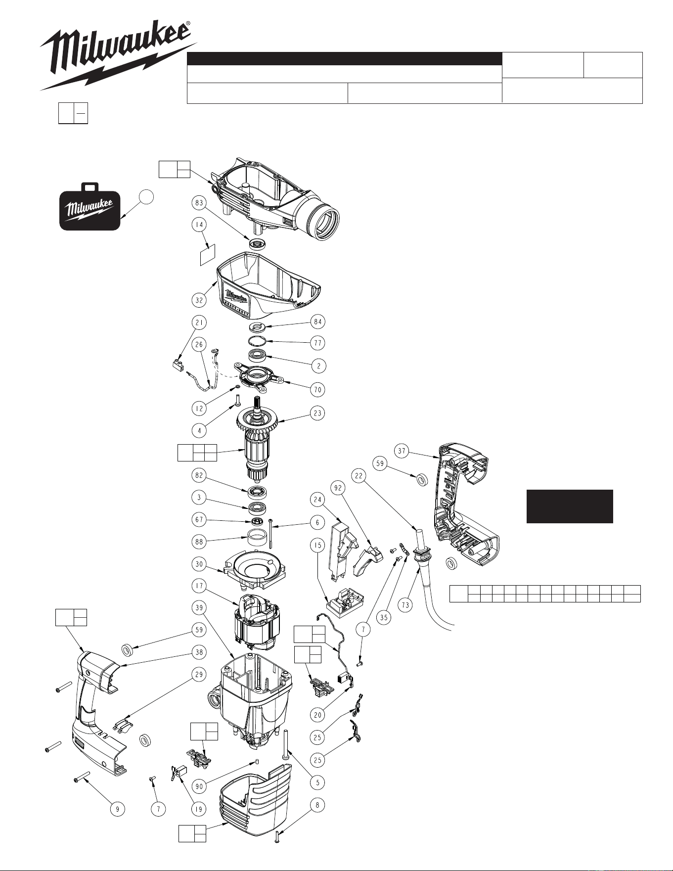
FIG. PART NO. DESCRIPTION OF PART NO. REQ.
2 02-04-0140 Ball Bearing (1)
3 02-04-0150 Ball Bearing (1)
4 05-74-0060 M5 x 20 Taptite T-25 Screw (3)
5 05-74-0070 M6 x 60 Taptite T-30 Screw (4)
6 05-74-0240 M4 x 64 Plastite T-20 Screw (2)
7 05-74-0250 M9 x 9.5 T-15 Screw (4)
8 05-74-0270 H-K4 x 22 T-15 Screw (4)
9 05-74-0280 M5 x 35 T-20 Screw (3)
12 05-90-0190 M5 Spring Washer (1)
14 12-20-5400 Service Nameplate Kit (1)
15 14-20-0340 PC Board (1)
16 16-50-0120 Service Armature Assembly (1)
17 18-50-0120 Service Field Assembly (1)
18 22-20-0050 Brush Holder Assembly (2)
19 --------------- Carbon Brush Assembly (1)
20 --------------- Carbon Brush Assembly (2 wire) (1)
21 22-56-0010 Terminal Block (1)
22 22-64-0880 Power Cord (1)
23 22-84-0010 Fan (1)
24 23-66-0033 Switch (1)
25 23-94-0110 Wire Harness (2)
26 23-94-0430 Grounding Wire Harness (1)
27 23-94-0018 Jumper Wire (See Bulletin 58-01-5400) (1)
29 31-01-0090 Light Pipe (2)
30 31-05-0140 Fan Baffl e (1)
31 31-12-0070 Motor Cap (1)
32 31-12-0260 Shroud (1)
35 31-17-0290 Cord Clamp (1)
37 --------------- Handle Halve-Left (1)
38 --------------- Handle Halve-Right (1)
39 31-50-0100 Motor Housing (1)
FIG. PART NO. DESCRIPTION OF PART NO. REQ.
59 42-42-0031 Bushing (4)
67 44-26-0090 Magnetic Disc (1)
70 44-66-0220 Bearing End Plate (1)
73 44-76-0320 Cord Protector (1)
77 44-90-0080 Internal Retaining Ring (1)
82 45-06-0020 Dust Seal (1)
83 45-06-0030 Armature Seal (1)
84 45-06-0120 Seal Ring-Left Hand Thread (1)
88 45-22-0110 Rubber Sleeve (1)
90 45-30-0055 Rubber Plug (1)
92 45-72-0020 Trigger (1)
100 14-46-0275 Brush Service Kit (1)
101 14-46-0355 Gearcase Service Kit (1)
102 14-46-0290 Maintenance Service Kit (1)
103 14-46-0215 Handle Service Kit (1)
106 42-55-0190 Accessory Carrying Case (1)
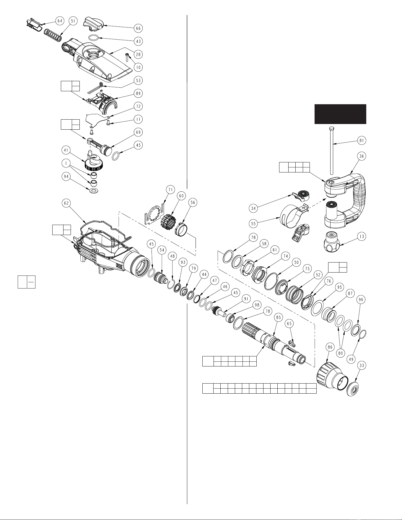
14 lb. (6,4 kg) SDS-MAX DEMOLITION HAMMER
5446-21
58-01-5400
54-24-5440
B39A
REVISED BULLETIN
SERVICE PARTS LIST
SPECIFY CATALOG NO. AND SERIAL NO. WHEN ORDERING PARTS
STARTING
SERIAL NO.
CATALOG NO.
WIRING INSTRUCTION
BULLETIN NO.
EXAMPLE:
Component Parts (Small #) Are Included
When Ordering The Assembly (Large #).
0
00
DATE
Sept. 2014
Component of #102
Maintenance Service Kit
No. 14-46-0260
=
SEE PAGE 3 FOR
LUBRICATION AND
SERVICE NOTES
106
Left Hand
Thread
6x
104
53
89
105
45
69
99
13 34 36
55 81
z
z
z
z
z
z
z
z
z
z
z
z
z
z
z
z
z
102
2 3 19 20 33 43 45 47 48 49 58 59 62 97
65 67 73 74 76 80 83 88 90 91 95 96 98 100
z
44 45 46 47 48 54
79 85 91 93 98
107
z
101
56
83
68
75
76
FIG. PART NO. DESCRIPTION OF PART NO. REQ.
68 44-86-0300 Retaining Ring Service Kit (1)
69 44-62-0010 Piston Assembly (1)
71 44-66-0370 Locking Plate (1)
72 44-66-0420 Latch Plate (1)
74 44-86-0020 Seal Retainer (1)
75 --------------- Retaining Ring Key (1)
76 --------------- Retaining Ring Key (1)
78 44-90-0301 Spindle Ring (2)
79 44-90-0440 Seal (1)
80 44-90-0510 Seal (2)
81 05-74-0055 M8 x 170mm Hex Hd. Handle Screw (1)
85 45-22-0020 Spindle Sleeve (1)
86 45-22-0030 Sleeve (1)
FIG. PART NO. DESCRIPTION OF PART NO. REQ.
87 45-22-0040 SDS Sleeve (1)
89 45-24-0060 Drive Selector Slide (1)
91 45-56-0010 Striker (1)
93 45-88-0960 Cushion Washer (1)
94 45-88-1000 Washer (1)
95 45-88-1120 Washer (1)
96 45-88-1490 Washer (1)
98 45-88-1570 Stop Washer (1)
99 14-46-0295 Handle Service Kit (1)
101 14-46-0355 Gearcase Service Kit (1)
102 14-46-0290 Maintenance Service Kit (1)
104 14-46-0285 Drive Selector Service Kit (1)
105 14-46-0345 Piston Service Kit (1)
107 45-22-0025 Spindle Sleeve Service Kit (1)
49-08-4255 Type 'Q' Grease, 45gm (1.5 oz) Tube (3)
FIG. PART NO. DESCRIPTION OF PART NO. REQ.
1 02-04-0120 Needle Bearing (2)
10 05-74-0310 M5 x 25 Taptite T-25 Screw (6)
11 05-74-0320 M5 x 12 PE T-20 Grade 8.8 Screw (2)
13 43-98-0025 Auxiliary Handle Knob (1)
28 28-20-0030 Gearcase Cover (1)
33 31-12-0420 Rubber Cap (1)
34 31-44-0165 Auxiliary Handle Detent (2)
36 31-44-0085 Auxiliary Handle (1)
41 32-65-0010 Crank Gear (1)
43 34-40-0020 O-Ring (1)
44 34-40-0085 O-Ring (1)
45 34-40-0170 O-Ring (3)
46 34-40-0175 O-Ring (1)
47 34-60-0040 Core Lifter Ring (1)
48 34-60-0090 Internal Snap Ring (1)
49 34-60-0110 Internal Snap Ring (1)
50 34-80-0010 Internal Retaining Ring (1)
51 40-50-0610 Pressure Spring (1)
52 40-50-0620 Barrel Spring (1)
53 --------------- Drive Selector Spring (1)
54 42-06-0010 Ram (1)
55 42-68-0045 Auxiliary Handle Clamp (1)
56 42-24-0010 Sleeve Bearing (1)
58 42-38-0410 Dampening Bumper (1)
60 42-76-0020 Idle Collar (1)
61 42-76-0030 Thrust Collar (1)
62 43-44-0120 Gearcase Gasket (1)
64 43-56-0100 Spring Guide (1)
65 43-96-0010 Interlock (2)
66 44-10-0190 Drive Selector Lever (1)
EXAMPLE:
Component Parts (Small #) Are Included
When Ordering The Assembly (Large #).
0
00
Component of #102
Maintenance Service Kit
No. 14-46-0260
=
SEE PAGE 3 FOR
LUBRICATION AND
SERVICE NOTES
40 g / (1.2 oz.)
80 g / (3.0 oz.)
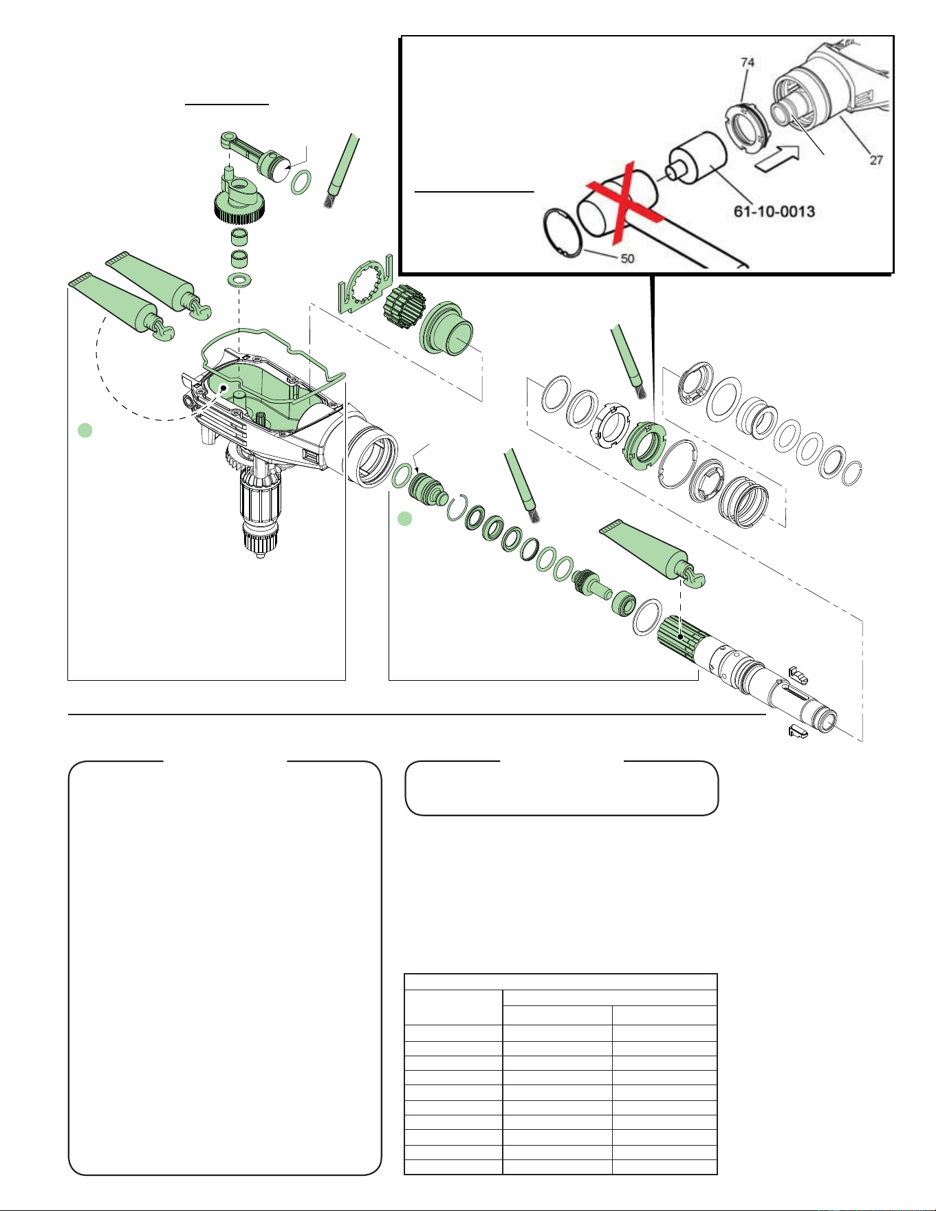
Prior to reinstalling,
clean gear assemblies
with a clean, dry cloth.
Lightly coat all parts shown
above with ‘Q’ grease.
Be sure to fill the rear piston
cavity with grease.
NOTE: The front face of the
piston is to be free of lubricant.
Place balance (approx. 80 grams, 3.0 oz.)
of the two tubes of grease in the gear cavity
of the gearcase.
Prior to
reinstalling,
lightly coat all parts
shown above with ‘Q’
grease. NOTE: The rear
face of the ram is to be free of
lubricant. Place balance of the third
tube of grease (approx. 40 grams, 1.2 oz.)
liberally around splines of the spindle sleeve.
No lubricant
on front face
No lubricant
on rear face
14-46-0290 MAINTENANCE SERVICE KIT
THIS KIT CONTAINS:
1 02-04-0140 Ball Bearing
1 02-04-0150 Ball Bearing
1 31-12-0420 Rubber Cap
1 34-40-0020 O-Ring
3 34-40-0170 O-Ring
1 34-60-0040 Core Lifter Ring
1 34-60-0090 Internal Snap Ring
1 34-60-0110 Internal Snap Ring
1 42-38-0410 Dampening Bumper
4 42-42-0031 Bushing
1 43-44-0120 Gearcase Gasket
2 43-96-0010 Interlock
1 44-26-0090 Magnetic Disc
1 44-76-0320 Cord Protector
1 44-86-0020 Seal Retainer
1 --------------- Retaining Ring Key
2 44-90-0510 Seal
1 45-06-0030 Armature Seal
1 45-22-0110 Rubber Sleeve
1 45-30-0055 Rubber Plug
1 45-56-0010 Striker
1 45-88-1120 Washer
1 45-88-1490 Washer
1 45-88-1550 Washer (5426-21 Only)
1 45-88-1570 Stop Washer
1 14-46-0275 Brush Svc. Kit (Incl. 19 & 20)
3 49-08-4255 'Q' Grease (45g/1.5 oz. tube)
14-46-0275 BRUSH SERVICE KIT
THIS KIT CONTAINS:
1 --------------- Carbon Brush Assembly
1 --------------- Carbon Brush Assembly
(Two Wire)
FASTENER TORQUE SPECIFICATIONS (FT./LBS.)
SEATING TORQUE
FIG. NO. MINIMUM MAXIMUM
2 4.43
4 3.30
5 4.43
6 0.96
7 1.25
8
9 1.25
10 3.30
11 3.30
81 1.25
LUBRICATION
No. 49-08-4255 Type 'Q' Grease
45gm (1.5 oz) Tube - 3 tubes needed
Lightly grease the O.D. of the seal retainer (74).
Insert the seal retainer into the gearcase (27), onto
the spindle sleeve (85) until the outside face of the
seal retainer is flush with the face of the gearcase.
Place the open end of the service fixture 61-10-0013
over the spindle sleeve and gently push the
retainer into the gearcase prior to installing
the retaining ring (50). Striking the
service fixture with a hammer
is not recommended,
doing so may cause
the seal retainer to
wedge in the
gearcase.
85