SKU: #XXXXXX
Model: #SW22008 GD
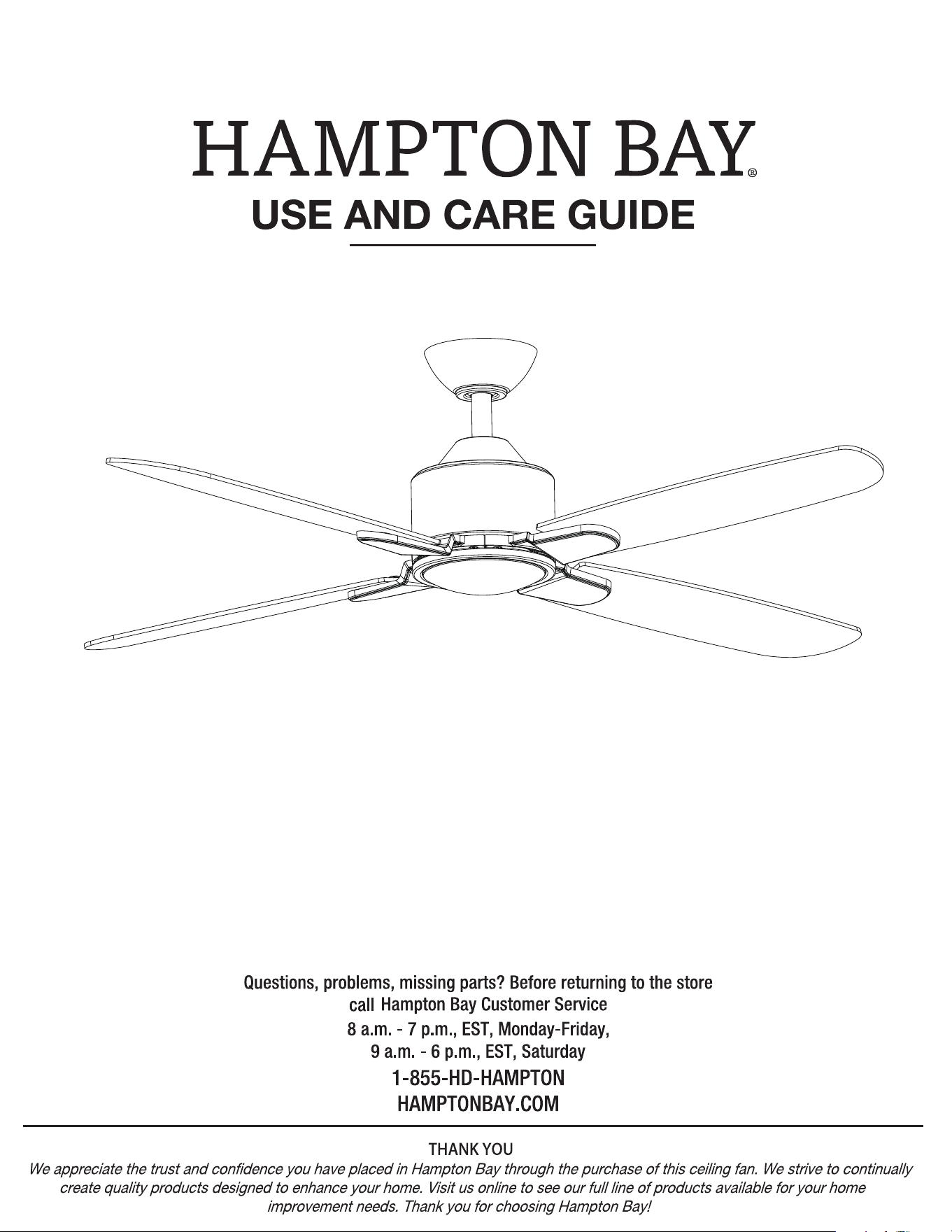
CHELIA LED 56 INCH CEILING FAN
20
21
22
SW-
1167RYS-06
Summer Wind International Ltd.
or, at our option,
gives
xx kg
(xx lb)
xxx'
xxxx xxxx xxxx
xxxx xxxx xxxx
xxxx xxxx xxxx
xx kg
(xx lb)
56 in.
(1.42 m)
12
8
1 set
1 set
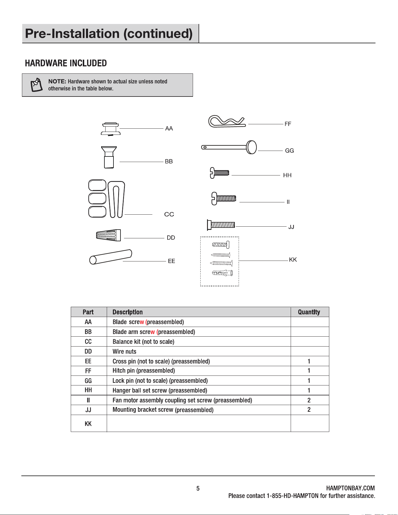
Remote control cradle hardware pack (ST3.5*13mm screw -2pcs,
ST3.0*18mm screw-2pcs, #6/32*13mm screw-2pcs, anchor -2pcs)
3+1 spare
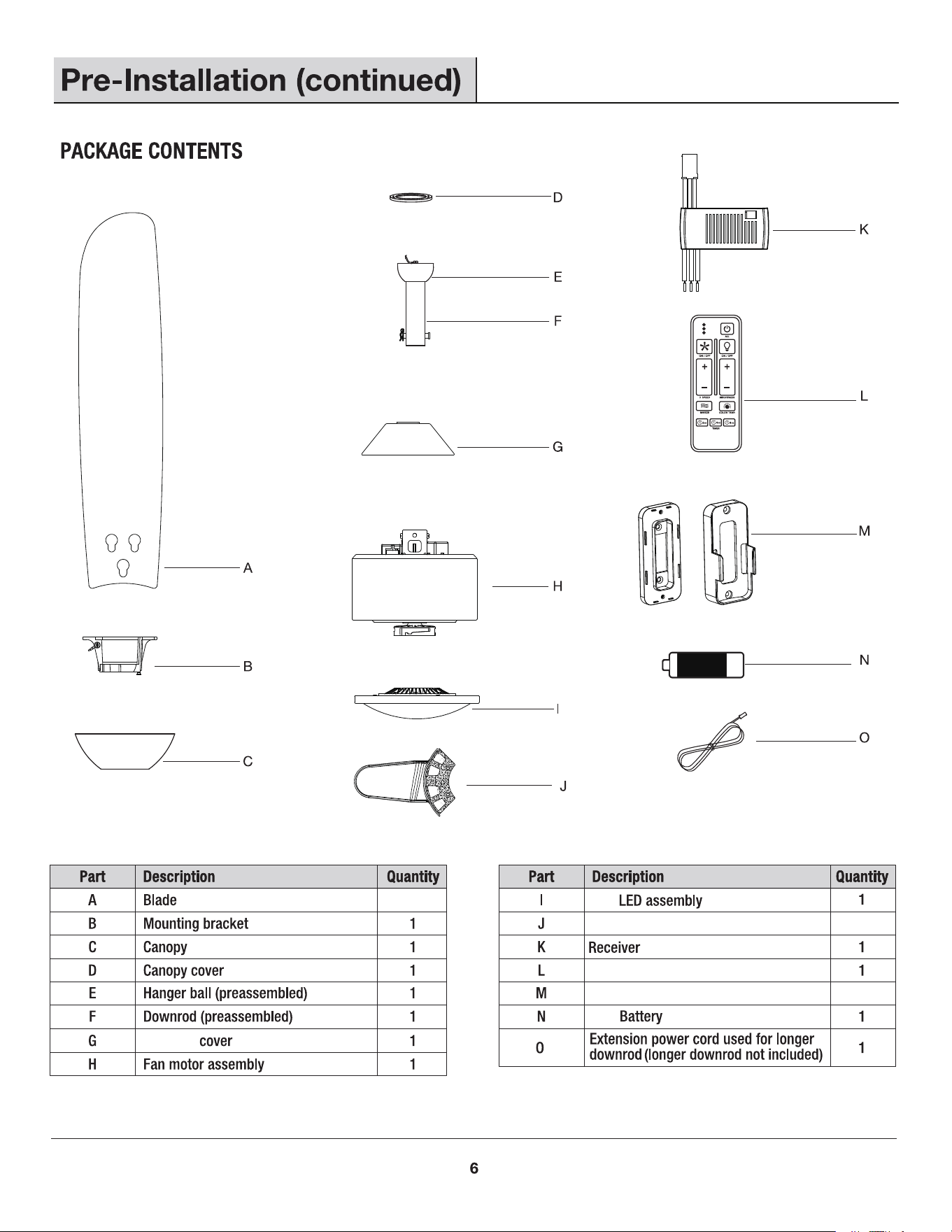
1.5V
18W
1.5V
4
Remote control
2
Remote control cradle
Blade arm
4
Coupling

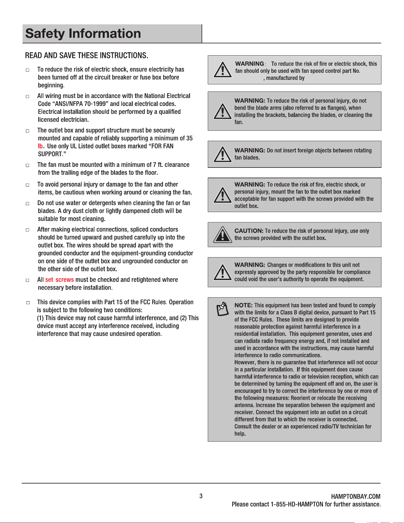
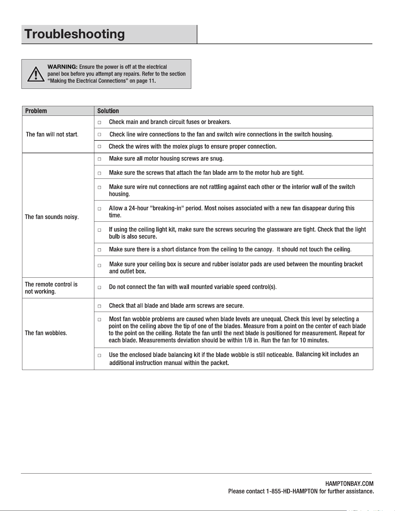
UL Listed
fuse
electrical
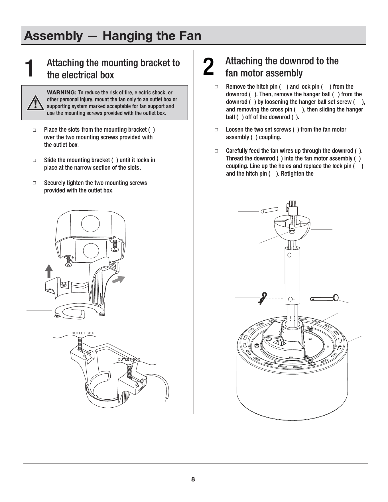
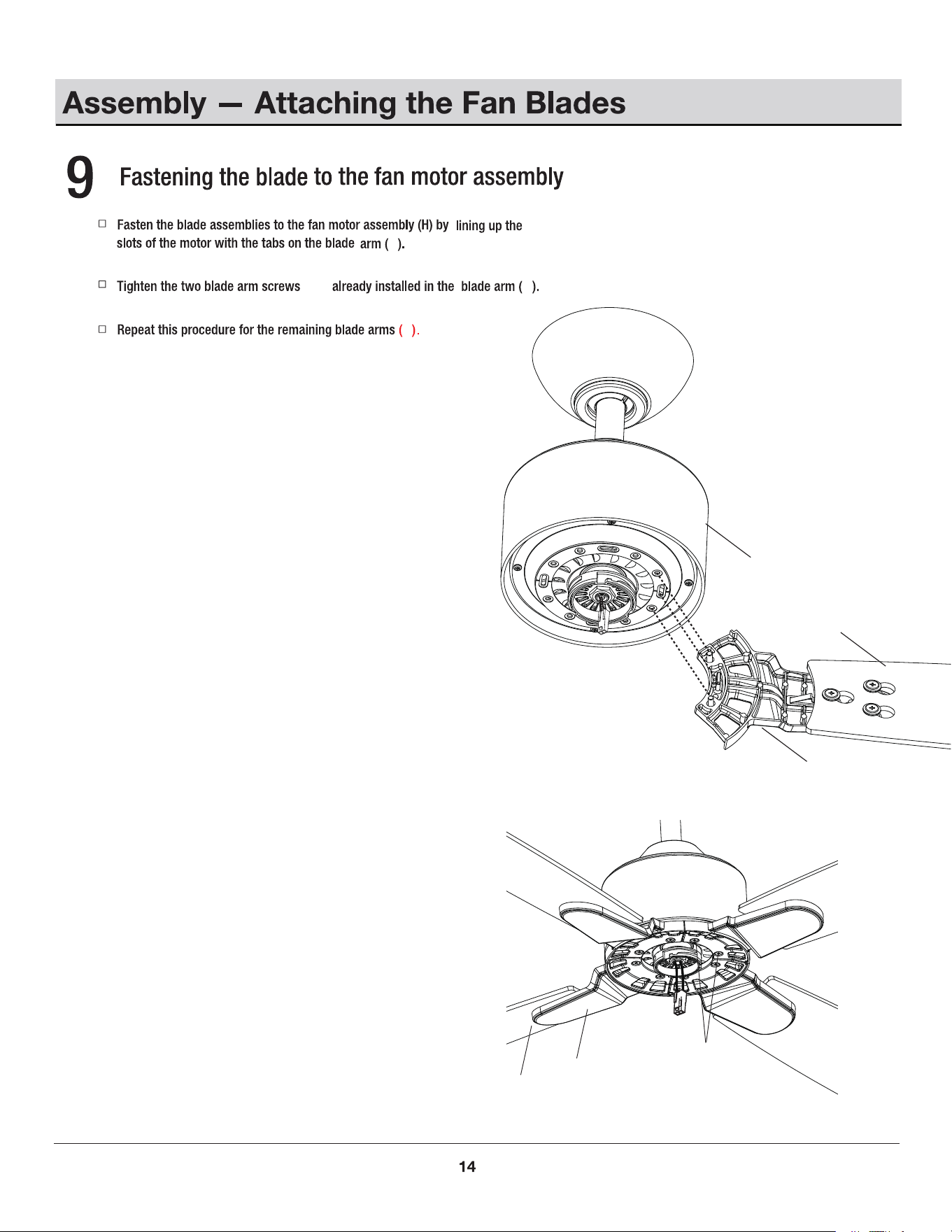
fan motor assembly
coupling set screws (II).
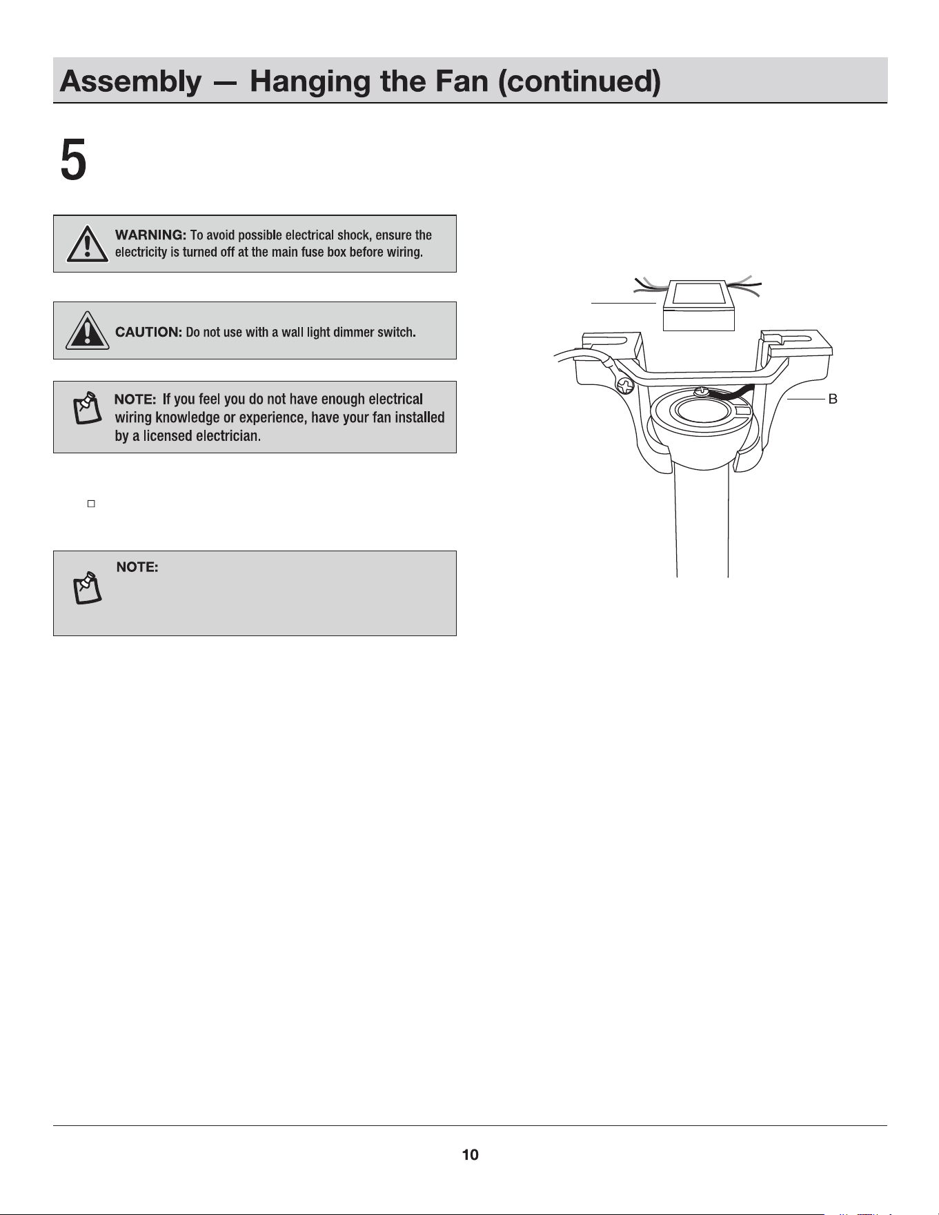
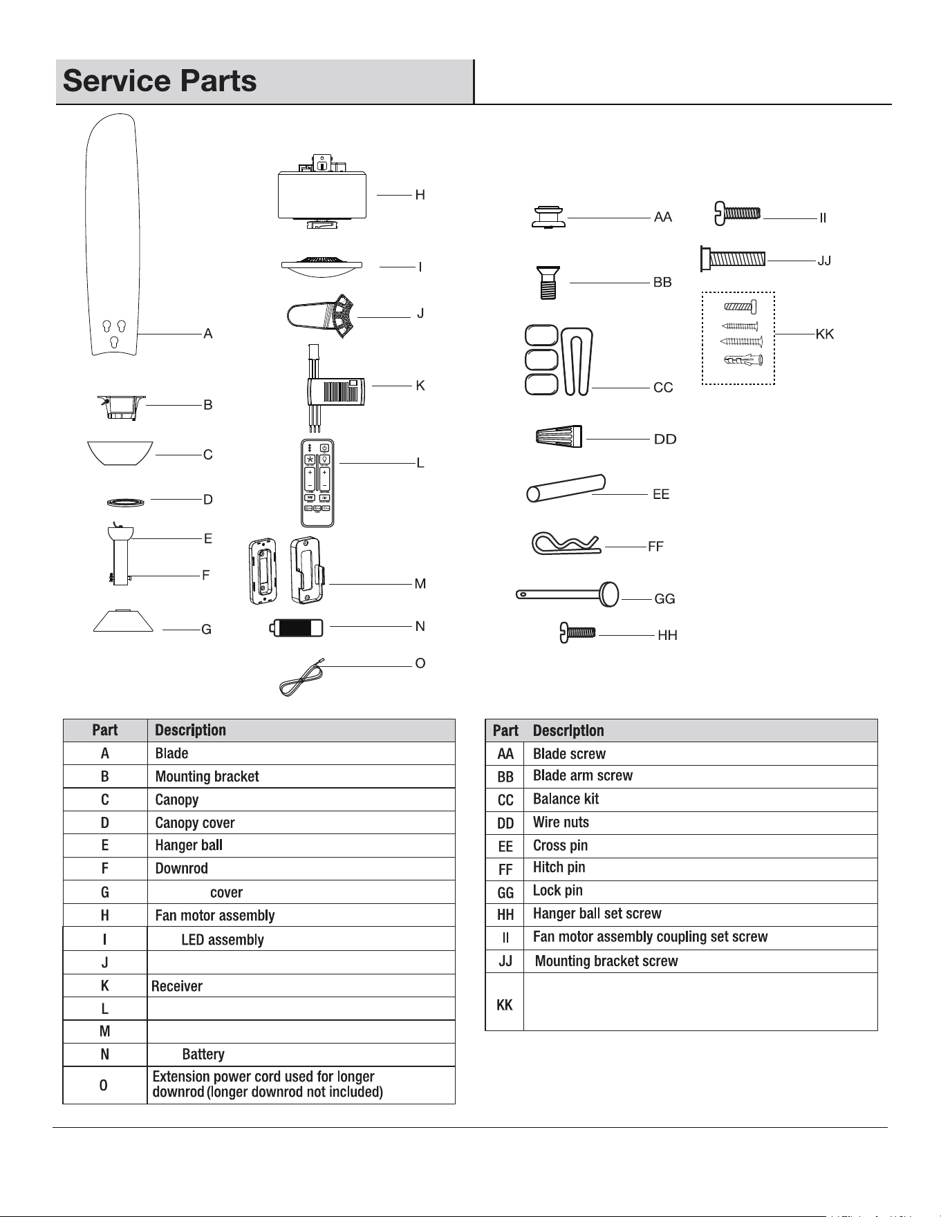
B
HH
H
B
B
EE
E
HH
F
GG
FF
II
H
FF
F
E
F
F
F
GG
FF
EE
E F
II
H
GG
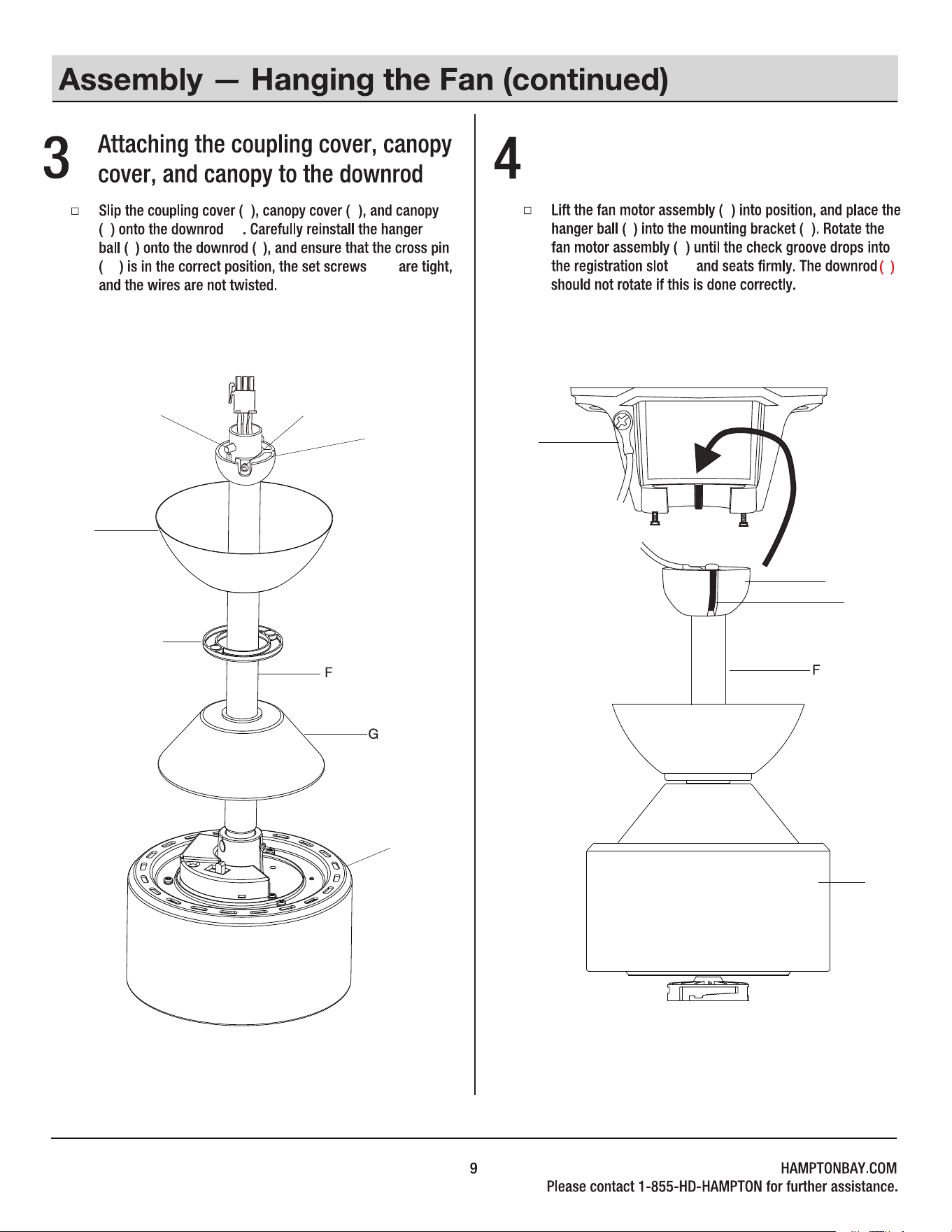
D
C
G
B
H
H
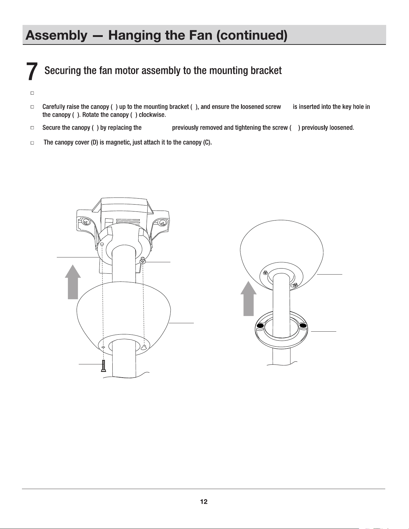
Hanging the fan motor assembly
to the mounting bracket
LL
B
EE
EE
HH
(HH)
E
E
C
(F)
F
E
E
(LL)
F
H
H
D
Insert the receiver (K) into the mounting bracket (B) with the
ventilated side facing down.
Wires coming from the downrod and the wires
coming from the power source need to be positioned on
the same side when inserting the receiver through the
mounting bracket.
K
Installing the receiver
K
H
DD
K
DD
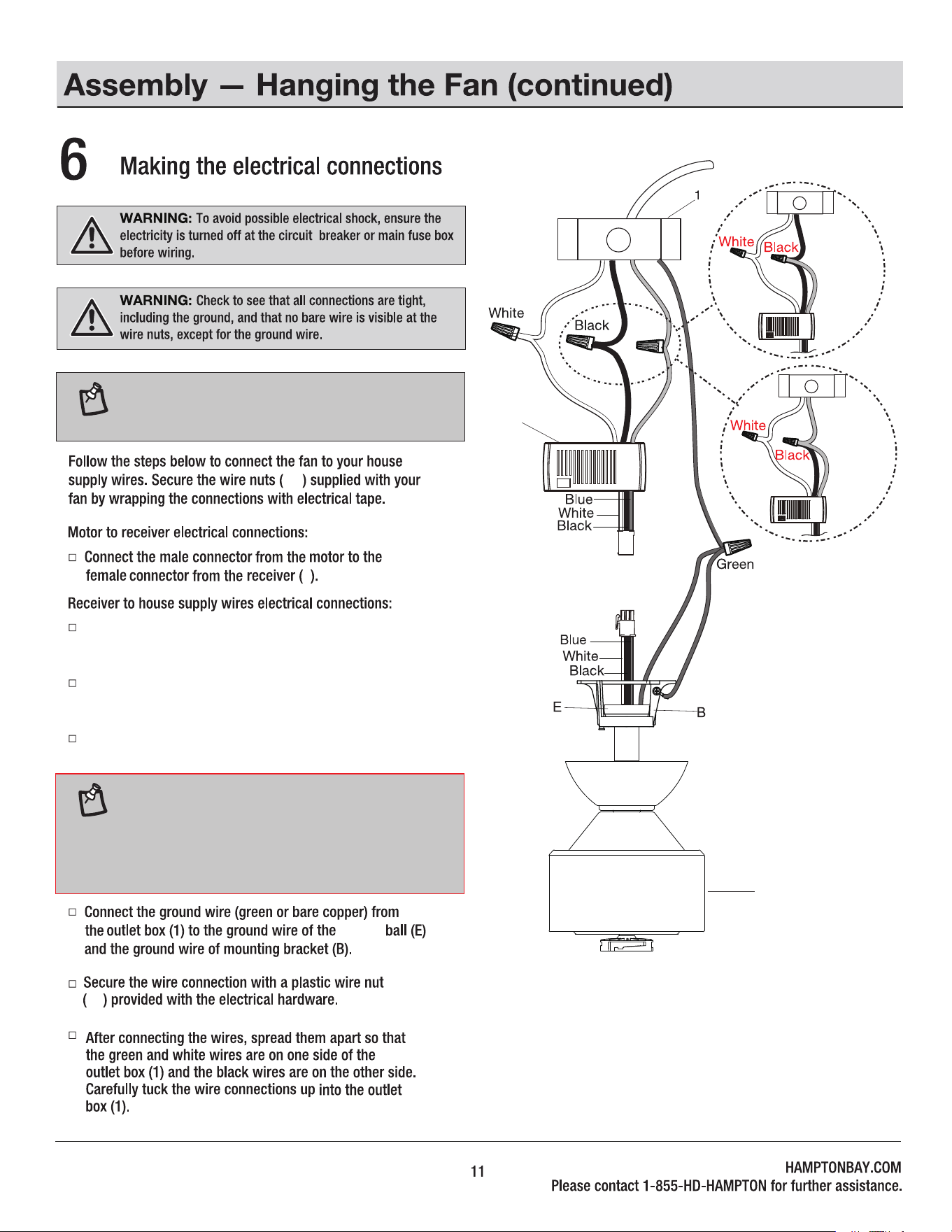
Connect the white (neutral) wire from the ceiling to
the white wire marked "AC IN N" from the receiver (K).
Connect the black (hot) wire from the ceiling to the black
wire marked "AC IN L FOR MOTOR SWITCH" from the receiver (K).
Connect the red wire from ceiling to the red wire marked
"AC IN L FOR LIGHT SWITCH" from the receiver (K).
Red
NOTE: The 3-wire receiver will enable independent
control of fan and light at the wall switch if house wiring
has separate household red and black power wires.
Optional
Optional
Red
Red
hanger
NOTE: If supply wires coming out of the ceiling only have
one red or black (hot) wire, please connect both black and
red wires from the receiver (K) to the one hot wire from
the outlet box (1). Red wire may be a different color
depending on your location. Always consult a qualified
electrician if you are unsure.
(JJ)
JJ
B
C
C
C
C
JJ
B
C
C
JJ
D
Remove one screw (JJ) from the mounting bracket (B) and loosen the other screw (JJ) approximately 1/4 turn.
screw (JJ)
MM
J
J
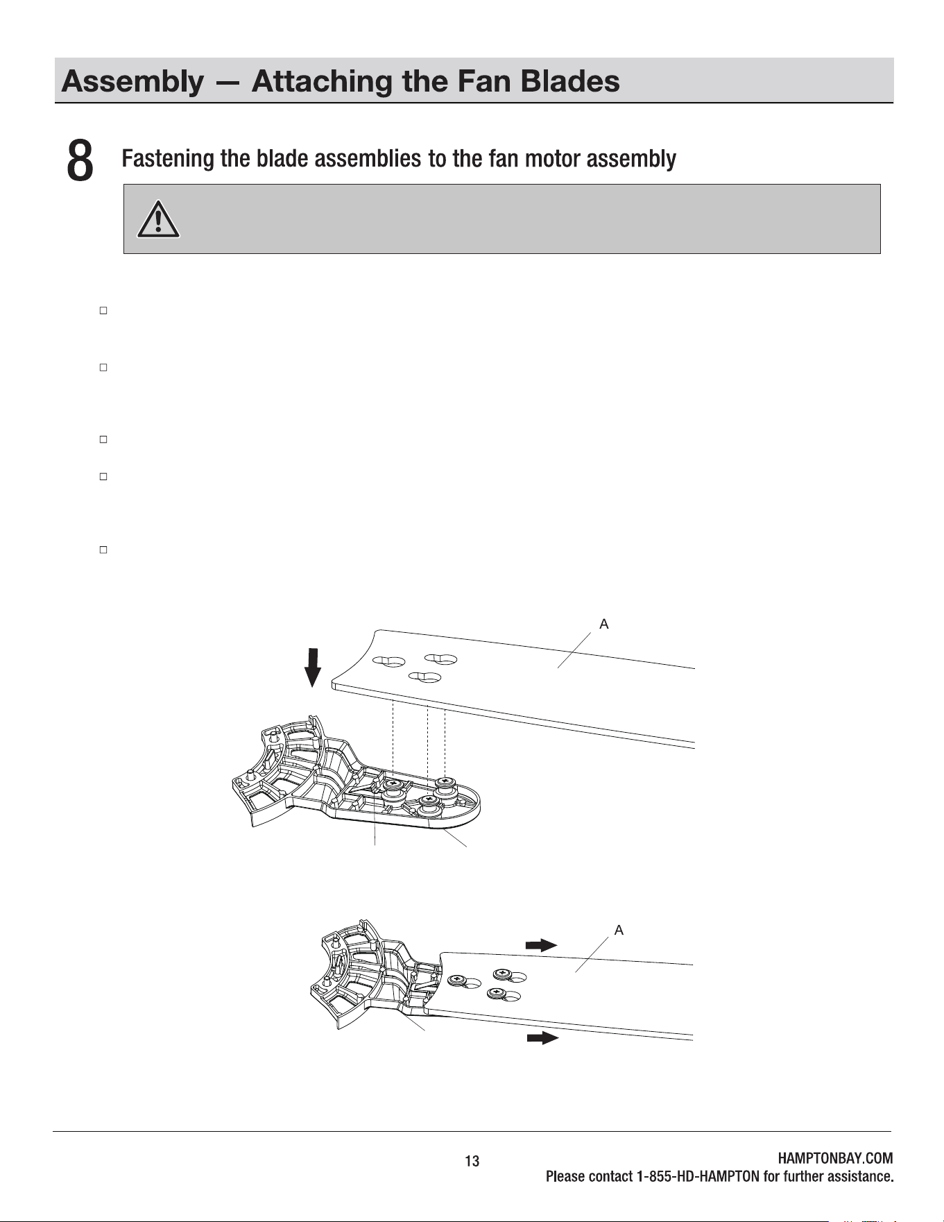
WARNING: Failure to properly seat the blades (A) on the blade arms (J) and engage in the locking mechanism (MM)
could result in the fan blades (A) loosening and possibly falling.
To install the blade to the blade arm:
Mount the fan blade (A) to the blade arm (J) by aligning the three key-slot holes in the blade (A) with the three posts on the top
of the blade arm (J).
Firmly slide the blade (A) away from the blade arm (J) until the blade (A) engages in the locking mechanism (MM). Make sure the
locking mechanism (MM) at the rear of the blade arm (J) springs upward and butts against the edge of the blade (A), indicating a
secure connection.
Visually inspect the top of the blade arm (J) to ensure the locking mechanism (MM) is securely in place.
Repeat this procedure for the remaining blades (A).
To detach the blade from the blade arm:
Press down the locking mechanism (MM) to release the blade (A) from the blade arm (J). Slide the blade (A) toward the blade
arm (J) until the blade (A) disengages from the locking mechanism (MM). Carefully push the blade (A) up to detach from the
bladearm (J).
H
J
A
BB
J
(BB)
J
J
A
J
CAUTION: To reduce the risk of electric shock, disconnect the electrical supply circuit to the fan before installing
the light kit.
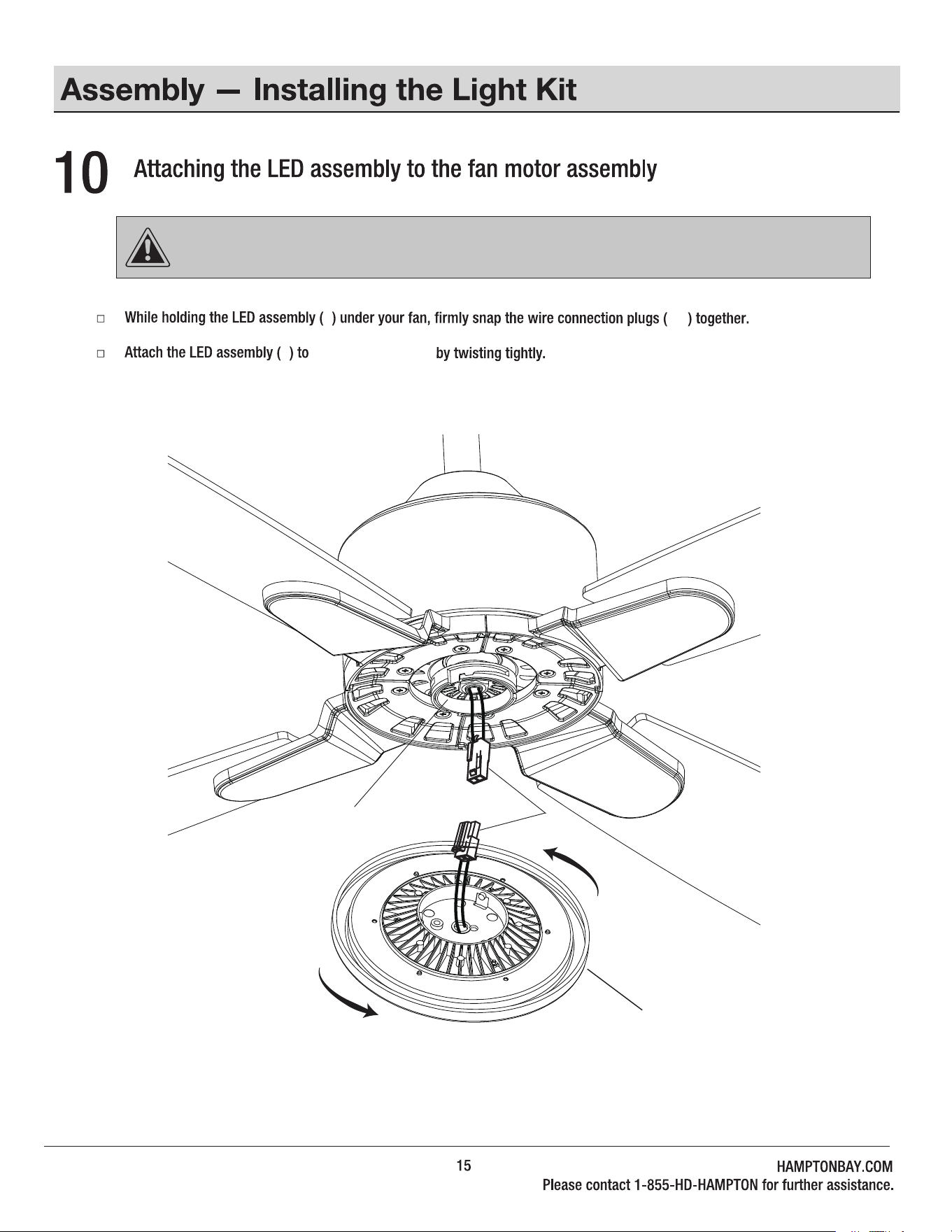
I
I
NN
I
NN
the switch box (OO)
OO
1.5V
1.5V
1.5V
Within 60 seconds of turning the fan's AC power ON, press and hold
the syncing button for 5 seconds to enter the learning function.
Once the receiver has detected the set frequency, the fan will rotate
for a while and the down light of your fan if applicable will blink twice.
The receiver has now learned the frequency which has been selected on
the transmitter. After completing the steps above, you should be able
to operate the ceiling fan and light. If the fan is not responding to the
transmitter, please turn the power off to the receiver, and repeat the
process.
NOTE: After the AC power is on, do not press any other
button on the remote control before pressing the syncing
button . Doing so will cause the procedure to fail.
Turn the power to the fan and light off. After 10 seconds, turn the
power back on to both the fan and light.
SYNCING THE RECEIVER AND THE REMOTE CONTROL
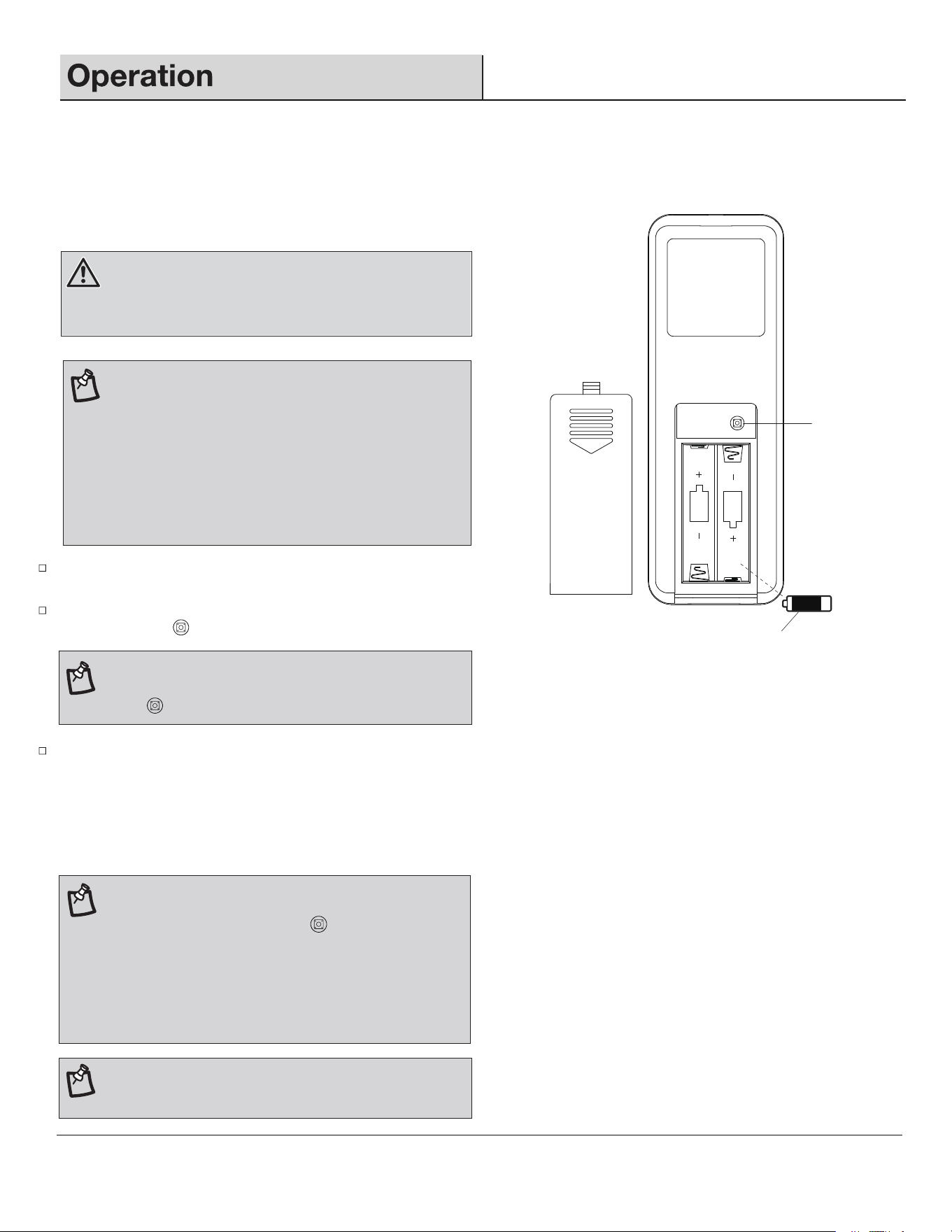
WARNING: Do not short-circuit, disassemble, heat up,
connect improperly, or dispose of used batteries in fire. Do
not recharge or mix batteries with used or other battery
types. Immediately remove used batteries.
NOTE: The control system isequipped with a learning
frequency function which has 64 code combinations to
prevent potential interference from other remote units. The
frequency on your receiver and transmitter units have been
preset at the factory. No frequency change is necessary. If
the fan is non-functional or if you desire to install another
fan within the same home or area with a separate
frequency code, please see this "learning process" section
of this instruction manual to re-pair the receiver and
transmitter.
N
Syncing
button
Install two 1.5V batteries (N) into the remote control. To prevent damage
to the remote control, remove the batteries if not used for long periods
of time. Restore power to the ceiling fan and test for proper operation.
16
NOTE: If you want to add an extra remote control to operate
the same fan, please follow the same steps as above but
instead of holding the sync button for 5 seconds, hold it
for 10 seconds on the additional remote controls you would
like to pair. During this 10 seconds, the light will blink twice
and the fan will run for a moment. The behavior will happen
twice. This is an indication that the new remote is paired,
and both remotes will work with the same fan.
NOTE: A maximum of 3 remote controls can be paired with
one fan.
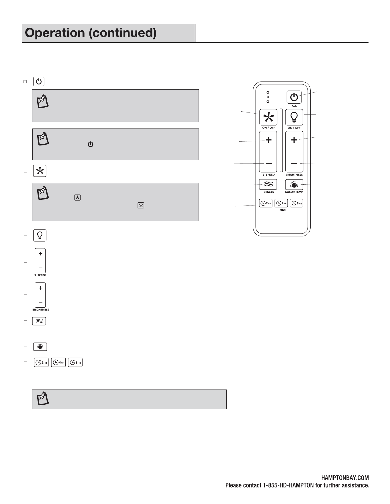
: Press and release this button to turn the fan and light on/off.
Fan & Light ALL ON/OFF
Increase the light
brightness
Decrease the light
brightness
Breeze mode
Timer
Change the light color to
3000K/4000K/5000K
Fan ON/OFF
Light ON/OFF
Increase the
fan speed
Decrease the
fan speed
NOTE: If you are currently using breeze mode,
pressing the button will cancel breeze mode and
resume normal fan operation.
: Press and release this button to dim the light.
: Press and release this button to turn the light on/off.
: Press and release the button to increase / decrease the fan speed. If fan is in Breeze mode, press and release this button to
cancel the Breeze mode and resume normal fan operation.
: Press and release this button to turn the fan on/off.
: Press and release the timer button to activate the timer function. The fan will automatically turn the
fan and light (if light is on) off after 2, 4 or 8 hours. Press and hold this button for 3 seconds to cancel the timer.
LEDs will blink 4 times, indicating cancellation of timer.
: Press and release this button to change the light color temperature to 3000K/4000K/5000K.
: Press and release this button to activate the Breeze mode. Press and hold this button for 3 seconds to cancel the
Breeze mode. LEDs will blink 4 times, indicating cancellation of Breeze mode.
NOTE: If Breeze mode is on, pressing the FAN ON/OFF
button will cancel Breeze mode and turn fan off.
Pressing the FAN ON/OFF button again will turn fan
on at the speed last engaged by Breeze mode.
REMOTE CONTROL OPERATING INSTRUCTIONS
NOTE: You must turn the fan on prior to using the timer function.
17
NOTE: The fan has memory function. It will resume
the speed and light setting on the ceiling fan prior
to the power being turned off.
H
SUMMER
MODE
WINTER
MODE
PP
PP
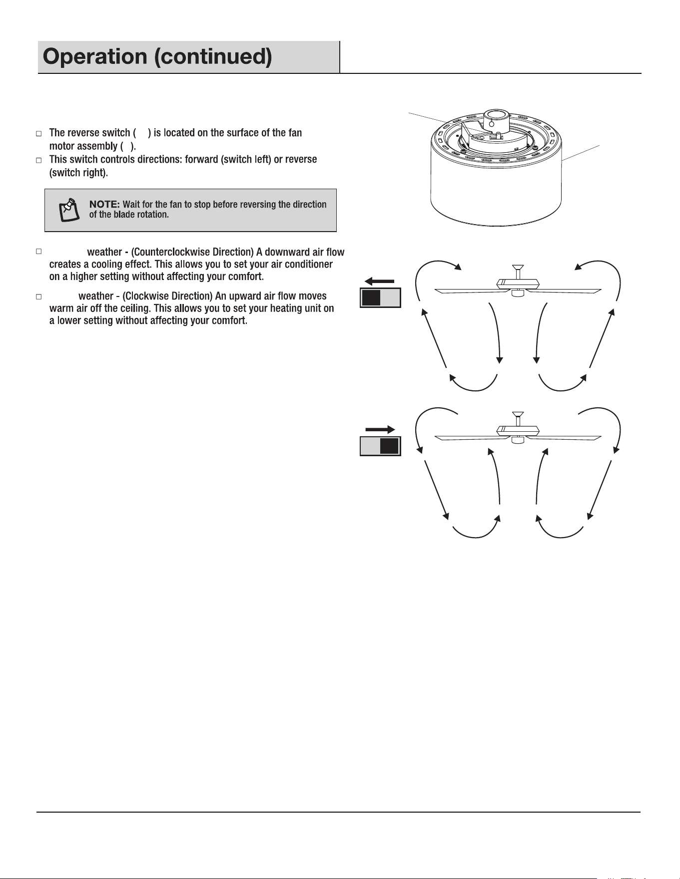
Winter
Summer
H
REVERSE FUNCTION
18
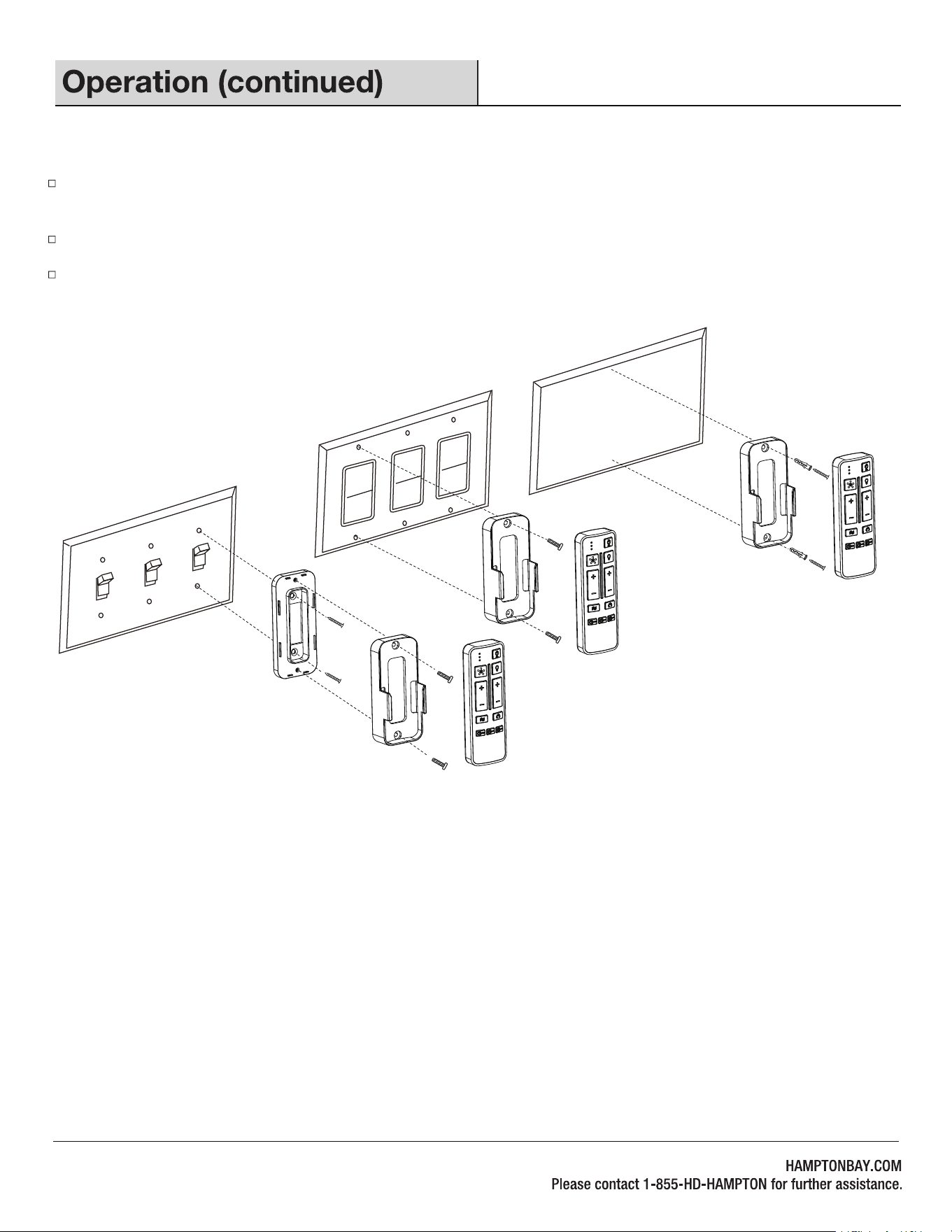
Option A : Remove wall plate screws, install the remote cradle to the spacer with hardware provided. Then screw the assembly into the
toggle switch wall plate with hardware provided.
Option B: Remove wall plate screws, install the remote cradle to the decorative switch wall plate with hardware provided.
Option C: Screw the remote cradle into drywall with hardware provided, with or without anchors.
19
INSTALLING THE REMOTE CONTROL CRADLE
ST3.5x13mm
ST3.0x18mm
A
B
C
#6/32*13mm
#6/32*13mm
Anchor

20
21
18W
1.5V
Remote control
Remote control cradle
Blade arm
22
1.5V
Remote control cradle hardware pack (ST3.5*13mm
screw -2pcs, ST3.0*18mm screw-2pcs, #6/32*13mm
screw-2pcs, anchor -2pcs)
Coupling
CF456KR-01
HAMPTON BAY