
Item #1012 002 050,
xxxx xxx xxx
Model #52411, 52410
UL Model #OSCW-18MD
THANK YOU
We appreciate the trust and condence you have placed in Hampton Bay through the purchase of this wall mount fan. We strive to
continually create quality products designed to enhance your home. Visit us online to see our full line of products available for your home
improvement needs. Thank you for choosing Hampton Bay!
Questions?
Before returning to the store, call Hampton Bay Customer Service
8 a.m. - 7 p.m., EST, Monday-Friday, 9 a.m. - 6 p.m., EST, Saturday
1-855-HD-HAMPTON
HAMPTONBAY.COM
USE AND CARE GUIDE
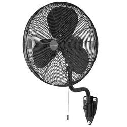
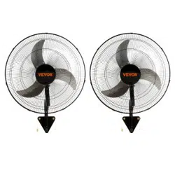
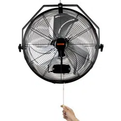
18 INCH HENTON WALL MOUNT FAN

2
Table of Contents..........................................................................2
Safety Information........................................................................2
Pre-Installation.............................................................................3
Assembly......................................................................................4
CAUTION: To reduce the risk of injury to persons, install
fan at least 2.1 m (7 feet) above the oor. Suitable for
commercial use only.
CAUTION: To reduce the risk of electric shock, connect
only to an outlet provided with a Ground Fault Circuit
Interrupting device.
WARNING: To reduce the risk of re or electrical shock,
DO NOT use this fan with any solid state speed control
device. This appliance has a 3-prong grounded plug that
must be inserted into a matching outlet. To reduce the risk
of electrical shock, this grounding plug must not be cut off.
Where a two-prong wall outlet is encountered, it must be
replaced: contact a qualied electrician. DO NOT attempt to
defeat this safety feature. Use your fan only with adequate
wiring that is up to code. Connect to properly grounded
outlets only.
WARNING: Unplug from electrical supply source before
cleaning. After servicing, any safety device (including grills
and blades) must be reinstalled or remounted as previously
installed.
NOTE: This fan is suitable for wet location. Suitable for
use in wet locations when installed in a GFCI Protected
Branch Circuit.
□ Always unplug unit for cleaning.
□ Always unplug unit when not in use.
□ Do not place foreign objects through guard into the blade.
□ Do not operate without fan guards properly locked.
□ Do not use this fan with an extension cord.
□ Do not place fan or any parts near an open ame, cooking or other
heating appliance.
□ Do not operate this unit with a damaged cord or plug, especially
when this unit has been malfunctioned, dropped or damaged.
Table of Contents
Operating Instructions.................................................................6
Cleaning........................................................................................6
Warranty........................................................................................6
READ AND SAVE THESE INSTRUCTIONS.
Safety Information
CAUTION: Read and follow all instructions before
operating fan. Do not use if any part is damaged or missing.
WARNING: To reduce the risk of re, electric shock
or injury to persons, do not use replacement parts that
have not been recommended by the manufacturer (e.g.
Parts made at home using a 3D Printer). Use only on GFCI
Protected receptacles.
WARNING: To reduce the risk of re, electric shock,
or other personal injury, mount fan only on an outlet box
or supporting system marked acceptable for fan support
of 50 lbs (22.67 kg) or less and use mounting screws
provided with the outlet box. Most outlet boxes commonly
used for the support of lighting xtures are not acceptable
for fan support and may need to be replaced. Consult a
qualied electrician if in doubt.

3
HAMPTONBAY.COM
Please contact 1-855-HD-HAMPTON for further assistance.
Part Description Quantity
A Motor assembly 1
B Rear grill 1
C Blade 1
D Front grill 1
E
Hexagonal nut /
Spring washer
5
PACKAGE CONTENTS
TOOLS REQUIRED
Phillips
screwdriver
Flat head
screwdriver
Step
ladder
Wrench
Part Description Quantity
F Wall mounting bracket 1
G Blade locking nut 1
H Screw 4
I Screw 10
J Screw 1
A
B
D
C
E
F
G
H
I
J
Pre-Installation

4
Installing the wall mounting bracket
to wall
1
□ Hang the bracket (F) on screws (I) through two big holes.
□ Determine the approximate position of where you want the
fan to be located on the wall. Locate the stud in the wall.
Position the wall mounting bracket (F) on wood stud or wood
post and mark the location of the four holes using a pencil or
a marker (not included).
□ Please note that the screw position is based on the small end
of the shaped hole.
□ Press down the bracket (F) so that the small ends of the two
special-shaped holes are matched with the two screws (I).
□ Tighten the four screws (I).
CAUTION: If you are going to attach the fan assembly (A)
to a wood stud or wood post or concrete wall, the stud or
wood post or concrete wall must be wide enough and thick
enough to sustain the wall mounting bracket (F) and the
weight of the fan assembly (A).
WARNING: To reduce the risk of the fan falling, use
all four mounting holes in the wall mounting bracket (F)
when installing.
WARNING: It is very important that you use the proper
hardware when installing the wall mounting bracket (F)
as this will support the fan assembly (A).
Assembly Instructions
F
I
7 ft.
F
I
F
1
2
3

5
HAMPTONBAY.COM
Please contact 1-855-HD-HAMPTON for further assistance.
□ Attach the four long holes at the bottom of
fan motor assembly (A) to the four hooks of
the wall bracket (F).
□ Install the screw (J) into the base screw
hole of the motor assembly (A) through
the bottom hole of the wall bracket (F) and
tighten it.
Assembling the rear grill
and blade
Assembling the front grill
3
4
□ Put the front grill (D) on the rear grill (B). The
mounting holes must correspond to each
other.
□ Screw the 10 screws (H) through the round
hole of rear grill (B) into the holes of front
grill (D) and tighten.
6
A
B
E
E
CAUTION: The groove behind the fan
blade (C) must t on the transverse pin
on the motor shaft.
TIP: Hand tighten will be better when
screwing on the grill. Power driver may
strip screws.
Assembly Instructions (continued)
Attaching motor assembly
2
4
A
F
5
J
A
7
A
C
G
□ Carefully slide the rear grill (B) over the
bolts.
□ Secure with the four spring washers and 4
hexagonal nut (E) and tighten.
□ Carefully slide the blade assembly (C) over
the shaft.
□ Screw in the blade lock nut (G) counter-
clockwise and tighten.
8
D
H
B

6
Speed control
Oscillating control
□ Plug in and pull the right pull chain to check the
power, low, middle, and high speed.
□ Pull the left pull chain to check the oscillating switch.
□ Use soft damp cloth then wipe with dry cloth. Do not use harmful cleaners. Do not bend the blades.
We warrant the fan motor to be free from defects in workmanship and material present at time of shipment from the factory for a period of
lifetime after the date of purchase by the original purchaser. We also warrant that all other fan parts, excluding any glass or acrylic blades, to
be free from defects in workmanship and material at the time of shipment from the factory for a period of one year after the date of purchase
by the original purchaser. We agree to correct such defects without charge or at our option replace with a comparable or superior model
if the product is returned. To obtain warranty service, you must present a copy of the receipt as proof of purchase. All costs of removing
and reinstalling the product are your responsibility. Damage to any part such as by accident, misuse, improper installation or by afxing
any accessories, is not covered by this warranty. Because of varying climatic conditions this warranty does not cover any changes in brass
nish, including rusting, pitting, corroding, tarnishing or peeling. Brass nishes of this type give their longest useful life when protected
from varying weather conditions. A certain amount of “wobble” is normal and should not be considered a defect. Servicing performed by
unauthorized persons shall render the warranty invalid. There is no other express warranty. We hereby disclaim any and all warranties,
including but not limited to those of merchantability and tness for a particular purpose to the extent permitted by law. The duration of any
implied warranty which cannot be disclaimed is limited to the time period as specied in the express warranty. Some states do not allow
limitation on how long an implied warranty lasts, so the above limitation may not apply to you. The retailer shall not be liable for incidental,
consequential, or special damages arising out of or in connection with product use or performance except as may otherwise be accorded by
law. Some states do not allow the exclusion of incidental or consequential damages, so the above exclusion or limitation may not apply to
you. This warranty gives specic legal rights, and you may also have other rights which vary from state to state. This warranty supersedes
all prior warranties. Shipping costs for any return of product as part of a claim on the warranty must be paid by the customer.
Contact the Customer Service Team at 1-855-HD-HAMPTON or visit www.HamptonBay.com.
Warranty
9
ON-OFF
OFF-H-M-L
Operating Instructions
Cleaning

Net weight: 15.87 lbs (7.2 kgs)
Gross weight: 28.22 lbs (12.8 kgs)
Cubic Feet: 4.38 ft
3
Questions, problems, missing parts? Before returning to the store,
call Hampton Bay Customer Service
8 a.m. – 7 p.m., EST, Monday – Friday, 9 a.m. – 6 p.m., EST, Saturday
1-855-HD-HAMPTON
HAMPTONBAY.COM
Retain this manual for future use.

Artículo #1012 002 050,
xxxx xxx xxx
Modelo #52411, 52410
Modelo UL #OSCW-18MD
VENTILADOR DE PARED HENTON DE 45.72 CM
GRACIAS
Apreciamos la plena conanza que has depositado en Hampton Bay al comprar este ventilador de techo. Nos esforzamos en crear
continuamente productos de calidad diseñados para mejorar tu hogar. Visítanos por Internet para ver nuestra línea completa de productos
disponibles a n de satisfacer la necesidades de mejoras de tu hogar. ¡Gracias por elegir Hampton Bay!
¿Preguntas?
Antes de devolver a la tienda, llama al Servicio al Cliente de Hampton Bay de lunes a viernes
de 8 a.m. a 7 p.m. (Hora del Este) o los sábados de 9 a.m. a 6 p.m. (Hora del Este).
1-855-HD-HAMPTON
HAMPTONBAY.COM
GUÍA DE USO Y MANTENIMIENTO

2
Tabla de contenido.......................................................................2
Información de seguridad............................................................2
Preinstalación..............................................................................3
Ensamblaje...................................................................................4
CUIDADO: Lee y sigue todas las instrucciones antes de poner
en operación el ventilador. No uses el ventilador si alguna de las
piezas falta o está dañada.
CUIDADO: Para disminuir el riesgo de lesiones físicas, instala
el ventilador a una altura mínima de 2.1 m (7 pies) del piso. Apto
para uso comercial solamente.
CUIDADO: Para reducir el riesgo de descarga eléctrica,
conéctalo únicamente a un tomacorrientes que cuente con un
dispositivo de interrupción del circuito de fallos por conexión
a tierra.
ADVERTENCIA: Para reducir el riesgo de incendio o descarga
eléctrica, NO uses este ventilador con ningún dispositivo de
control de velocidad de estado sólido. Este electrodoméstico
tiene un enchufe de 3 clavijas con conexión a tierra, que tiene
que insertarse en un tomacorrientes adecuado. Para reducir el
riesgo de descargas eléctricas, no debe cortarse la clavija del
enchufe que conecta a tierra. Si se encuentra un tomacorriente
de pared con dos clavijas, tiene que ser reemplazado: contactar
a un electricista calicado. NO intentes anular este sistema de
seguridad. Utiliza el ventilador sólo con cableado adecuado que
cumpla con las regulaciones. Sólo conéctalo a tomacorrientes
que estén apropiadamente conectados a tierra.
ADVERTENCIA: Antes de limpiarlo, desenchúfalo de la fuente
de electricidad. Luego del mantenimiento, todos los dispositivos
de seguridad (incluyendo las rejillas y aspas) tienen que
reinstalarse tal y como estaban antes.
ADVERTENCIA: Para reducir los riesgos de incendio,
descarga eléctrica o lesiones personales, no uses repuestos
que no sean recomendados por el fabricante (p. ej., piezas
hechas en casa con una impresora 3D). Úsalo únicamente en
receptáculos protegidos con GFCI.
ADVERTENCIA: Para reducir el riesgo de incendio, descarga
eléctrica o lesiones personales, instala el ventilador sólo en una
caja eléctrica o sistema de soporte aprobados para ventiladores
de 22.67 kg (50 lb) o menos, y usa los tornillos de montaje que
vienen con la caja eléctrica. La mayoría de las cajas eléctricas
comúnmente usadas para soporte de lámparas no son aceptables
como soporte de ventilador y sería necesario reemplazarlas.
Consulta a un electricista calicado en caso de duda.
NOTA: Este ventilador es apto para lugares húmedos. Adecuado
para usar en lugares húmedos si se instala en un circuito GFCI
protegido por interruptor diferencial (GFCI).
□ Desconecta siempre la unidad antes de limpiarla.
□ Desconecta el ventilador siempre que no esté en uso.
□ No introduzcas objetos extraños en las aspas a través del protector.
□ No pongas el ventilador en funcionamiento si su protector no está
debidamente asegurado.
□ No uses este ventilador con una extensión eléctrica
□ No coloques el ventilador ni ninguna de sus piezas cerca del fuego o
de otros electrodomésticos para cocción o calefacción.
□ No utilices el ventilador con un cable o enchufe dañado,
especialmente si la unidad está fallando, se cayó o sufrió daños.
Tabla de contenido
Instrucciones de operación.........................................................6
Limpieza........................................................................................6
Garantía........................................................................................6
LEE Y GUARDA ESTAS INSTRUCCIONES.
Información de seguridad

3
HAMPTONBAY.COM
Para asistencia adicional, llama al 1-855-HD-HAMPTON.
Pieza Descripción Cantidad
A Ensamblaje del motor 1
B Rejilla posterior 1
C Aspa 1
D Rejilla frontal 1
E
Tuerca hexagonal /
Arandela de resorte
5
CONTENIDO DEL PAQUETE
HERRAMIENTAS NECESARIAS
Phillips
screwdriver
Flat head
screwdriver
Step
ladder
Wrench
Pieza Descripción Cantidad
F Soporte de montaje en la pared 1
G Tuerca de bloqueo de aspa 1
H Tornillo 4
I Tornillo 10
J Tornillo 1
A
B
D
C
E
F
G
H
I
J
Preinstalación
Destornillador
Phillips
Destornillador de
cabeza plana
Escalera
de tijera
Llave

4
Cómo instalar el soporte para
montaje en la pared
1
□ Cuelga el soporte (F) en los tornillos (I) a través de dos
oricios grandes.
□ Determina la posición aproximada en la que deseas que el
ventilador quede en la pared. Ubica la viga en la pared. Coloca
el soporte para montaje en la pared (F) en la viga o poste,
y marca la ubicación de los cuatro oricios con un lápiz o
marcador (no incluido).
□ Ten en cuenta que la posición del tornillo se basa en el
extremo pequeño del oricio moldeado.
□ Presiona hacia abajo el soporte (F) de modo que los extremos
pequeños de los dos oricios de forma especial coincidan con
los dos tornillos (I).
□ Aprieta los cuatro tornillos (I).
CUIDADO: Si vas a instalar el ensamblaje del ventilador (A) a
una viga o poste de madera o pared de concreto, debe tener el
ancho y grosor suciente para sostener el soporte para montaje
en la pared (F) y el peso del conjunto del ventilador (A).
ADVERTENCIA: Para reducir el riesgo de que el ventilador
se caiga, usa los cuatro oricios de montaje del soporte para
montaje en la pared (F) al instalar el soporte.
ADVERTENCIA: Es muy importante que utilices los herrajes
adecuados al instalar el soporte para montaje en la pared (F)
pues este sostendrá el conjunto del ventilador (A).
Instrucciones de ensamblaje
F
I
7 ft.
F
I
F
1
2
3
2.1 m (7 pies)

5
HAMPTONBAY.COM
Para asistencia adicional, llama al 1-855-HD-HAMPTON.
□ Conecta los cuatro oricios largos en la
parte inferior del conjunto del motor del
ventilador (A) a los cuatro ganchos del
soporte de pared (F).
□ Instala el tornillo (J) en el oricio del tornillo
de la base del conjunto del motor (A) a
través del oricio inferior del soporte de
pared (F) y apriétalo.
Cómo ensamblar la rejilla
posterior y el aspa
Cómo ensamblar la rejilla frontal
3
4
□ Coloca la rejilla delantera (D) sobre la rejilla
posterior (B). Los oricios de montaje deben
corresponder entre sí.
□ Atornilla los 10 tornillos (H) a través del
oricio redondo de la rejilla posterior (B) en
los oricios de la rejilla frontal (D) y apriétalos.
6
A
B
E
E
CUIDADO: La ranura detrás del aspa del
ventilador (C) debe encajar en el pasador
transversal del eje del motor.
CONSEJO: Será mejor apretarlo con la
mano al atornillar la rejilla. El destornillador
eléctrico puede barrer los tornillos.
Instrucciones de ensamblaje (continuación)
Cómo jar el conjunto
del motor
2
4
A
F
5
J
A
7
A
C
G
□ Desliza con cuidado la rejilla posterior (B)
sobre los pernos.
□ Asegura con las cuatro arandelas de resorte y
las 4 tuercas hexagonales (E) y aprieta.
□ Desliza con cuidado el conjunto de aspas (C)
sobre el eje.
□ Atornilla la tuerca de seguridad del aspa (G)
en sentido contrario a las manecillas del reloj
y apriétala.
8
D
H
B

6
Control de velocidad
Control de oscilación
□ Conecta y tira de la cadena derecha para comprobar
la potencia y la velocidad baja, media y alta.
□ Tira de la cadena izquierda para comprobar el
interruptor oscilante.
□ Usa un paño suave húmedo y pasa enseguida uno seco. No uses limpiadores que puedan causar daños. No dobles las aspas.
Garantizamos de por vida, a partir de la fecha de adquisición por el comprador original, que el motor del ventilador no presenta defectos de
fabricación ni de materiales al momento del envío desde la fábrica. También garantizamos por un año, a partir de la fecha de adquisición por
el comprador original, que las demás piezas del ventilador, sin incluir aspas de vidrio o acrílico, no presentan ningún defecto de fabricación
ni de material al momento de la salida de la fábrica. Si el producto es devuelto, aceptamos reparar sus defectos sin cargo alguno o, a
nuestra discreción, reemplazarlo por un modelo similar o superior. Para obtener servicio de garantía tiene que presentar una copia del
recibo como comprobante de compra. Todos los costos de retiro y reinstalación del producto correrán por tu cuenta. Los daños a cualquier
pieza por accidente, instalación o uso inadecuado, o por montar cualquier accesorio, no están cubiertos por esta garantía. Puesto que las
condiciones climáticas pueden variar, esta garantía no cubre ningún cambio del acabado en latón, como óxido, perforación, corrosión,
manchas o descascaramiento. Los acabados en latón de este tipo proveen la vida útil más larga al proteger contra las condiciones climáticas
cambiantes. Cierta “oscilación” es normal y no debe considerase un defecto. Cualquier servicio prestado por personal no autorizado
invalidará la garantía. No hay ninguna otra garantía expresa. Por este medio rechazamos todas y cada una de las garantías, incluyendo, pero
sin limitarse a, aquellas de comercialización e idoneidad para determinado n, en el alcance permitido por la ley. La duración de cualquier
garantía implícita que no pueda rechazarse se limita al plazo especicado en la garantía explícita. Algunos estados no permiten limitar la
duración de la garantía; por consiguiente, la limitación anterior pudiera no aplicarse a su caso. El minorista no será responsable por daños
directos, indirectos ni especiales que resulten o deriven del uso o funcionamiento del producto, excepto en los casos que pudieran estar
estipulados de otro modo por ley. Algunos estados no permiten excluir ni limitar daños directos o indirectos, así que la limitación o exclusión
anterior pudiera no aplicarse a su caso. Esta garantía concede derechos legales especícos y es posible que usted tenga también otros
derechos, que varían de estado a estado. Esta garantía sustituye todas las precedentes. Los costos de envío en cualquier devolución de
productos como parte de un reclamo de garantía corren por cuenta del cliente.
Comuníquese con el Equipo de Servicio al Cliente al 1-855-HD-HAMPTON o visite www.HamptonBay.com.
Garantía
9
ON-OFF
OFF-H-M-L
Instrucciones de uso
Limpieza
ENCENDIDO-APAGADO
APAGADO-ALTO-MEDIO-BAJO

Peso brutot: 15.87 lbs (7.2 kgs)
Peso neto: 28.22 lbs (12.8 kgs)
Pies cúbicos: 4.38 pies
3
¿Preguntas, problemas o piezas faltantes? Antes de devolver a la tienda,
llama al Servicio al Cliente de Hampton Bay de lunes a viernes de 8 a.m. a 7 p.m. (Hora del Este)
o los sábados de 9 a.m. a 6 p.m. (Hora del Este).
1-855-HD-HAMPTON
HAMPTONBAY.COM
Conserva este manual para referencias futuras.