
1
Item #1001-419-054
Model #7114-01
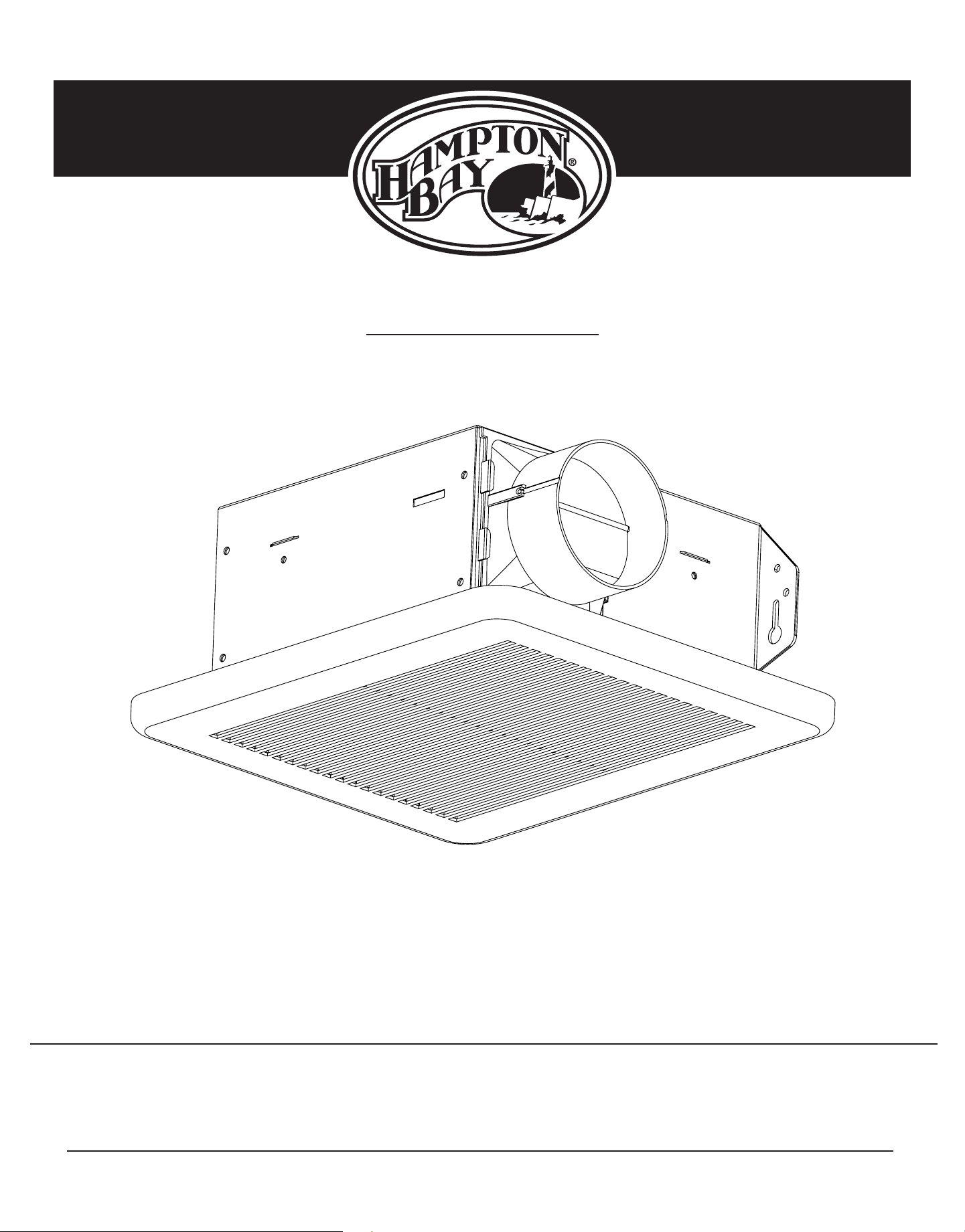
USE AND CARE GUIDE
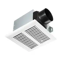
NO CUT EASY INSTALL VENTILATION FAN
Questions, problems, missing parts? Before returning to the store,
call Hampton Bay Customer Service
8 a.m. - 7 p.m., EST, Monday-Friday, 9 a.m. - 6 p.m., EST Saturday
1-855-HD-HAMPTON
HAMPTONBAY.COM
THANK YOU
We appreciate the trust and confidence you have placed in Hampton Bay through the purchase of this ventilating bath fan. We strive to
continually create quality products designed to enhance your home. Visit us online to see our full line of products available for your home improvement needs.
Thank you for choosing Hampton Bay!

2
Table of Contents ........................................................... 2
Safety Information .......................................................... 2
Product Specications ................................................... 3
Typical Installation .......................................................... 3
Wiring Diagram ............................................................... 3
Quick connector instructions ...................................................3
Warranty .......................................................................... 4
LIMITED LIFETIME WARRANTY ................................................4
What is Covered......................................................................4
Pre-installation................................................................ 4
Planning Installation ................................................................4
Tools Required ........................................................................4
Package Contents ...................................................................5
Installation - New Construction .................................... 6
Installation - Existing Construction .............................. 8
Care and Maintenance ................................................. 11
Troubleshooting ............................................................ 11
Table of Contents
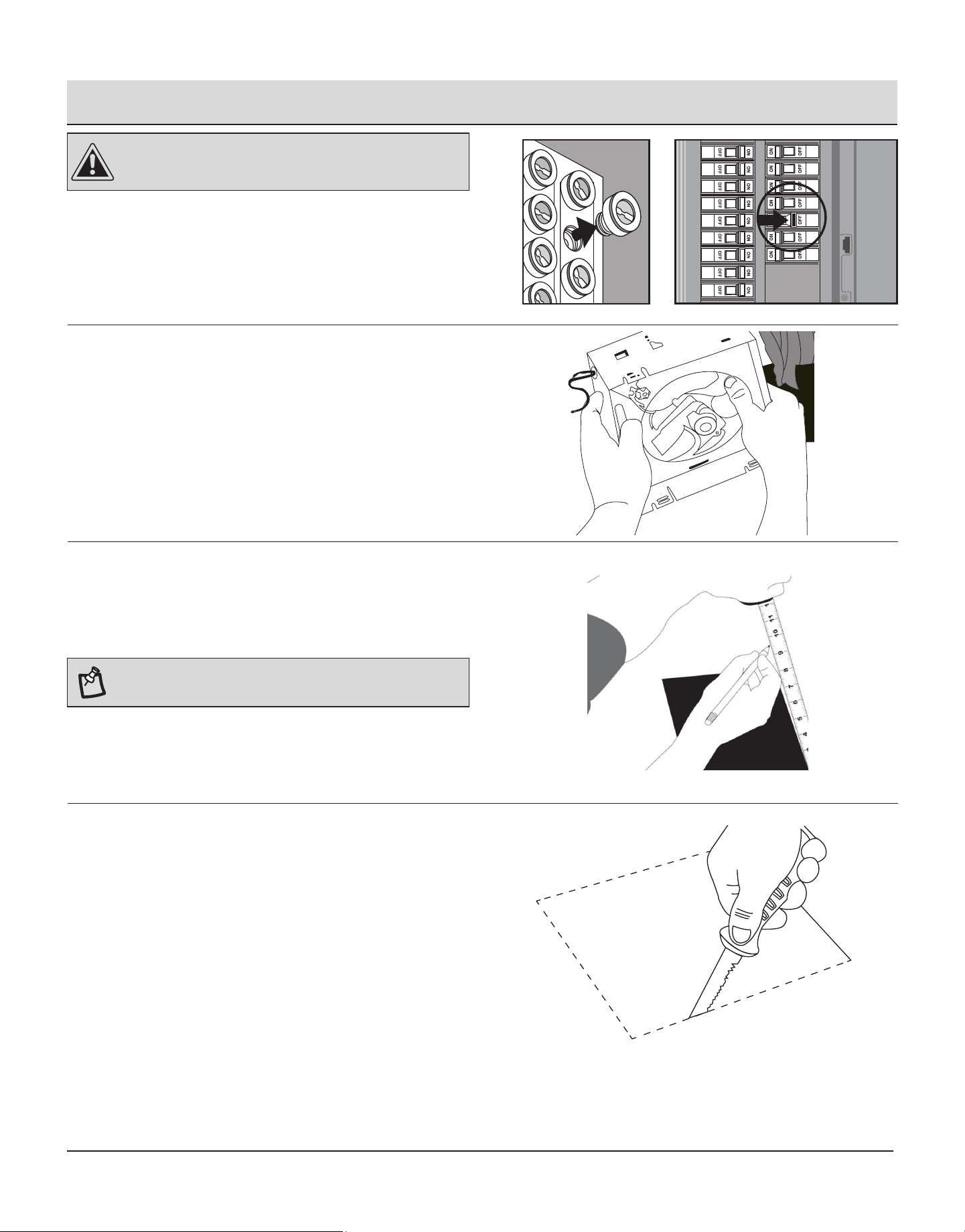
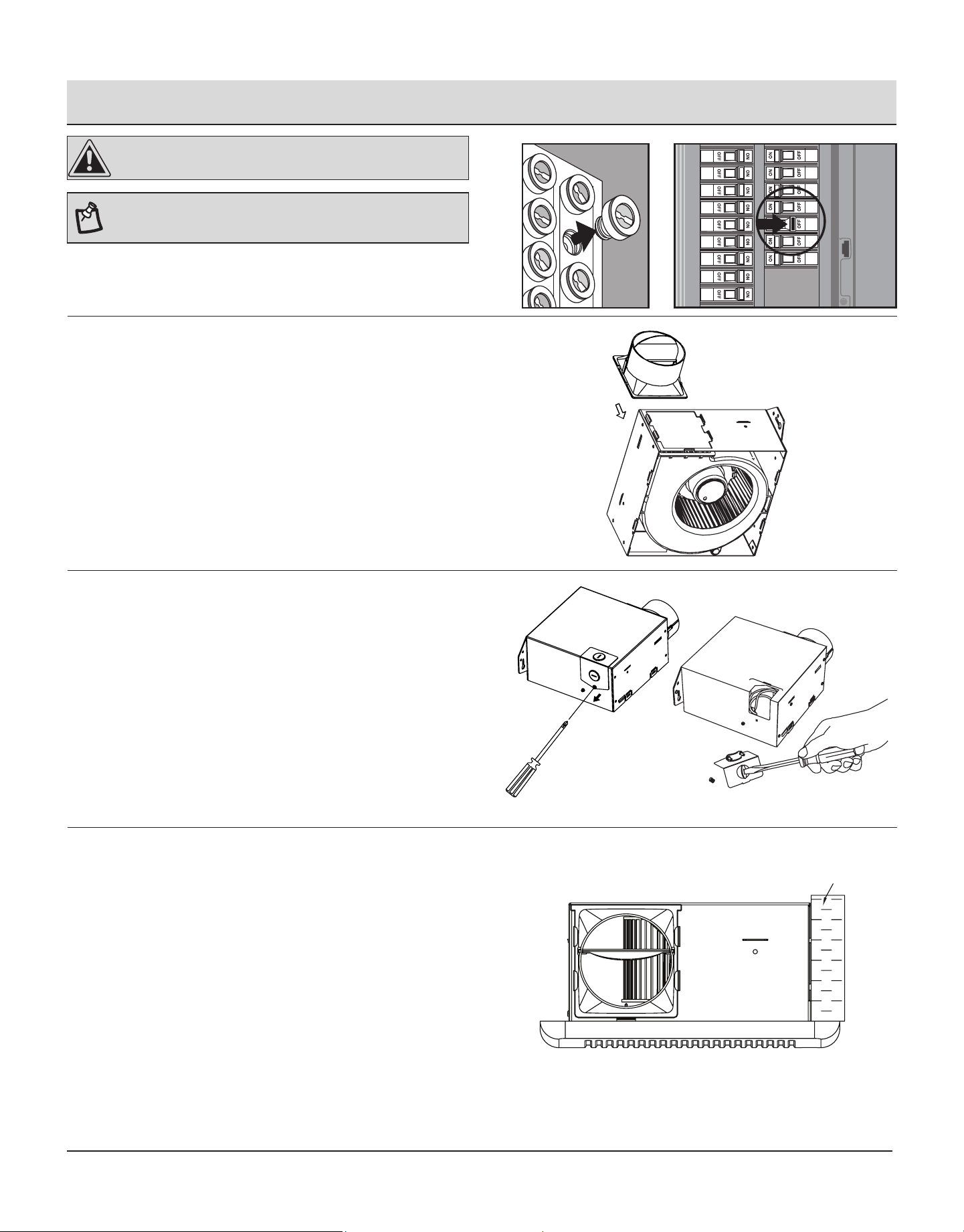
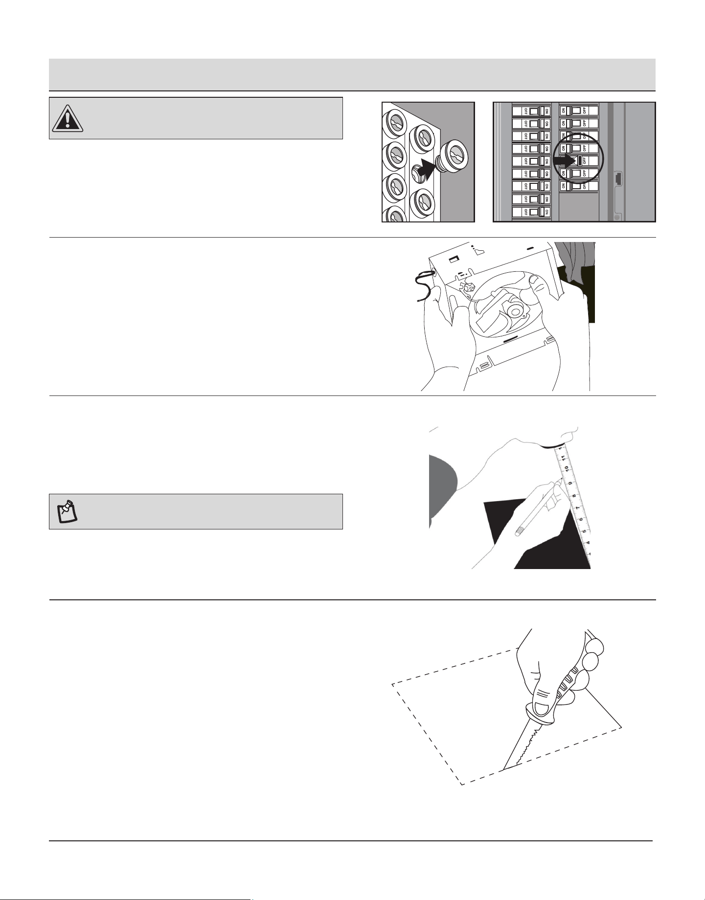
Safety Information
Please read and understand this entire manual before attempting to assemble, operate or install the
product.
1. Always disconnect the power supply prior to servicing the fan, motor or junction box.
2. Follow all local building, safety and electrical codes as well as NEC (National Electrical Code) and OSHA (Occupational Safety and Health Act).
3. Electric Service supply must be 120 volts, 60 hertz.
4. This product must properly connect to the grounding conductor of the supply circuit.
5. Do not bend or kink the power wires.
6. Do not use this fan with any solid state control device, such as a remote control, dimmer switch, or certain timers. Mechanical timers are not
solid state devices.
7. Do not install in a ceiling with insulation greater than R40.
8. Duct work should be installed in a straight line with minimal bends.
9. Duct work size must be the same size as the discharge and should not be reduced. Reducing the duct size may increase fan noise.
WARNING
TO REDUCE THE RISK OF FIRE, ELECTRIC SHOCK, OR INJURY TO PERSONS, OBSERVE THE FOLLOWING:
1. Use this unit in the manner intended by the manufacturer. If you have any questions. Please call customer service.
2. Before servicing or cleaning unit, switch power off at service panel and lock the service disconnecting means to prevent power from being
switched on accidentally. When the service disconnecting means cannot be locked, securely fasten a prominent warning device, such as a tag,
to the service panel.
3. Installation work and electrical wiring must be done by a qualied person(s) in accordance with all applicable codes and standards, including
re-rated construction.
4. Sufcient air is needed for proper combustion and exhausting of gases through the ue (chimney) of fuel burning equipment to prevent backdrafting.
Follow the heating equipment manufacturer’s guideline and safety standards such as those published by the National Fire Protection Association
(NFPA), and the American Society for Heating, Refrigeration and Air Conditioning Engineers (ASHRAE) and local code authorities.
5. When cutting or drilling into the wall or ceiling, do not damage electrical wiring and other hidden utilities.
6. Ducted fans must always be vented to the outdoors.
7. If this unit is to be installed over a tub or shower, it must be marked as appropriate for the application and be connected to a GFCI (Ground Fault
Circuit Interrupter) – protected branch circuit.
CAUTION
1. For general ventilating use only. Do not use to exhaust hazardous or explosive materials and vapors.
2. Not for use in cooking areas.
3. To reduce the risk of injury to persons, install the fan at least 8.2 feet (2.5m) above the oor.
3
HAMPTONBAY.COM
Please contact 1-855-HD-HAMPTON for further assistance.
Product Specication
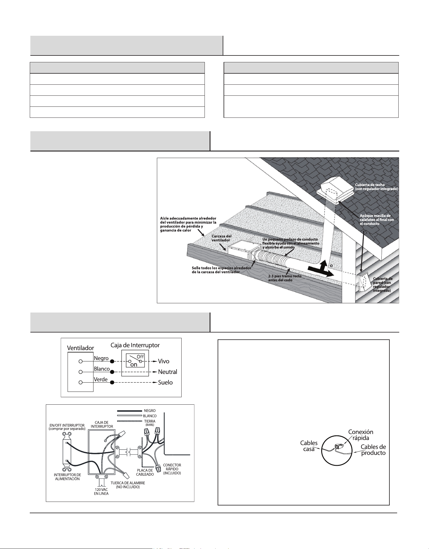
Typical Installation
Wiring Diagram
SPECIFICATIONS SPECIFICATIONS
Airow: 50 CFM Power consumption: 8.0 W
120 V, 60 Hz Weight: 3.65 lbs.
Duct diameter: 3 in.
Ceiling Opening Dimension Requirements: 7-1/2 in. (L) x 7-1/4 in. (W)
x 4 in. (H)
Sound output: 1.0 Sone
QUICK CONNECTOR INSTRUCTIONS
To be sold only with installation instructions.
WARNING: Wiring must comply with all applicable electrical
codes. Turn OFF power before removing or installing connectors.
WARNING: COPPER TO COPPER ONLY. Do not use Aluminum wire.
CAUTION: Accessory part (quick connector) should meet
installation instructions below.
NOTE: The connector is reusable on solid wires of the same wire gage or
smaller. Do not reuse the connector on stranded wires.
• Strip wires 3/8"-1/2"
• Grip the wire firmly and push
the stripped end of the wire into
the open port of the connector.
Use only one conductor
per port.
• Verify the stripped end of the
wires is fully inserted to the
back of the connector.
Quick
connect
House
wires
Product
wires
NOTE: Important wire information. Maximum temperature rating 105˚C
(221˚F). 600 volts maximum for building wire and 1000 volts maximum for
building wire and 1000 volts maximum in signs and lighting xtures.
The acceptable wire range includes: Solid: 12-18 AWG.
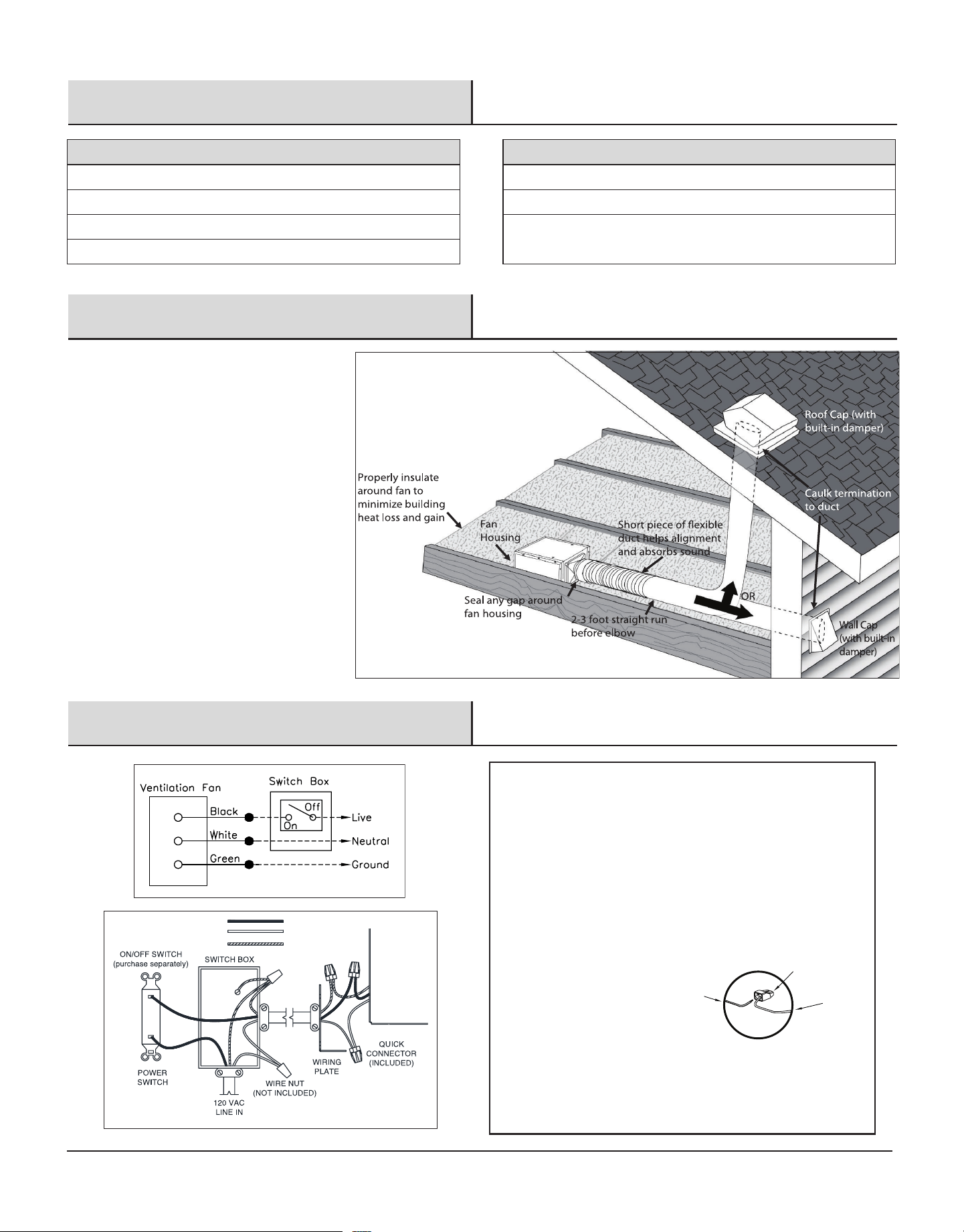
The ducting from this fan to the outside of the
building has a strong effect on the air ow, noise and
energy use of the fan. Use the shortest, straightest
duct routing possible for best performance, and
avoid installing the fan with smaller ducts than
recommended. Insulation around the ducts can
reduce energy loss and inhibit mold growth. Fans
installed with existing ducts may not achieve
their rated air ow.
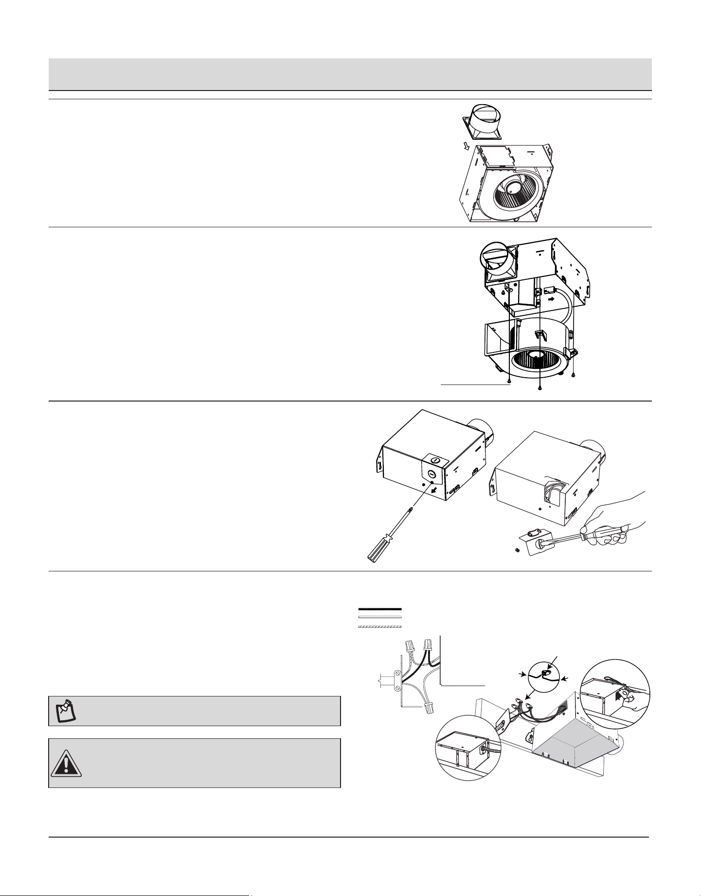
BLACK (LIVE)
WHITE (NEUTRAL)
GREEN (GROUND)
FAN
4
LIMITED LIFETIME WARRANTY
WHAT IS COVERED
If this product fails due to a defect in materials or workmanship at any time during the rst FIVE years of ownership, the manufacturer will replace it free
of charge, postage-paid at their option. This warranty does not cover products that have been abused, altered, damaged, misused, cut or worn. This
warranty does not cover use in commercial applications. Use only manufacturer-supplied genuine warranty repair replacement parts to repair this fan. Use of
non-genuine repair parts will void your warranty. The manufacturer DISCLAIMS all other implied or express warranties including all warranties of merchant-
ability and/or tness for a particular purpose. As some states do not allow exclusions or limitations on an implied warranty, the above exclusions and
limitations may not apply. This warranty gives you specic legal rights, and you may have other rights that vary from state to state.
This warranty is limited to the replacement of defective parts only. Labor charges and/or damage incurred during installation, repair, replacement as well
as incidental and consequential damages connected with the above are excluded. Any damage to this product as a result of neglect, misuse, accident,
improper installation or use other than the purpose SHALL VOID THIS WARRANTY. Shipping costs for return product as part of a claim on the warranty
must be paid for by the customer.
Contact the Customer Service Team at 1-855-HD-HAMPTON or visit www.HAMPTONBAY.com.
Warranty
Pre-installation
PLANNING INSTALLATION
Before beginning assembly of the product, make sure all parts are present. Compare parts with the package contents list and hardware contents. If
any part is missing or damaged, do not attempt to assemble the product.
WARNING: Turn off electricity at breaker box before beginning
installation.
Carefully remove the unit from the carton.
Check area above installation location to be sure that wiring can run to the planned location and that duct work can be run and the area is sufcient
for proper ventilation.
Inspect duct work and wiring before proceeding with installation.
Before installation, provide inspection and future maintenance access at a location that will not interfere with installation work.
You may need the help of a second person to install this fan; one person on the attic side and one on the room side.
NOTE: Installation may vary depending on how the previous bath fan
was installed. Supplies necessary for the installation of your bath fan are
not all included. However, most are available at your local home
improvement or hardware store.
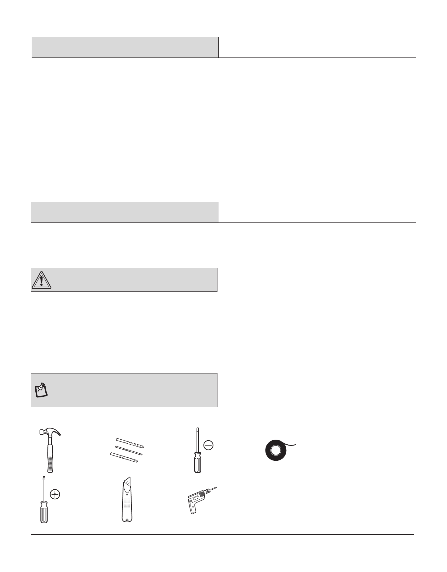
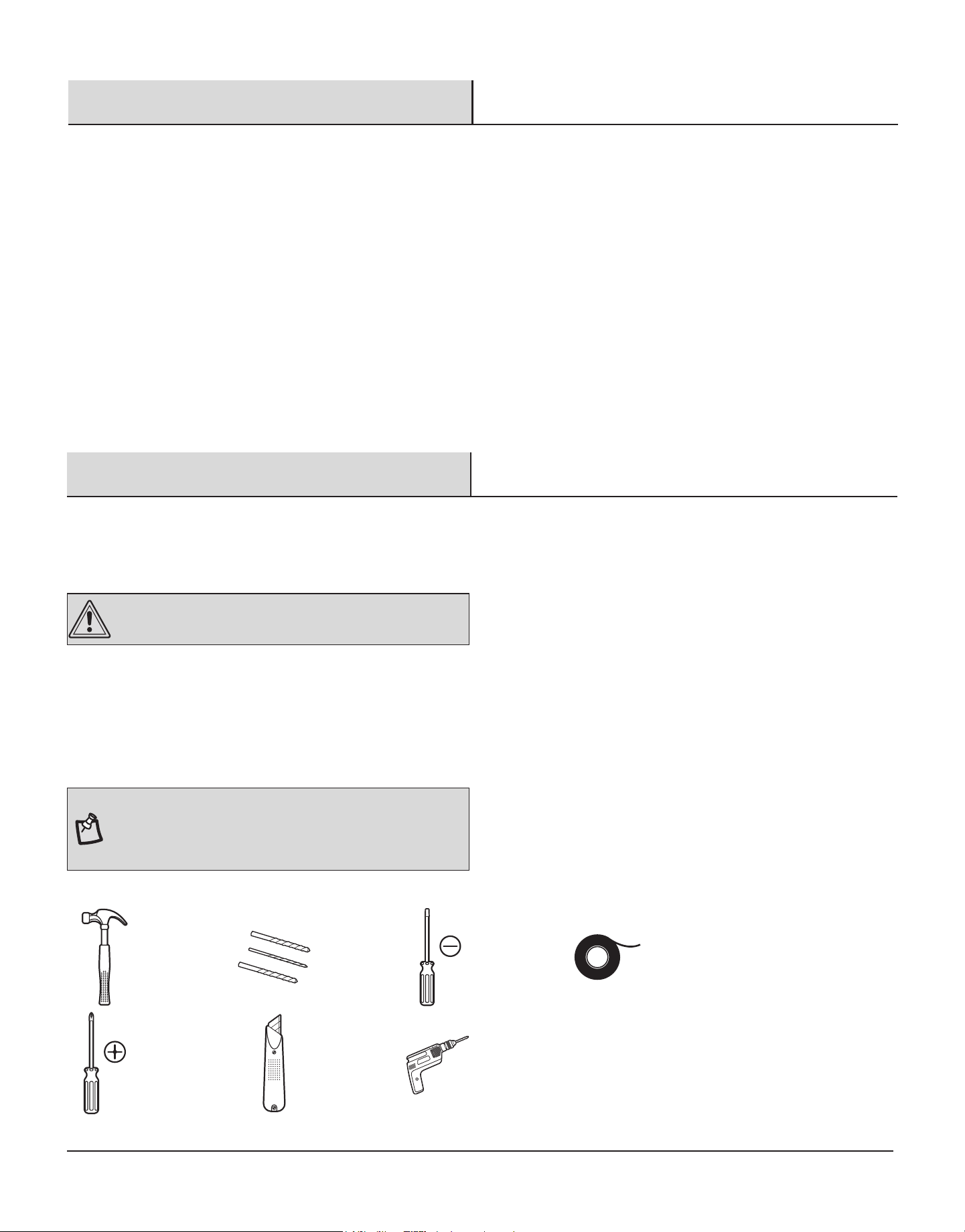
TOOLS REQUIRED (not included)
Claw
hammer
Drill
bits
Flathead
screwdriver
Duct
tape
Phillips head
screwdriver
Utility
knife
Electric
drill
5
HAMPTONBAY.COM
Please contact 1-855-HD-HAMPTON for further assistance.
Pre-installation (continued)
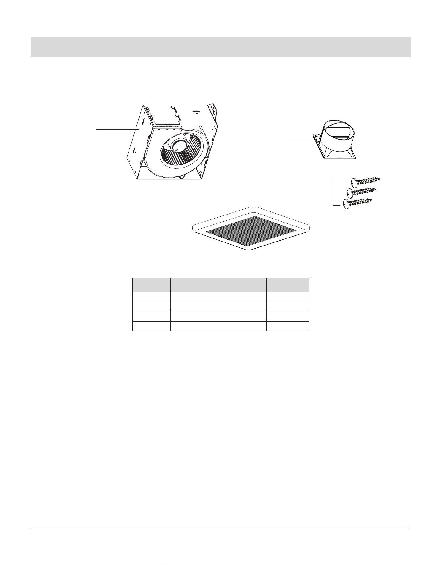
PACKAGE CONTENTS
Part Description Quantity
A Fan housing 1
B Grille 1
C Duct connector 1
D Long wood screws (ø4x25mm) 3
A
B
C
D
6
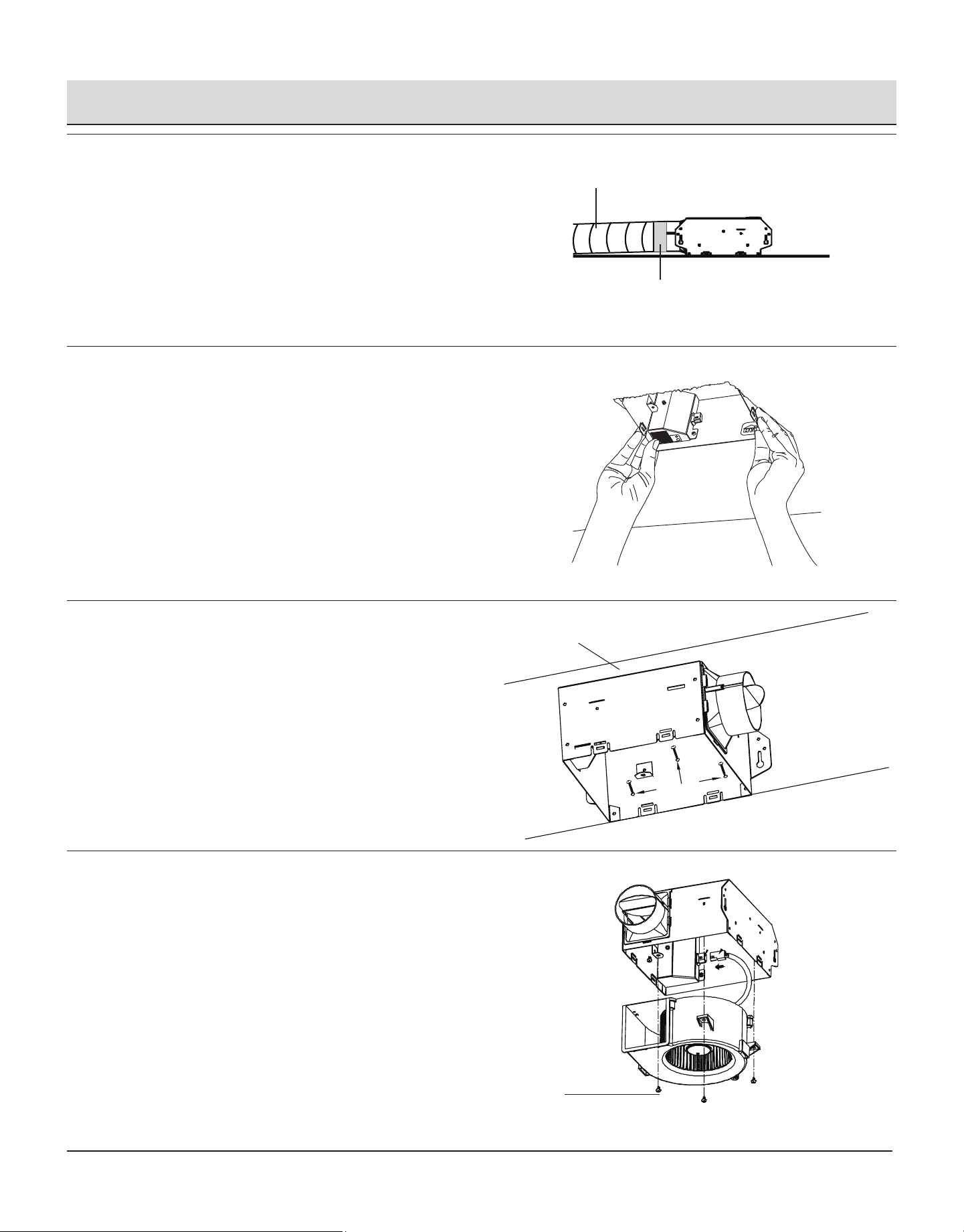
Installation - New Construction
CAUTION: Make sure power is switched o at service
panel before starting installation.
NOTE: Unit can be mounted in a ceiling or wall.
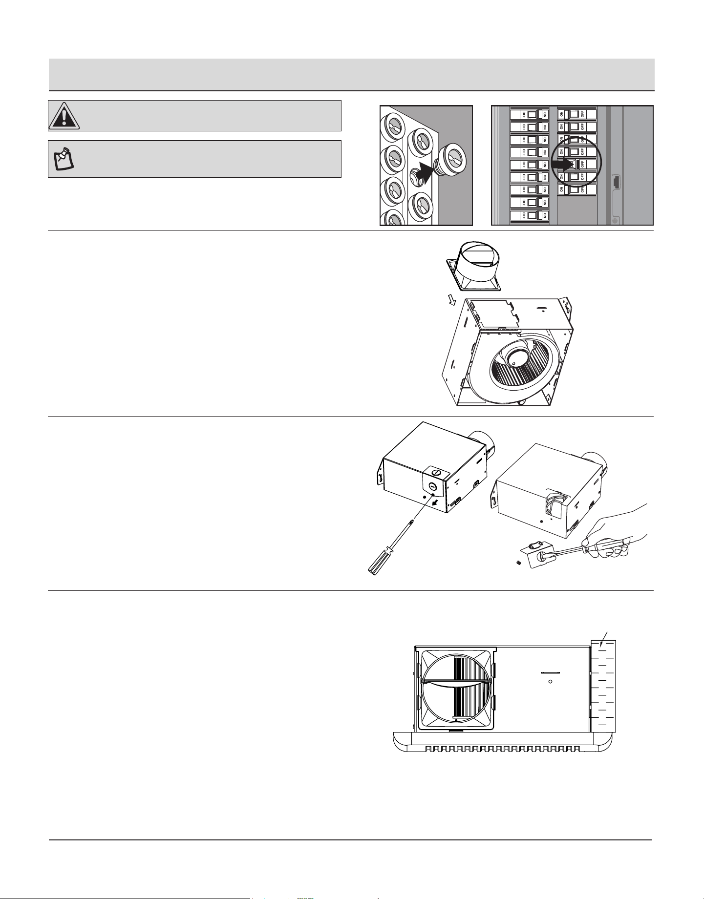
1
Attaching duct connector
Attach duct connector to the fan housing as shown in the
drawing.
2
Remove the wiring box knockout
Remove the wiring box cover from the fan housing with a
Phillips head screwdriver (not included). Remove the wiring
knockout from the wiring box cover with a athead screw-
driver (not included).
3
Fan housing placement
Joist or
wall stud
Place the fan housing next to a ceiling joist or wall stud. The
fan housing should be level and perpendicular to the joist or
stud.
7
HAMPTONBAY.COM
Please contact 1-855-HD-HAMPTON for further assistance.
Installation - New Construction (continued)
4
Mount the fan housing
Ceiling joist
Mount the fan housing to the joist using two long wood screws
(D) where indicated.
5
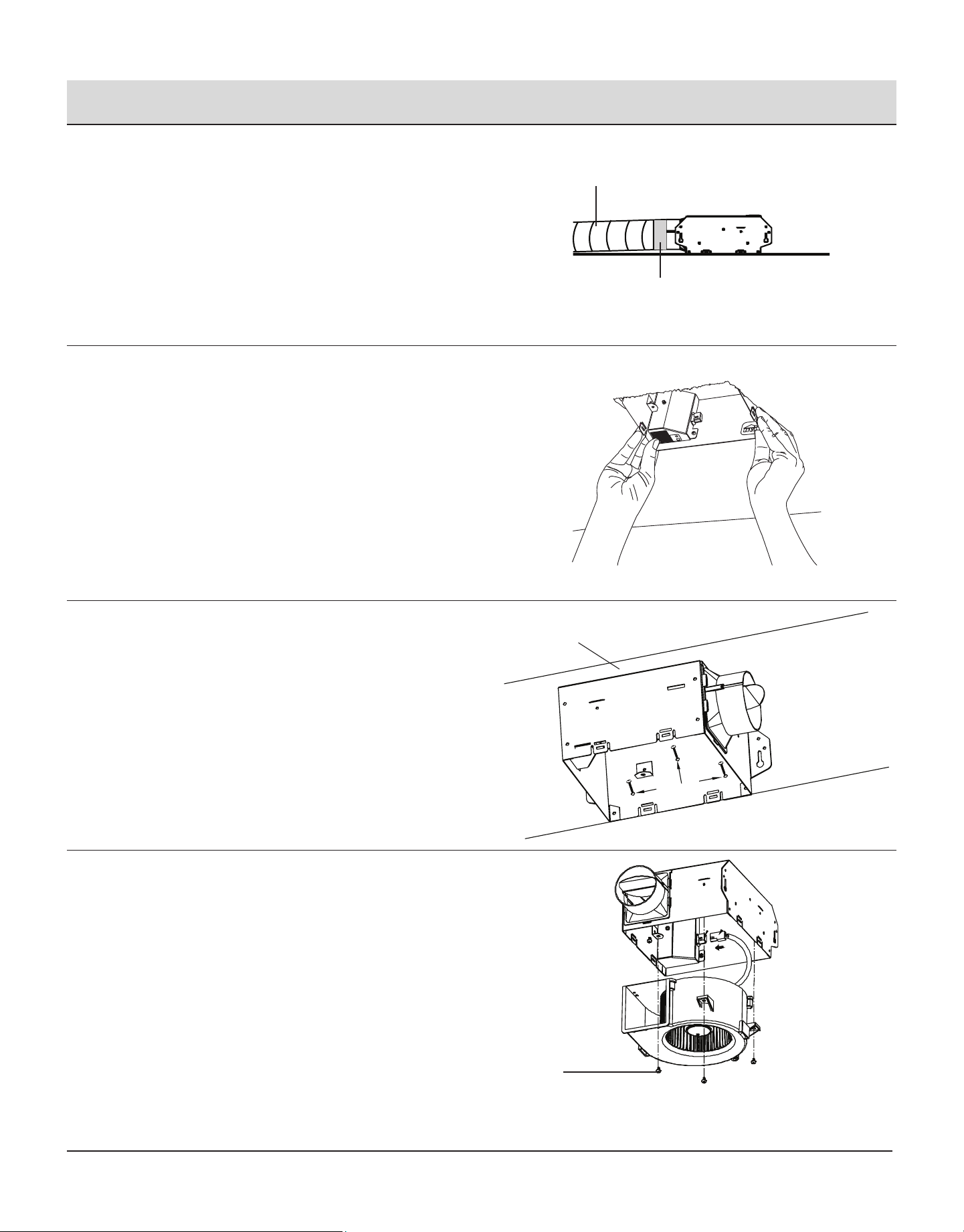
Connect house and fan wires
Black (Live)
White (Neutral)
Green (Ground)
Wiring
plate
Fan
House
wires
Quick
connector
Product
wires
Pull the wire through the hole and into the junction box (not
included). Using a quick connector, secure 120 VAC house
wiring from the wall switch to the fan as shown in the wiring
diagram on the right. 14AWG is the smallest conductor that
shall be used for branch-circuit wiring.
NOTE: Unit can be mounted in a ceiling or wall.
CAUTION: If the electrical wires do not match the colors listed,
you must determine what each house wire represents before
connecting. You may need to consult an electrical contractor to
determine safely.
Push the wires back through the hole. Reattach the wiring box
cover.
6
Install the duct
Ceiling
3 in. duct
Duct tape
or clamp
Install a circular 3 in. duct (not included) and secure it with
duct tape or clamps (neither included).
Finish ceiling work. The ceiling hole should be aligned with
the edge of the fan housing.
7
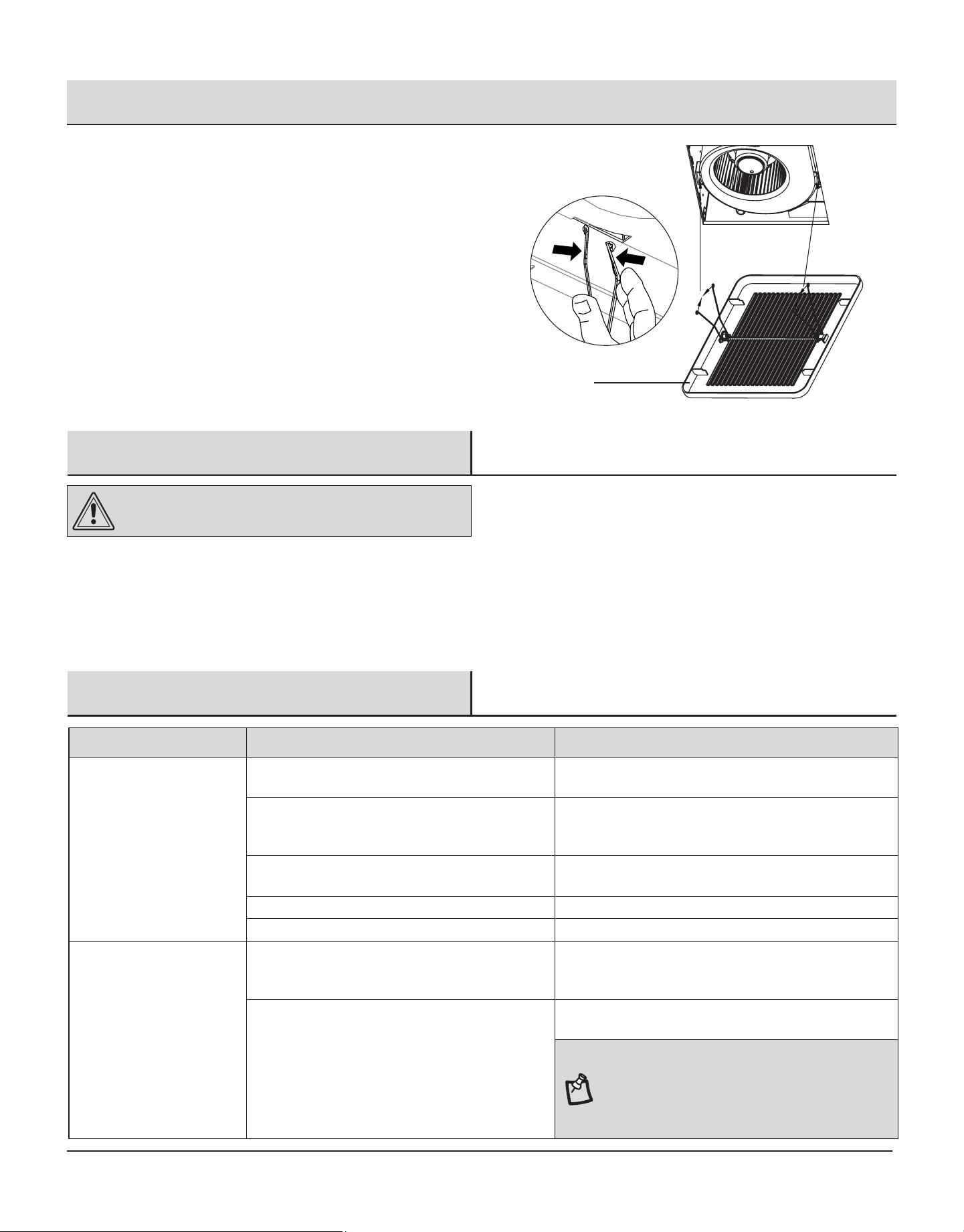
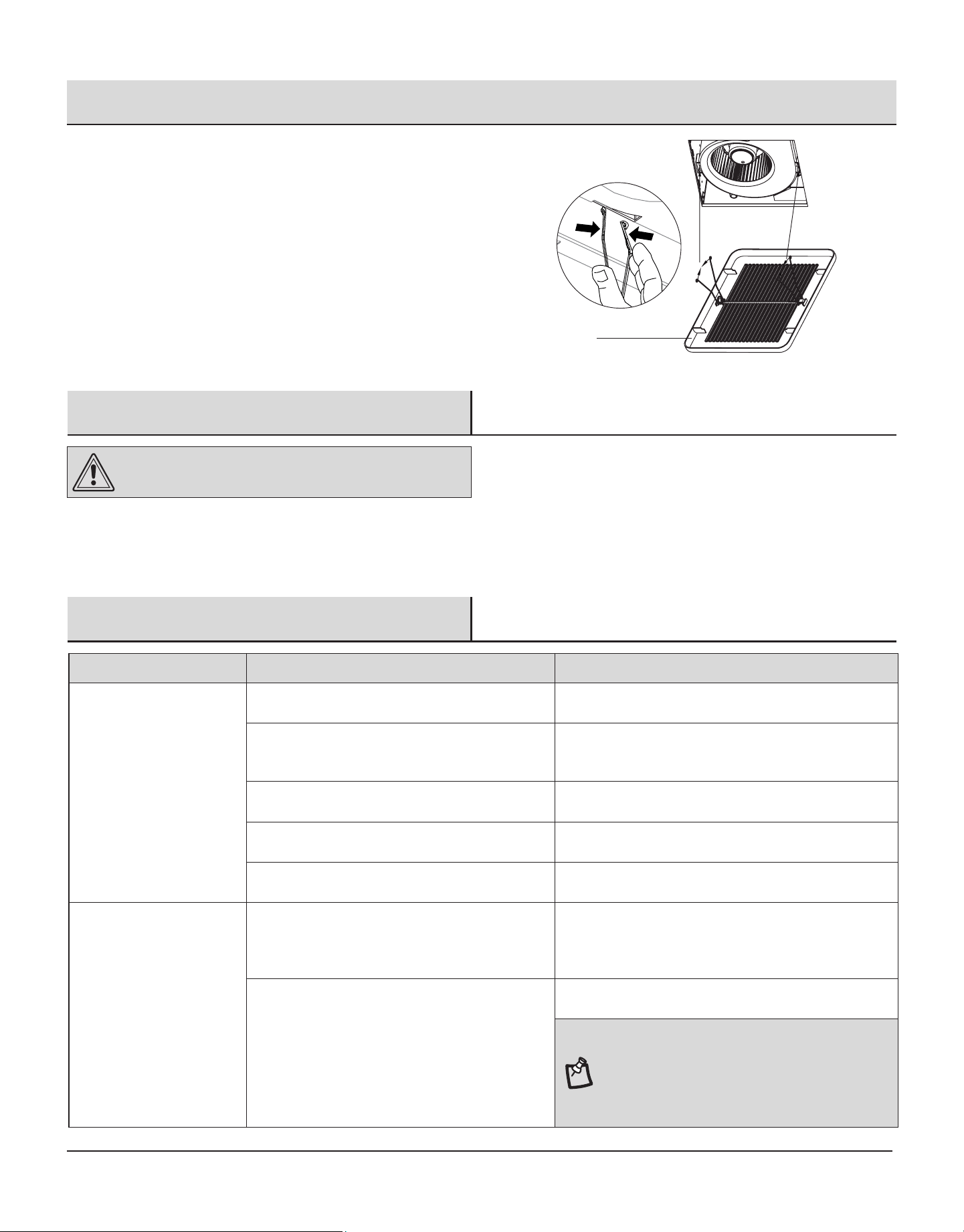
Install the grille
Pinch the mounting springs on the grille (B) and insert them into
the narrow rectangular slots inside the fan. Push the grille (B) up
toward ceiling.
Turn on electricity at the breaker box after nishing installation.
B
8
Installation - Existing Construction
CAUTION: Turn o electricity at breaker box before
beginning installation. Review all safety precautions.
1
Remove the existing fan
Remove the old fan from the ceiling.
2
Measure the ceiling opening
Measure the opening to assure it is large enough to accom-
modate the new fan body (A) (7.50 in. x 7.25 in.).
NOTE: 7.25 inch side of the opening should be ush with the joist.
3
Enlarge the opening (optional)
7.50"
7.25
"
If this fan is not replacing an old fan, be sure to cut a
7.50 in. x 7.25 in. opening for the fan body (A).
MAKE SURE THE 7.25 IN. SIDE OF THE OPENING IS FLUSH
WITH THE JOIST FOR INSTALLATION FROM BELOW.
9
HAMPTONBAY.COM
Please contact 1-855-HD-HAMPTON for further assistance.
Installation - Existing Construction (continued)
4
Attaching duct connector
Attach duct connector to the fan housing as shown in the
drawing.
5
Remove the fan motor assembly
1
Remove the three screws (1) that hold the fan motor assembly
in place. Remove the fan motor assembly from the fan housing.
Unplug the fan power unit.
6
Remove the wiring box knockout
Remove the wiring box cover from the fan housing. Remove
the wiring knockout from the wiring box cover with a athead
screwdriver (not included).
7
Connect house and fan wires
Black (Live)
White (Neutral)
Green (Ground)
Wiring
plate
Fan
House
wires
Quick
connector
Product
wires
Pull the wire through the hole and into the junction box (not
included). Using a quick connector, secure 120 VAC house
wiring from the wall switch to the fan as shown in the wiring
diagram on the right. 14AWG is the smallest conductor that
shall be used for branch-circuit wiring.
NOTE: Unit can be mounted in a ceiling or wall.
CAUTION: If the electrical wires do not match the colors listed,
you must determine what each house wire represents before
connecting. You may need to consult an electrical contractor to
determine safely.
Push the wires back through the hole. Reattach the wiring box
cover.
10
Installation - Existing Construction (continued)
8
Installing the duct
Ceiling
3 in. duct
Duct tape
or clamp
Install a circular 3 in. duct (not included) and secure it with
duct tape or clamps (neither included).
Finish ceiling work. The ceiling hole should be aligned with
the edge of the fan housing.
9
Insert the fan housing
Insert the fan housing through the existing hole in the ceiling.
The fan housing should be level and perpendicular to the joist
or stud.
10
Mount the fan housing to the joist
Ceiling joist
Mount the fan housing to the joist using three long wood
screws (D) where indicated by arrows inside the fan housing.
11
Reattach the motor assembly
Plug the motor assembly back into the power unit. Reattach
the motor assembly using the three screws (1) removed in
step 4.
1
11
HAMPTONBAY.COM
Please contact 1-855-HD-HAMPTON for further assistance.
12
Install the grille
Pinch the mounting springs on the grille (B) and insert them
into the narrow rectangular slots inside the fan. Push the grille
(B) up toward the ceiling.
Turn on electricity at the breaker box after nishing installation.
Installation - Existing Construction (continued)
B
Troubleshooting
WARNING: Disconnect power supply before servicing.
See SAFETY INFORMATION before proceeding. Routine maintenance should be done at least once a year.
Never use solvents, thinner or harsh chemicals for cleaning the fan.
Do not allow water to enter the motor.
Do not immerse metal parts in water.
Care and Maintenance
Problem Possible Cause
Solution
The fan seems louder than
it should.
The CFM is too great.
Be sure the CFM rating on the fan matches the square
footage of your room.
The damper is damaged or not working properly.
Check the damper to ensure it is opening and closing
properly. If the damper has become damaged, please call
Customer Service.
The bend in the duct is too close to the fan discharge.
Be sure you do not have any sharp bends in the duct closer
than 18 in. to the fan discharge.
The fan discharge is reduced to t a smaller duct. Use the recommended size ducting to reduce fan noise.
The fan body is not attached securely. Be sure the fan is securely attached to the ceiling joists.
The fan is not clearing the
room.
There is insufcient airow intake in the room.
Be sure a door or window is slightly ajar or opened to allow
airow. The fan is not able to draw air out of the room without
enough airow to draw from.
There is insufcient CFM. Be sure the CFM rating on the fan matches the requirements
for your room size.
NOTE: Using a tissue is not the correct method for
determining if the fan is operating properly. If the fan
clears steam from the room within approximately 15
minutes of completeing your shower, then the fan is
operating properly.

12
Questions, problems, missing parts? Before returning to the store,
call Hampton Bay Customer Service
8 a.m. - 7 p.m., EST, Monday-Friday,
9 a.m. - 6 p.m., EST, Saturday
1-855-HD-HAMPTON
HAMPTONBAY.COM
Retain this manual for future use.
13
Artículo #1001-419-054
Modelo #7114-01
GUÍA DE USO Y CUIDADO
VENTILADOR SIN CORTES DE FÁCIL INSTALACIÓN
¿Preguntas, problemas, piezas faltantes? Antes de volver a la tienda,
llame a la sección de Servicio al cliente de Hampton Bay de 8 a.m a 7 p.m., hora
estándar del Este de lunes a viernes y los sábados de 9 a.m. a 6 p.m., hora estándar del Este.
1-855-HD-HAMPTON
HAMPTONBAY.COM
GRACIAS
Le agradecemos por depositar su confianza en Hampton Bay con la compra de este ventilador para baño. Nos esforzamos continuamente por crear
productos de calidad diseñados para mejorar su casa. Visítenos en línea para ver la línea completa de productos disponible para sus necesidades de
mejoras en el hogar. ¡Gracias por elegir Hampton Bay!
14
Índice ............................................................................... 2
Información de seguridad.............................................. 2
Especicaciones del producto ...................................... 3
Instalación común .......................................................... 3
Diagrama del cableado .................................................. 3
Instrucciones para el conector de conexión rápida .................. 3
Garantía ........................................................................... 4
GARANTÍA LIMITADA DE POR VIDA ..........................................4
¿QUÉ ESTÁ CUBIERTO .............................................................4
Antes de la instalación ................................................... 4
Planicación de la instalación ................................................. 4
Herramientas necesarias ........................................................4
Contenido del paquete ............................................................ 5
Instalación en construcciones nuevas ......................... 6
Instalación en construcciones existente ..................... 8
Cuidado y mantenimiento ............................................ 11
Solución de problemas ................................................ 11
Índice
Información de seguridad
Lea y comprenda completamente este manual antes de intentar ensamblar, usar o instalar el producto.
1. Desconecte siempre el suministro de electricidad antes de realizar tareas de mantenimiento en el ventilador, el motor o la caja de unión.
2. Siga todos los códigos de construcción, eléctricos y de seguridad locales, así como también el Código Nacional de Electricidad (NEC, por sus
siglas en inglés) y el de la Administración de Salud y Seguridad Ocupacional (OSHA, por sus siglas en inglés).
3. El suministro de electricidad debe ser de 120 voltios y 60 Hertz.
4. El producto debe conectarse correctamente al cable de puesta a tierra del circuito de suministro.
5. No doble ni pliegue los conductores de fuerza.
6. No utilice este ventilador con dispositivos de control de estado sólido, tales como controles remotos, reguladores de intensidad o algunos tempori-
zadores. Los temporizadores mecánicos no son dispositivos de estado sólido.
7. No instale en un techo con aislamiento superior a R40.
8. Los componentes para conductos se deben instalar en línea recta, con el mínimo de dobleces.
9. El tamaño de los componentes para conductos debe representar el mismo tamaño de la descarga y no se debe reducir. Reducir el tamaño del
conducto podría aumentar el ruido del ventilador.
ADVERTENCIA
PARA REDUCIR EL RIESGO DE INCENDIOS, DESCARGAS ELÉCTRICAS O LESIONES PERSONALES, SIGA LAS SIGUIENTES INSTRUCCIONES:
1. Use esta unidad solo de la manera prevista por el fabricante. Si tiene alguna pregunta, llame a Servicio al Cliente.
2. Antes de reparar o limpiar la unidad, corte la energía en el panel de servicio y bloquee los medios de desconexión del servicio, a n de impedir la
activación accidental de la energía. Cuando no sea posible bloquear los medios de desconexión del servicio, je al panel de servicio un dispositivo
de advertencia que se destaque, como por ejemplo, una etiqueta.
3. El trabajo de instalación y el cableado eléctrico deben ser realizados por personas calicadas, de acuerdo con todos los códigos y normas aplica-
bles, incluida la fabricación con resistencia al fuego.
4. Se necesita una cantidad de aire suciente para que se produzca una combustión apropiada y la extracción de gases a través del tiro (chimenea) del
equipo de combustión para evitar que haya corrientes de aire inversas. Siga las pautas de seguridad del fabricante del equipo de calefacción, y las
normas de seguridad publicadas por la Asociación Nacional de Protección contra Incendios (NFPA, por sus siglas en inglés), la Sociedad Americana de
Ingenieros para Calefacción, Refrigeración y Aire Acondicionado (ASHRAE, por sus siglas en inglés) y las autoridades de código local.
5. Cuando corte o taladre una pared o techo, no dañe el cableado eléctrico ni otras instalaciones ocultas.
6. Los ventiladores con conductos siempre deben contar con una salida al exterior.
7. Si esta unidad se instalará en una bañera o ducha, debe estar marcada como apta para la aplicación y se debe conectar a un circuito de falla de
puesta a tierra (GFCI, por sus siglas en inglés).
PRECAUCIÓN
1. Solamente para usos de ventilaciones generales. No lo use para extraer materiales ni vapores peligrosos o explosivos.
2. No utilizar en áreas de cocción.
3. Para reducir el riesgo de lesiones a personas, instale el ventilador a por lo menos 2,5 m sobre el piso.
15
HAMPTONBAY.COM
Por favor, póngase en contacto con 1-855-HD-HAMPTON para obtener más ayuda.
Especicaciones del Producto
Instalación Común
Diagrama del Cableado
ESPECIFICACIONES ESPECIFICACIONES
Flujo de aire: 50 CFM Consumo de energía 8.0 vatios
120 V, 60 Hz Peso: 3.65 lb
Diámetro del conducto: 7,62 cm
Dimensiones requeridas para la apertura del techo:
19,05 cm A x 18,79 cm L x 10,16 cm de alto
Potencia de sonido: Potencia del sonido: 1,0 sonios
INSTRUCCIONES PARA EL CONECTOR DE
CONEXIÓN RÁPIDA
Se debe vender únicamente con las instrucciones de instalación.
ADVERTENCIA: El cableado debe cumplir con todos los códigos eléctri-
cos aplicables. Apague el suministro eléctrico antes de instalar o retirar los
conectores.
ADVERTENCIA: SOLO DE COBRE A COBRE. No usar conductores de
aluminio.
PRECAUCIÓN: La pieza accesoria (conector de conexión rápida) debe
cumplir con las instrucciones de instalación a continuación.
NOTA: El conector se puede volver a usar en conductores sólidos del
mismo calibre o menor. No use el conector en conductores trenzados.
• Pele los cables 0,95 cm a 1,27 cm
• Sujete el conductor firmemente
y pase el extremo pelado del
conductor por el puerto abierto
del conector. Use solo un con-
ductor por puerto.
• Verifique que el extremo pelado
del conductor esté insertado
completamente al fondo del
conector.
NOTA: Información importante sobre el conductor. La clasicación de
temperatura máxima es 105 ºC (221 ºF). Clasicación de voltaje de
600 V como máximo y 1000 voltios como máximo para cables para
edicios y 1000 voltios como máximo en lámparas y letreros. El rango
de conductor aceptable incluye: Sólido: AWG de 12 a 18.
El conducto que va desde el ventilador hasta el
exterior tiene un gran efecto en el ujo de aire,
ruido y consumo de energía del ventilador. Use el
rutado de conductos más corto directo posible
para un mejor rendimiento y evite instalar el
ventilador con conductos más pequeños que los
recomendados. El aislamiento alrededor de los
conductos puede reducir la pérdida de energía e
inhibir la proliferación de moho. Los ventiladores
instalados con conductos existentes pueden
impedir que se alcancen los ujos de aire
deseados.
16
GARANTÍA LIMITADA DE POR VIDA
¿QUÉ ESTÁ CUBIERTO
Si este producto falla debido a un defecto en el material o la mano de obra en cualquier momento durante los primeros CINCO años de poseerlo, el fab-
ricante lo reemplazará sin cargos y con el franqueo pagado a su discreción. Esta garantía no cubre productos que hayan sufrido abusos, modicaciones,
daños, uso indebido, cortes o desgaste. Esta garantía no cubre el uso con nes comerciales. Use solo piezas de repuesto con garantía genuinas sumi-
nistradas por el fabricante para reparar el ventilador. La utilización de piezas de repuesto no genuinas anulará la garantía. El fabricante RECHAZA todas
las demás garantías expresas o implícitas, incluyendo todas las garantías de comerciabilidad e idoneidad para un n en especial. Debido a que algunos
estados no permiten exclusiones o limitaciones en una garantía implícita, las exclusiones y limitaciones anteriores pueden no aplicarse. Esta garantía le
otorga derechos legales especícos, pero podría tener también otros derechos que varían según el estado.
Esta garantía se limita solo al reemplazo de piezas defectuosas. Quedan excluidos los cargos y/o daños por mano de obra incurridos durante la instalación,
reparación o reemplazo, además de los daños incidentales o resultantes relacionados con estos. Cualquier daño a este producto como resultado de neg-
ligencia, uso indebido, accidente, instalación inadecuada o cualquier otro uso distinto al descrito en el presente ANULARÁ ESTA GARANTÍA. Los costos de
envío por cualquier devolución del producto como parte de una reclamación de garantía estarán a cargo del cliente.
Llame al Equipo de Servicio al Cliente al 1-885-HDHAMPTON o visite www.HAMPTONBAY.com.
Garantía
Antes de la instalación
PLANIFICACIÓN DE LA INSTALACIÓN
Antes de comenzar a ensamblar el producto, asegúrese de tener todas las piezas. Compare las piezas con la lista del contenido del paquete y los
aditamentos. No intente ensamblar el producto si falta alguna pieza o si estas están dañadas.
ADVERTENCIA: Desconecte la electricidad en la caja del
interruptor de circuito antes de comenzar la instalación.
Retire con cuidado la unidad de la caja.
Revise el área situada sobre la ubicación de la instalación para asegurarse de que el cableado se extienda hasta la ubicación planicada, que los
componentes para conductos se puedan instalar y que el área sea apropiada para lograr la ventilación adecuada..
Revise los componentes para conductos y el cableado antes de continuar con la instalación.
Antes de instalar, asegúrese de dejar un acceso para revisiones y tareas de mantenimiento futuras en un lugar que no interera con el trabajo de instalación.
Es posible que necesite la ayuda de otra persona para instalar este ventilador; una persona en el ático y otra en la habitación.
NOTA: La instalación puede variar según la forma en que se instaló
el ventilador para baño anterior. Los suministros necesarios para la
instalación del ventilador para baño no se incluyen en su totalidad.
Sin embargo, estas bombillas están disponibles en las tiendas de
artículos para el hogar y en las ferreterías de su zona.
HERRAMIENTAS NECESARIAS (no incluido)
Martillo
de uñas
Brocas para
taladro
Destornillador
de cabeza
plana
Cinta
aislante
Destornillador
Phillips
Cuchillo
para uso
general
Taladro
eléctrico

17
HAMPTONBAY.COM
Por favor, póngase en contacto con 1-855-HD-HAMPTON para obtener más ayuda.
Antes de la Instalación
CONTENIDO DEL PAQUETE
Parte Descripción Cantidad
A Cuerpo del ventilador 1
B Rejilla 1
C Conector de conducto 1
D
Tornillos de madera largos
(ø4x25mm)
3
A
B
C
D
18
Instalación en Construcciones Nuevas
PRECAUCIÓN: Asegúrese de que la alimentación esté
desconectada en el panel de servicio antes de comen-
zar la instalación.
NOTA: Se puede instalar en un techo o pared.
1
Conexión del conector del conducto
Conecte el conector del conducto a la carcasa del ventilador
como se muestra en el dibujo.
2
Retire la cubierta de la caja del cableado.
Retire la cubierta de la caja de conexiones de la carcasa
del ventilador con un destornillador de cabeza Phillips (no
incluido). Quite el knockout del cableado de la cubierta de la
caja de cableado con un destornillador de cabeza plana (no
incluido).
3
Colocación de la carcasa del ventilador
Espárrago
viga o pared
Coloque la carcasa del ventilador junto a una vigueta de techo
o un montante de pared. La carcasa del ventilador debe estar al
nivel de la vigueta o del montante y ser perpendicular a estos.
19
HAMPTONBAY.COM
Por favor, póngase en contacto con 1-855-HD-HAMPTON para obtener más ayuda.
Instalación en Construcciones Nuevas (continuado)
B
4
Montaje de la carcasa del ventilador
Vigueta del techo
Monte la carcasa del ventilador a la vigueta usando dos tornillos
de madera largos (D) donde se indique.
5
Conecte los cables de la casa y del
ventilador
Placa de
cableado
Ventilador
Cables
casa
Cables de
producto
Conector
rápido
Negro (vivo)
Blanco (Neutro)
Verde (Tierra)
Jale el conductor a través del oricio y en la caja de unión (no
incluida). Utilizando un conector rápido, asegure el cableado de
la casa de 120VAC desde el interruptor de pared al ventilador
como se muestra en el diagrama de cableado de la derecha.
El conductor de 14 AWG es el más pequeño que se usará para el
cableado del circuito de derivación.
NOTA: Se puede instalar en un techo o pared.
PRECAUCIÓN: Si los conductores eléctricos no combinan con los col-
ores enumerados, debe determinar qué representa cada conductor
de la casa antes de la conexión. Es posible que necesite consultar a
un electricista para tomar una decisión que no implique peligros.
Empuje los cables a través del agujero. Vuelva a colocar la
cubierta de la caja de conexiones.
6
Instale el conducto
Techo
3 pulg. conducto
La cinta adhesiva
o una abrazadera
Instale un conducto circular de 7,62 cm (no incluido) y fíjelo
con cinta aislante o abrazaderas (tampoco incluidas).
Finalice el trabajo en el techo. El oricio en el techo debe
estar alineado con el borde de la carcasa del ventilador.
7
Instale la parrilla
Apriete los resortes de montaje de la rejilla (B) e introdúzcalos
en las ranuras rectangulares estrechas dentro del ventilador.
Presione la rejilla (B) hacia el techo.
Conecte la electricidad en la caja del interruptor después de
nalizar la instalación.
20
Instalación en construcciones existente
PRECAUCIÓN: Desconecte la electricidad en la caja
del interruptor de circuito antes de comenzar la insta-
lación. Revise todas las precauciones de seguridad.
1
Retire el ventilador existente
Retire el ventilador antiguo del techo.
2
Mida la abertura del techo
Mida la abertura para asegurarse de que es lo sucientemente
grande como para ubicar el nuevo cuerpo del ventilador (A)
(19,05 cm x 18,41 cm).
NOTA: El borde de 18 41 cm de la abertura debe estar al ras del
borde de la vigueta.
3
Agrande la abertura (opcional)
19,05cm
18,41 cm
Si el ventilador no es para reemplazar un ventilador antiguo,
asegúrese de cortar una abertura de 19,05 cm x 18,41 cm
para el cuerpo del ventilador (A).
ASEGÚRESE DE QUE EL BORDE DE 18,41 CM DE LA ABERTURA
ESTÉ AL RAS DE LA VIGUETA PARA LA INSTALACIÓN DESDE
ABAJO.
21
HAMPTONBAY.COM
Por favor, póngase en contacto con 1-855-HD-HAMPTON para obtener más ayuda.
Instalación en construcciones existente (continuado)
4
Conexión del conector del conducto
Conecte el conector del conducto a la carcasa del ventilador
como se muestra en el dibujo.
5
Retire el ensamble del motor del ventilador
1
Retire los tres tornillos (1) que sostienen el ensamble del motor
del ventilador en su lugar. Retire el ensamble del motor del
ventilador de la carcasa del ventilador. Desenchufe la unidad
de tomacorriente del ventilador.
6
Retire la cubierta de la caja del cableado.
Retire la cubierta de la caja de conexiones de la carcasa
del ventilador con un destornillador de cabeza Phillips (no
incluido). Quite el knockout del cableado de la cubierta de la
caja de cableado con un destornillador de cabeza plana (no
incluido).
6
Conecte los cables de la casa y del
ventilador
Placa de
cableado
Ventilador
Negro (vivo)
Blanco (Neutro)
Verde (Tierra)
Cables de
producto
Conector
rápido
Cables
casa
Jale el conductor a través del oricio y en la caja de unión (no
incluida). Utilizando un conector rápido, asegure el cableado de
la casa de 120VAC desde el interruptor de pared al ventilador
como se muestra en el diagrama de cableado de la derecha.
El conductor de 14 AWG es el más pequeño que se usará para el
cableado del circuito de derivación.
NOTA: Se puede instalar en un techo o pared.
PRECAUCIÓN: Si los conductores eléctricos no combinan con los col-
ores enumerados, debe determinar qué representa cada conductor
de la casa antes de la conexión. Es posible que necesite consultar a
un electricista para tomar una decisión que no implique peligros.
Empuje los cables a través del agujero. Vuelva a colocar la
cubierta de la caja de conexiones.
22
Instalación en construcciones existente (continuado)
8
Instale el conducto
Techo
3 pulg. conducto
La cinta adhesiva
o una abrazadera
Instale un conducto circular de 7,62 cm (no incluido) y fíjelo
con cinta aislante o abrazaderas (tampoco incluidas).
Finalice el trabajo en el techo. El oricio en el techo debe
estar alineado con el borde de la carcasa del ventilador.
9
Inserte la carcasa del ventilador
Inserte la carcasa del ventilador a través del oricio existente
en el techo. La carcasa del ventilador debe estar al nivel de la
vigueta o del montante y ser perpendicular a estos.
10
Montaje de la carcasa del ventilador
Vigueta del techo
Montar la carcasa del ventilador en la vigueta con tres tornillos de
madera largos (D) donde se indican mediante echas dentro de la
carcasa del ventilador.
11
Coloque nuevamente el ensamble del motor
Enchufe el ensamble del motor a la unidad del tomacorriente.
Vuelva a colocar el ensamble del motor utilizando los tres
tornillos retirados en el paso 4.
1
23
HAMPTONBAY.COM
Por favor, póngase en contacto con 1-855-HD-HAMPTON para obtener más ayuda.
Solución De Problemas
ADVERTENCIA: Desconecte el suministro de electrici-
dad antes de realizar tareas de mantenimiento.
Vea la INFORMACIÓN DE SEGURIDAD antes de proceder. Se debe realizar mantenimiento de rutina al menos una vez al año.
Nunca use solventes, disolventes o químicos agresivos para limpiar el ventilador.
No permita que entre agua en el motor.
No sumerja piezas de metal en agua.
Cuidado y Mantenimiento
Problema Causa Posible
Solución
El ventilador hace más
ruido de lo que debería.
Os m
3
/min son demasiados.
Asegúrese de que la clasicación de m
3
/min en el ventilador
coincida con los metros cuadrados de su habitación.
El regulador de tiro no funciona en forma adecuada o
está dañado.
Revise el regulador de tiro para garantizar que se abra y
cierre correctamente. Si el regulador de tiro se ha dañado,
llame al Servicio al Cliente.
El pliegue del conducto está demasiado cerca de la
descarga del ventilador.
Asegúrese de que no haya bordes losos en el conducto a
menos de 45,72 cm de la descarga del ventilador.
La descarga del ventilador se ha reducido para adap-
tarse a un conducto de menor tamaño.
Utilice los conductos de tamaño recomendado para reducir el
sonido del ventilador.
El cuerpo del ventilador no está bien ajustado.
Asegúrese de que el ventilador esté rmemente ajustado a las
viguetas del techo.
El ventilador no ventila la
habitación.
El ujo de entrada de aire dentro de la habitación es
inadecuado.
Asegúrese de que una puerta o ventana quede levemente
entreabierta o abierta para permitir el ujo de aire. El ventilador
no puede expulsar el aire de la habitación sin un ujo de aire
adecuado.
El nivel de m
3
/min. es insuciente. Asegúrese de que la clasicación de m
3
/min. del ventilador
coincida con los requisitos del tamaño de su habitación.
NOTA: Utilizar una tela suave no es el método correcto
para determinar si el ventilador funciona correcta-
mente. Si el ventilador elimina el vapor de la habitación
en aproximadamente 15 minutos de haber terminado
de bañarse, entonces el ventilador funciona correcta-
mente.
Instalación en construcciones existente (continuado)
12
Instale la parrilla
Apriete los resortes de montaje de la rejilla (B) e introdúzcalos
en las ranuras rectangulares estrechas dentro del ventilador.
Presione la rejilla (B) hacia el techo.
Conecte la electricidad en la caja del interruptor después de
nalizar la instalación.
B

24
¿Preguntas, problemas, piezas faltantes? Antes de volver a la tienda,
llame a la sección de Servicio al cliente de Hampton Bay de 8 a.m a 7 p.m., hora
estándar del Este de lunes a viernes y los sábados de 9 a.m. a 6 p.m., hora estándar del Este.
1-855-HD-HAMPTON
HAMPTONBAY.COM
Conserve este manual para uso futuro.