Bathroom Ventilation
Fan with Light
USER MANUAL
THANK
YOU!
Thank You for Purchasing from
Made in China
NOTE:
To continuously improve its products, reserves the right to
modify this information without prior notification.
For any questions regarding assembly, please watch the video on the
product page or contact our customer service. Our customer service will
Thank you for using products in your home!

USER MANUAL
HOW-TO
Bathroom Ventilation
Fan with Light
CONTENTS
Product Specifications .................................................1
Packing List .........................................................................1
Security Information .....................................................3
Pre-installation Preparation ....................................4
Installation Instruction ................................................7
Care and Cleaning ........................................................11
Troubleshooting ............................................................12
Warranty ............................................................................13
1 2
SECTION A
Product Specifications
1.
2.
3.
4.
5.
6.
7.
Always disconnect the power supply or junction box before
performing any maintenance on the fan or motor.
The optimal voltage for use of the product is 120 volts, 60 Hz.
The product must be properly connected to the power
circuit.
Do not bend or knot the power cord.
Do not install on a ceiling with insulation greater than R40.
Install the vent pipe in a straight line to minimize any bends
in the pipe.
Ensure that the vent pipe size matches the fan vent size
exactly and is not reduced, as a smaller vent duct may result
in increased fan noise.
1.
3.
4.
For general ventilation use only. Do not use for venting haz-
ardous or explosive materials and vapors.
Not intended for use in cooking areas.
To minimize the risk of injury, install the fan at a height of at
least 7 feet (2.1 meters) above the floor.
Important Safety Information
Before attempting assembly, read and understand the entire
manual before operating or installing the product.
Warning: To minimize the risk of fire, electric shock, or personal
injury, please follow these precautions.
SECTION B
Package List
Product Specifications
Airflow: 111 CFM
Motor power consumption: 45W
Noise: 37 dB
LED light color (CCT): 6000K Cool White
Voltage: 100-120 V, 50/60 Hz LED Power consumption: 10.8W
Tube diameter: 4 In
LED light brightness: 900 Lumens Dimmable
LED life: 30,000 Hours
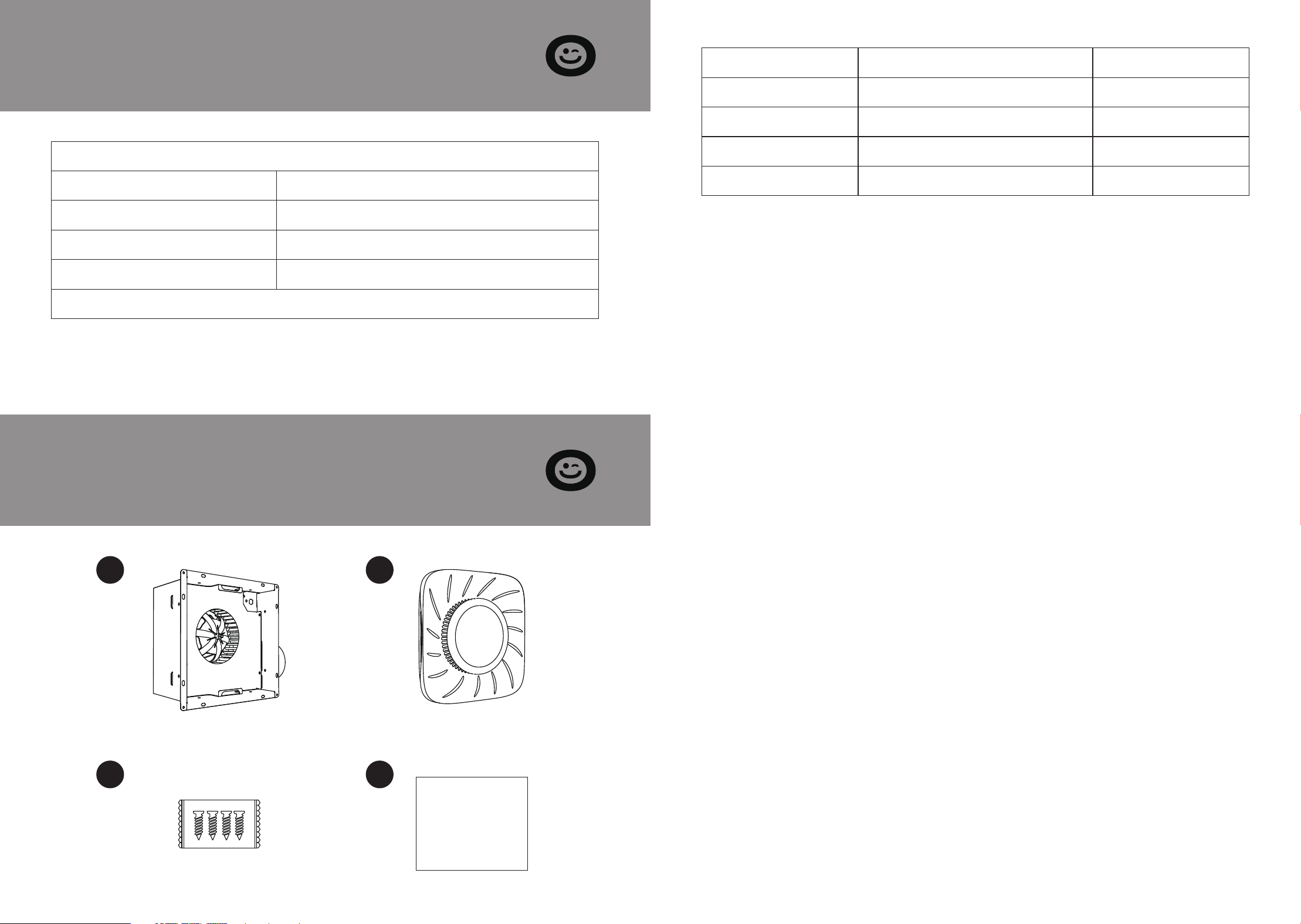
Part Description Quantity
A Fan Cover 1
B Grille / Light 1
C Wood Screws 1
D Paperboard 1
A B
C D

3 4
Operate this device according to the manufacturer’s instructions.
For any questions, contact Customer Service. Before servicing or
cleaning the unit, turn off the power at the service panel and
lock the service disconnect to avoid accidental power-up. If
locking the service disconnect is not possible, attach a promi-
nent warning device (such as a tag) to the service panel.
Installation and electrical wiring must be completed by qualified
professionals, adhering to all relevant codes and standards,
including those for fire-resistant construction.
Duct fans must be vented directly to the outdoors at all times.
If installing the unit over a bathtub or shower, ensure it is
labeled for this application and connected to a branch circuit
protected by a GFCI (ground fault circuit interrupter).
When installing this ventilation fan in a bathtub or shower, posi-
tion it at least 3 feet 3-1/4 inches (1 meter) from the showerhead.
Installing the fan within the shower stall is not recommended
unless this minimum distance can be maintained.
Note: Turn off the power before installing this unit and keep it
off until installation is complete. If the unit does not power on,
please consult the troubleshooting section of the manual.
For further assistance, please contact us via email
SECTION C
Safety Information
Before starting assembly, verify that all parts are present by
checking them against the package contents and hardware lists.
Do not proceed with assembly, installation, or operation if any
parts are missing or damaged. For replacement parts, please
contact us via email.
Estimated Assembly Time: 60 minutes
Tools Required for Assembly (not included): Hammer, Flathead
Screwdriver, Wood Screws, Duct Tape, Phillips Screwdriver, and
either a Utility Knife or Drywall Saw.
Additional Tools Required (not included): Electric Drill and Drill
Bits
Warning: Risk of Electric Shock! Ensure that the power to the
electrical lines in the work area is turned off.
Before removing an existing fan or installing a new one, discon-
nect the fuse or switch off the circuit breaker.
Inspect the area above the installation site to confirm that wiring
can be extended to the location, ductwork can be installed, and
there is adequate space for proper ventilation.
Before beginning installation, inspect the ductwork and wiring.
Ensure that access for future inspection and maintenance is
prepared in a location that will not obstruct the installation
process.
You may require assistance from a second person to install this
fan.
Installation procedures may vary based on the previous setup.
Note that not all supplies needed for installation are included,
but most can be obtained from your local home improvement
or hardware store.
SECTION D
Pre-assembly Preparation
5 6
1.
2.
3.
Strip the wire 3/8"- 1/2".
Hold the wire securely and insert the stripped end into the
connector opening. Use only one wire per port.
Ensure that the stripped end of the wire is fully inserted into
the back of the connector.
Caution: The maximum temperature rating for the wiring is
221°F (105°C). The wire is rated for 600V maximum in building
wiring and 1,000V maximum for signs and light fixtures. Use
only 12-18 AWG solid copper wire.
Dimensions
Ceiling Opening (4) Ceiling Opening (W) Ceiling Opening (W)
10.236 In. 9.45 In. 7.1 In.
Housing Size (L) Housing Size (W) Housing Size (W)
7-1/2 In. 7-1/4 In. 5-3/4 In.
Ensure all wiring connections are complete to achieve full func-
tionality. Avoid using metal wall plates with switches.
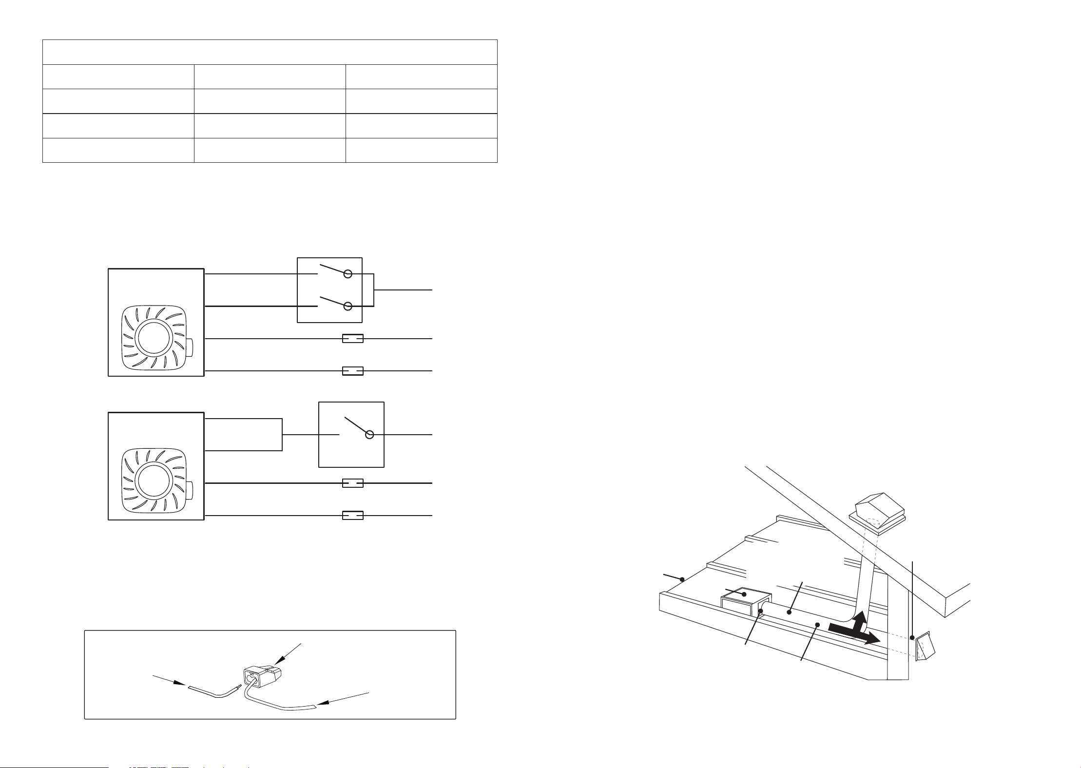
Wiring Installation
Typical Installation
Note: Ensure that the accessories (quick connectors) adhere to
the provided installation instructions.
Note: Connectors may be reused on solid wire of the same
diameter or smaller. Do not reuse connectors on stranded wire.
The ducting from the fan to the exterior of the building greatly
affects airflow, noise, and energy efficiency. For optimal perfor-
mance, use the shortest and straightest ducting possible and
avoid using ducts with a diameter smaller than recommended
for connecting the fan.
FAN
Brown LED
Off
L
N
PE
OnBlack FAN
White
Green
Brown LED
Black FAN
White
Green
N
L
Off
Off
On
On
PE
FAN
Warning: Ensure all wiring complies with applicable electrical
codes. Always turn off the power before removing or installing
connectors.
Warning: Use only copper wire connections. Do not use alumi-
num wire.
House wires
Proudct wires
Quick connectors
Roof cap
(with built-in
damper)
Caulk
termination
to duct
Wall cap
(with a built-in
damper)
2-3 foot
straight
run before
elbow
Seal any gap
around the
fan housing
Properly insulate
around the fan to
minimize building
heat loss and gain
Fan
housing
Short piece of
flexible duct helps
alignment and
absorbs sound
7 8
Before Installation
Installation of the fan housing in an existing building requires
ducting and electrical circuits at the planned location.
SECTION E
Installation Instructions
Warning: Risk of Electric Shock! Ensure that the power to the
electrical wiring in the work area is turned off. Remove the fuse
or switch off the circuit breaker before removing an existing fan
or installing a new one.
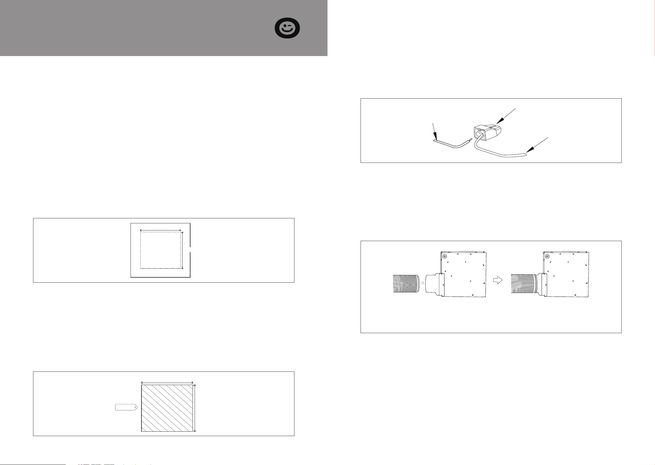
Apply the opening sticker to the installation area, ensuring that
the space is sufficiently large to fit the fan housing
(10.236 in × 9.45 in).
STEP 1:
Please notch 10.236 in×9.45 in according to the size of the paper-
board. (If you need to replace the old fan, please remove the old
fan first to ensure the size of the opening and reinforce the pe-
rimeter of the opening.)
STEP 2:
10.236 in
9.45 in
10.236 in
9.45 in
Hole size
Connect the house wires using the quick connector according to
the reference wiring diagram.
Note: If the wire colors do not match those listed, consult a
licensed electrician to identify each wire's function before con-
necting the fan.
STEP 3:
Attach a 4" round vent pipe to the duct connector on the fan
hood and secure it with duct tape or clips. Ensure the vent duct
outlet is positioned outside the house.
STEP 4:
House wires
Proudct wires
Quick connectors
(Alternatively, install the fan in the ceiling, connect the fixed ventilation
duct and power cord, and then mount the fan body so that its bottom
edge is flush with the ceiling.)
9 10
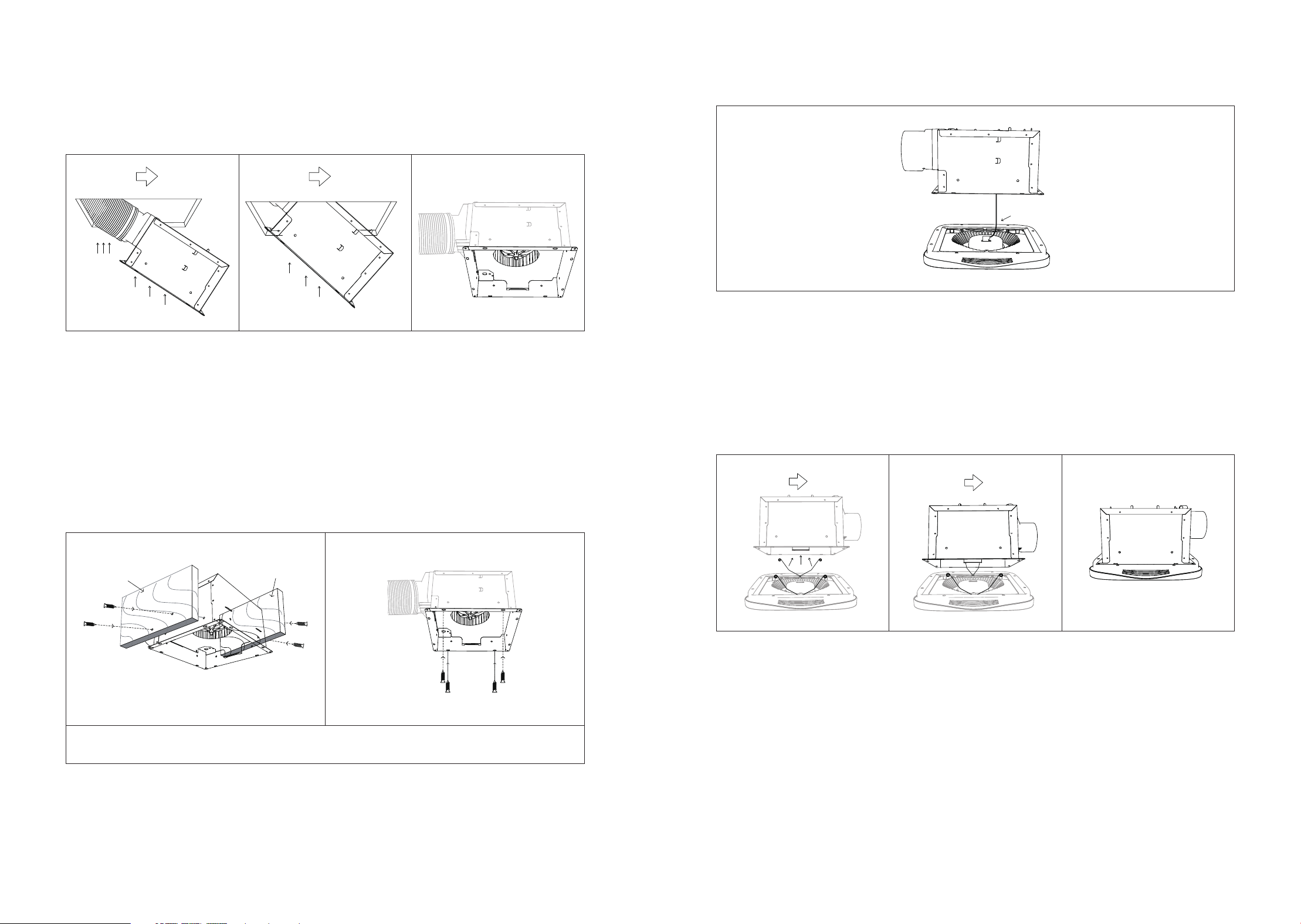
With the wiring and ventilation ducts connected, insert the fan
into the ceiling opening( as shown in the figure below), ensuring
that the bottom edge of the fan is flush with the ceiling.
STEP 5:
To ensure proper operation, clamp the mounting spring and
insert it into the narrow rectangular slot in the fan housing, then
turn on the power to test.
STEP 8:
joist
joist
For the first installation method, secure the fan to the joist (or
wood panel frame) with four wood screws through the holes on
either side of the fan. For the second method, attach the fan to
the ceiling with four wood screws through the holes at the front
of the fan.
STEP 6:
Installation Method 1 Installation Method 2
Note: The fan must be mounted flush with the ceiling; otherwise, the
ril/light mounting springs may not reach the slots inside the fan housing.
Secure the fan to the joist by
inserting screws from inside the fan.
Connect the LED light connector to the fan.
STEP 7:
11 12
SECTION F
Care and Cleaning
Caution: Before cleaning the product, disconnect the power by
turning off the circuit breaker or removing the fuse from the fuse
box. Review the safety information before proceeding. Perform
regular maintenance at least once a year.
SECTION G
Troubleshooting
1.
2.
3.
4.
Do not clean the fan with solvents, thinners, or harsh
chemicals.
Do not allow water to enter the motor.
Do not immerse metal parts in water.
Do not immerse motor parts and lamps in water over 140°F.
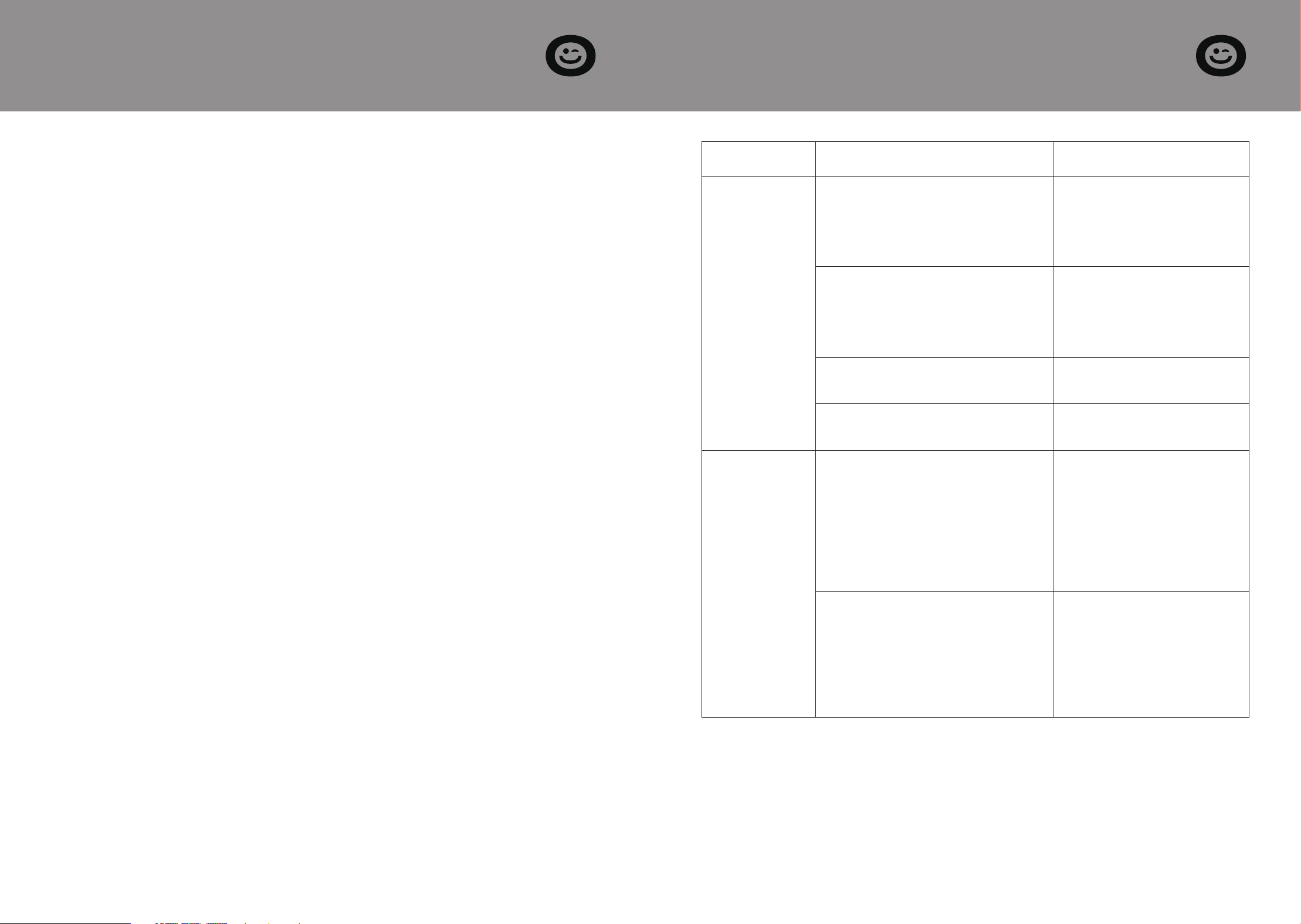
Question Possible Causes Solutions
The fan is
making an
unusually loud
noise.
The damper is either damaged or
not functioning correctly.
Check the damper to make
sure it opens and closes
properly. If the damper is
damaged, call Customer
Service.
The elbow in the ventilation duct
is positioned too close to the
exhaust fan outlet.
Ensure that there are no
bends in the ducts articu-
lated within 18 inches of the
exhaust fan outlet that are
too large in angle
The ventilation ducts are under-
sized.
Use the recommended size
duct to reduce fan noise
The exhaust fan installation is not
securely fastened.
Make sure the fan is secure-
ly attached to the ceiling
Fans do not
eliminate
moisture from
the room.
Insufficient incoming airflow
inside the room
Ensure that doors and
windows are slightly or fully
open to facilitate air circula-
tion in the room. Without
adequate incoming airflow,
the fan will not effectively
draw air in and out of the
room.
Insufficient Airflow
Note: Paper towels are not a
reliable method for checking fan
operation. If the fan effectively
removes steam from the room
within about 15 minutes after a
shower, it is functioning correctly.
Ensure that the fan's CFM
rating is appropriate for the
square footage of your
room.

13 14
SECTION H
Warranty
The VIVOHOME warranty program is our commitment to you.
We are committed to providing you with a high-quality product
that meets your needs and expectations. To demonstrate our
confidence in the durability and performance of our products,
we offer the following warranty.
This warranty program applies to any orders, purchases, receipts,
or use of any products sold by VIVOHOME and is valid for a
period of 1 year from the date of purchase. However, please note
that this warranty period is only valid for the original order. If
you receive a replacement order during the warranty period, it
will not include a separate warranty period.
WARRANTY COVERAGE
This warranty does not cover damage resulting from misuse,
accident, unauthorized modification, or any other circumstances
not directly related to the manufacturing and design of the
product, including but not limited to:
Parts lost during use.
Normal wear and tear of products or parts.
Incorrect installation (such as using the wrong voltage) or
assembly.
Exceeding the bearing capacity of the product.
Use under extremely harsh conditions.
WARRANTY EXCLUSIONS
●
●
●
●
●
SECTION H
Warranty
VIVOHOME will provide technical support, replacement, refund,
or other solutions based on the nature of the issue. If you wish
to return the original package for any reason, please contact us
for confirmation before proceeding. You can expect to receive a
response within 48 hours.
Thank you for choosing VIVOHOME. We are committed to en-
suring the quality and satisfaction of your purchase. If you have
any questions or need assistance, please do not hesitate to con-
tact our customer service team.
If you find any defects that affect the use of the product or if the
product stops working and cannot be repaired during the war-
ranty period, please contact our customer service team at our
email or via Amazon & app’ s direct messaging service as soon as
possible. Provide the following information to expedite the
process:
HOW TO MAKE A WARRANTY CLAIM
Order number
Images and/or videos illustrating the issue
A detailed description of the problem
●
●
●
Improper cleaning or maintenance.
Damage caused by any reason other than the intended use
of the product.
Indirect loss or damage caused by the product.
●
●
●