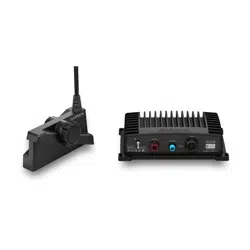
PANOPTIX
™
LIVESCOPE
™
INSTALLATION INSTRUCTIONS
Important Safety Information
WARNING
See the Important Safety and Product Information guide in the chartplotter product box for product warnings
and other important information.
You are responsible for the safe and prudent operation of your vessel. Sonar is a tool that enhances your
awareness of the water beneath your boat. It does not relieve you of the responsibility of observing the water
around your boat as you navigate.
CAUTION
Failure to install and maintain this equipment in accordance with these instructions could result in damage or
injury.
To avoid possible personal injury, always wear safety goggles, ear protection, and a dust mask when drilling,
cutting, or sanding.
NOTICE
When drilling or cutting, always check what is on the opposite side of the surface to avoid damaging the vessel.
To obtain the best performance and to avoid damage to your boat, you must install the Garmin
®
device
according to these instructions.
Read all installation instructions before proceeding with the installation. If you experience difficulty during the
installation, go to support.garmin.com for more information.
Software Update
You must update the Garmin chartplotter software when you install this device. For instructions on updating
the software, see your chartplotter owner's manual at support.garmin.com.
Tools Needed
• Drill
• 4 mm (
5
/
32
in.) and 3.2 mm (
1
/
8
in.) drill bits
• Masking tape
• #2 Phillips screwdriver
• Marine sealant
• 32 mm (1
1
/
4
in.) hole saw (optional)
• Cable ties (optional)
GUID-8ABE5659-3192-4519-8A48-66421E004620 v5March 2021
Mounting Considerations
• You must angle the transducer correctly for your selected mode to work properly.
• You must install the sonar module in a location with adequate ventilation where it will not be exposed to
extreme temperatures.
• You should mount the transducer in a location where it will not be jarred when launching, hauling, or storing.
• You should mount the transducer in a location where it is not behind strakes, struts, fittings, water intake or
discharge ports, thru-hull transducers, or anything that creates air bubbles or causes the water to become
turbulent. Turbulent water may interfere with the sonar beam.
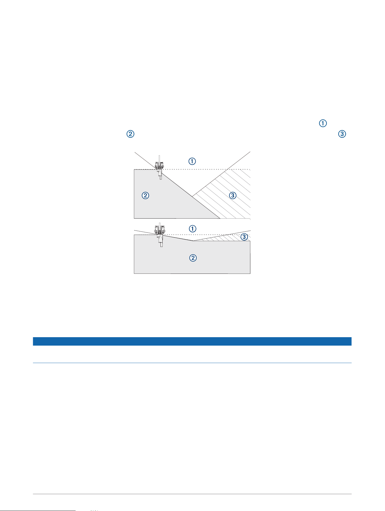
• You should mount the transducer as close to the center line of the boat as possible.
•
When mounted farther from the center of the transom, a greater deadrise can cause the boat hull to
interfere with the sonar beam , and can cause inconsistent detection on the opposite side of the boat .
The transducer is shown from behind.
• On single-drive vessels, you must not mount the transducer in the path of the propeller.
• On twin-drive vessels, you should mount the transducer between the drives, if possible.
• You should mount the sonar module in a location where the LEDs are visible, where the cables can be
connected, and where the device will not be submerged.
Cable Considerations
NOTICE
Zip ties and cable clamps can over-tighten and damage or break the cable, or cause cable fatigue due to
repeated rotation of the motor.
You should use black electrical tape to secure the cable above and below the rotating joint. If you secure the
cable with zip ties, do not over-tighten the zip ties.
You should secure the cable above and below the pivot joint of your trolling motor.
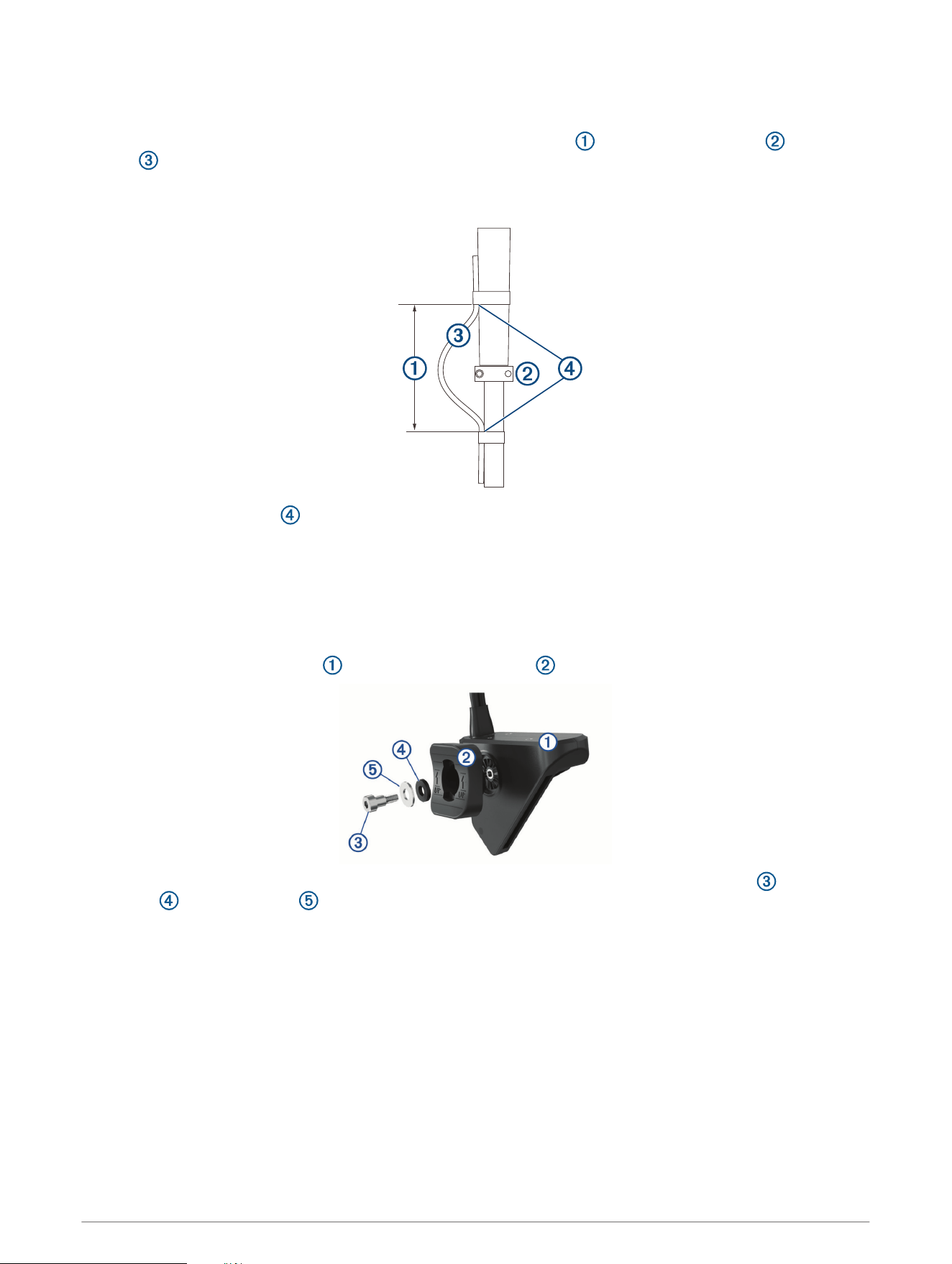
You should create a service loop at least 25 cm (10 in.) long in the cable, with the rotating joint centered on the
loop.
2
Routing the Transducer Cable
You should test-fit the transducer and cable before installation.
1 Allow a loose gap of at least 10 cm ( 4 in.) above and 10 cm (4 in.) below the rotating joint to create a
loop in the cable. The loop must be large enough to allow full rotation of the transducer in both
directions. Allow a minimum of 25 cm (10 in.) of cable to cover the 20 cm (8 in.) section between mounting
points.
2 Use black electrical tape to secure the transducer cable to the shaft.
3 Test the full rotation of the trolling motor to ensure the cable clears the rotating joint and is not pulled tight
due to tension during rotation.
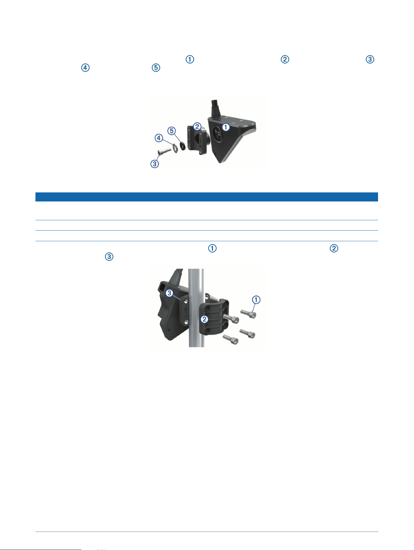
Installing the Transducer on a Trolling Motor
Assembling the Trolling Motor Barrel Mount Hardware
1 Align the top of the transducer with the top of the bracket .
2 Using the included hex wrench, attach the bracket to the transducer with the shoulder screw , rubber
washer , and flat washer .
NOTE: You must fully tighten the mount to the transducer. The recommended torque applied to the shoulder
screw is 2.5 lb-ft. (3.4 N-m).
3
Installing the Transducer on a Trolling Motor
NOTICE
You must secure the transducer cable to the shaft or other secure location during installation. Damage to the
transducer cable wires or cable jacket can cause transducer failure.
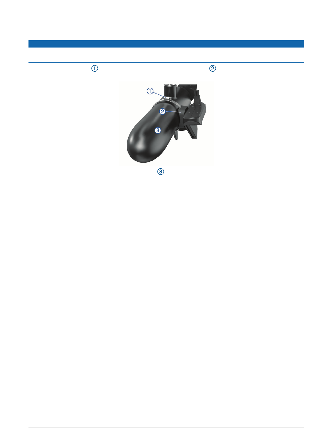
1 Insert the hose clamp through the slot on the trolling motor mount until equal lengths extend on both
sides of the mount.
2 Secure the hose clamp around the trolling motor .
NOTE: Do not rotate the transducer.
3 Secure the transducer cable to the motor shaft or other secure location.
4 Route the transducer cable to the installation location of the sonar module while taking these precautions.
• You should not route the cable close to electrical wires or other sources of electrical interference.
• You must route the cable so it is not pinched when the trolling motor is deployed or stowed.
NOTE: If necessary, for extra cable length you can connect an optional extension cable, available at
buy.garmin.com or from your Garmin dealer.
5 Position the transducer to your desired angle (Trolling Motor Mount Orientation, page 5).
4
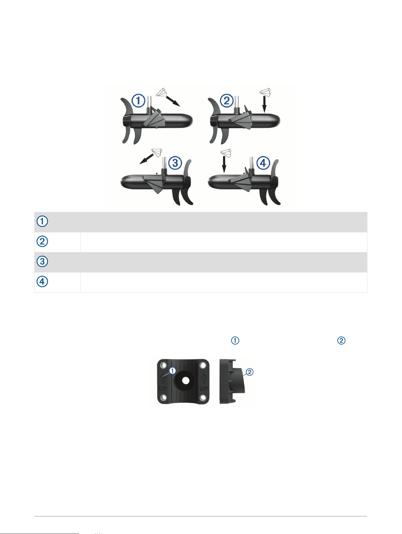
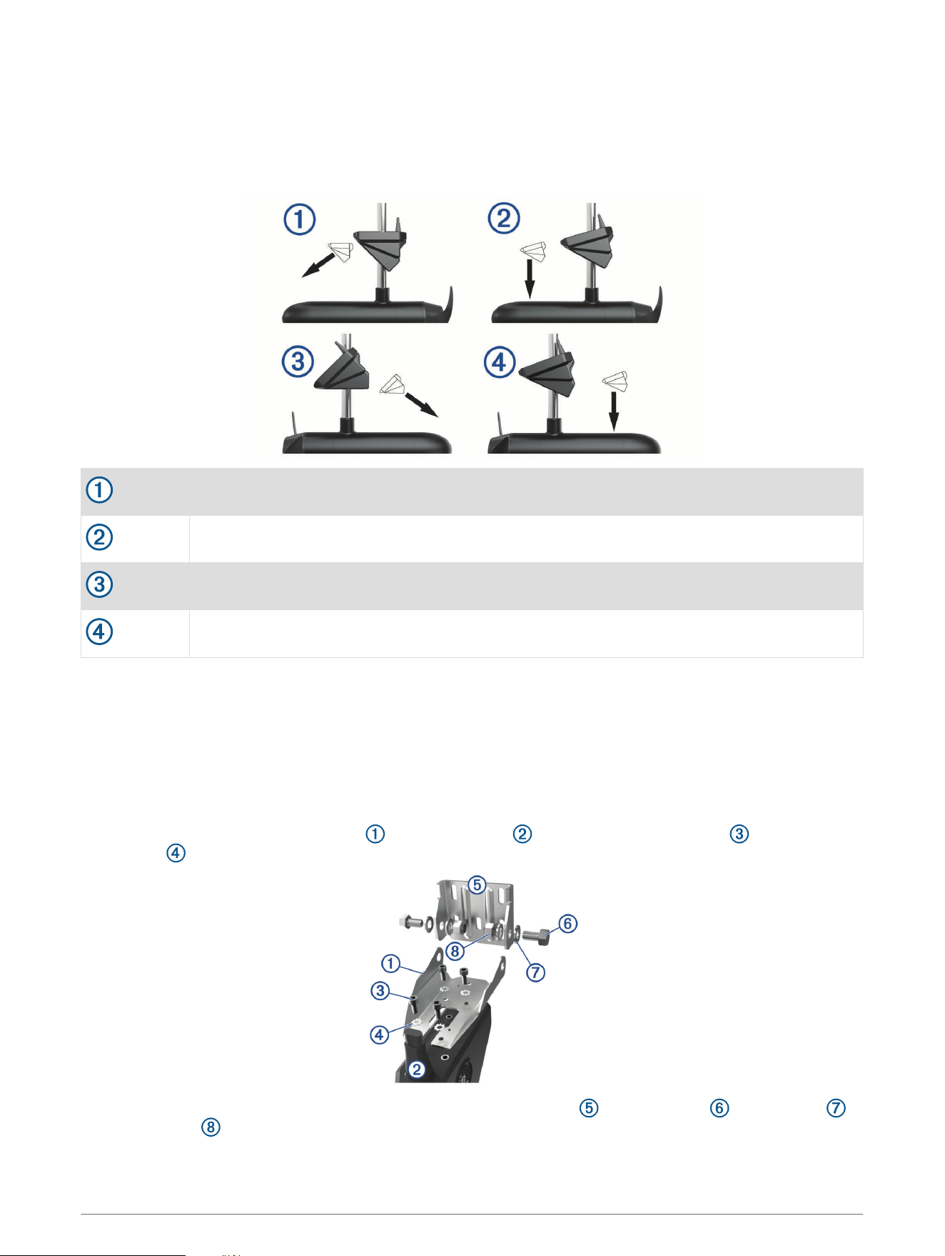
Trolling Motor Mount Orientation
The orientation depends on which side of the trolling motor you have mounted the transducer on, and your
desired field of view.
TIP: No tools are necessary to change the orientation from forward to down. Turn the mount one click to
change the orientation from forward to down.
Starboard side, forward view
Starboard side, downward view
Port side, forward view
Port side, downward view
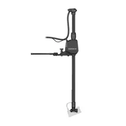
Installing the Transducer on a Trolling Motor Shaft
Trolling Motor Shaft Bracket Orientation
The trolling motor shaft bracket features an 8-degree cant to reduce the effects of the trolling motor barrel
interference with the transducer beam. You must orient the arrow and the narrow end of the angle to the
top when you attach the bracket to the trolling motor shaft.
5
Assembling the Trolling Motor Shaft Mount Hardware
With the trolling motor bracket oriented correctly (Trolling Motor Shaft Bracket Orientation, page 5), use the
included hex wrench to attach the transducer to the trolling shaft bracket with the shoulder screw ,
flat washer , and rubber washer .
NOTE: You must fully tighten the mount to the transducer. The recommended torque applied to the shoulder
screw is 2.5 lb-ft. (3.4 N-m).
Installing the Transducer on the Trolling Motor Shaft
NOTICE
You must secure the transducer cable to the shaft or other secure location during installation. Damage to the
transducer cable wire or the cable jacket can cause transducer failure.
You should mount the transducer as far from the motor as possible.
You should use the included rubber insert on a 25 mm (1 in.) trolling motor shaft.
1 Using the included hex wrench, insert the M6 screws and attach the shaft trolling bracket to the
transducer bracket around the trolling motor shaft.
2 Secure the transducer cable to the motor shaft or other secure location.
3 Route the transducer cable to the installation location of the sonar module while taking these precautions.
• You should not route the cable close to electrical wires or other sources of electrical interference.
• You must route the cable so it is not pinched when the trolling motor is deployed or stowed.
4 Position the transducer to your desired angle (Trolling Motor Shaft Orientation, page 7).
6
Trolling Motor Shaft Orientation
The angle of installation depends on the side of the trolling motor shaft you mount the bracket on, and your
desired field of view.
TIP: No tools are necessary to change the orientation from forward to down. Turn the mount one click to
change the orientation from forward to down.
Port side, forward view
Port side, downward view
Starboard side, forward view
Starboard side, downward view
Installing the Transducer on a Transom
Optional Spray Shield Accessory
If necessary, to reduce spray from the transducer, you can install an optional spray shield (010-12406-00). Go
to buy.garmin.com or contact your Garmin dealer for information.
Assembling the Transom-Mount Hardware
1 Attach the transducer mount bracket to the transducer using the mounting screws and lock
washers .
2 Attach the transducer mount bracket to the transom mount bracket using the bolts , flat washers ,
and lock nuts .
NOTE: The recommended torque applied to the bolts is 15 lb-ft. (20 N-m).
7
Installing the Transom-Mount Hardware
NOTICE
If you are mounting the bracket on fiberglass with screws, it is recommended to use a countersink bit to drill a
clearance counterbore through only the top gel-coat layer. This will help to avoid cracking in the gel-coat layer
when the screws are tightened.
1 Place the transducer mount so the top of the transducer is even with or up to 12.7 mm (
1
/
2
in.) above the
bottom edge of the transom.
2 Using the transom mount as a template, mark the location of the pilot holes.
3 Wrap a piece of tape around a 4 mm (
5
/
32
in.) bit at 19 mm (
7
/
10
in.) from the point of the bit, to avoid drilling
the pilot holes too deep.
4 If you are installing the bracket on fiberglass, place a piece of tape over the pilot-hole location to reduce
cracking of the gel coat.
5 Using the 4 mm (
5
/
32
in.) bit, drill the pilot holes approximately 19 mm (
3
/
4
in.) deep at the marked locations.
6 Apply marine sealant to the included 20 mm screws.
7 Using the four 20 mm screws , attach the transducer mount to the transom.
NOTICE
When mounting the transducer, be sure to secure all four corners of the mount with the included screws .
This is especially important on vessels that operate at high speeds. If only the top or bottom holes are used,
the bracket may bend or break when the vessel moves at high speeds, dislodging the transducer.
8 If you must route the cable through the transom, choose a pilot-hole location well above the waterline and
mark it.
9 If you marked a pilot hole in step 8, use a 32 mm (1
1
/
4
in.) hole saw to drill a pass-through hole completely
through the transom.
10 Route the transducer cable to the sonar module:
• If you are routing the cable using a pass-through hole, push it through the hole you drilled in step 9.
• If you are not routing the cable using a pass-through hole, route the cable up and over the top of the
transom .
You should avoid routing the cable close to electrical wires or other sources of electrical interference.
8

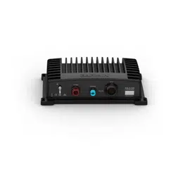
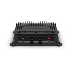
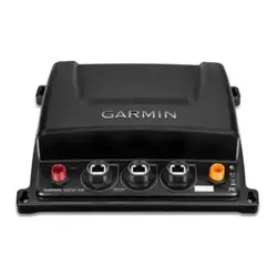
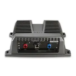
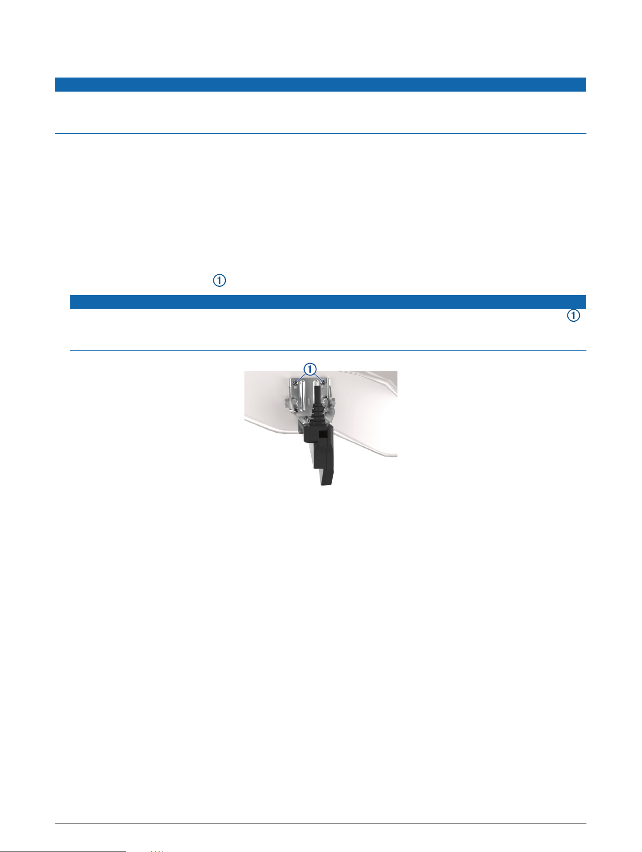
Mounting the GLS 10 Black Box Device
NOTICE
If you are mounting the device in fiberglass, when drilling the pilot holes, use a countersink bit to drill a
clearance counterbore through only the top gel-coat layer. This will help to avoid cracking in the gel-coat layer
when the screws are tightened.
NOTE: Screws are included with the device, but they may not be suitable for the mounting surface.
Before you mount the device, you must select a mounting location, and determine what screws and other
mounting hardware are needed for the surface.
1 Place the black box device in the mounting location, and mark the location of the pilot holes.
2 Drill a pilot hole for one corner of the device.
3 Loosely fasten the device to the mounting surface with one corner, and examine the other three pilot-hole
marks.
4 Mark new pilot-hole locations if necessary, and remove the device from the mounting surface.
5 Drill the remaining pilot holes.
6 Secure the device to the mounting location.
9
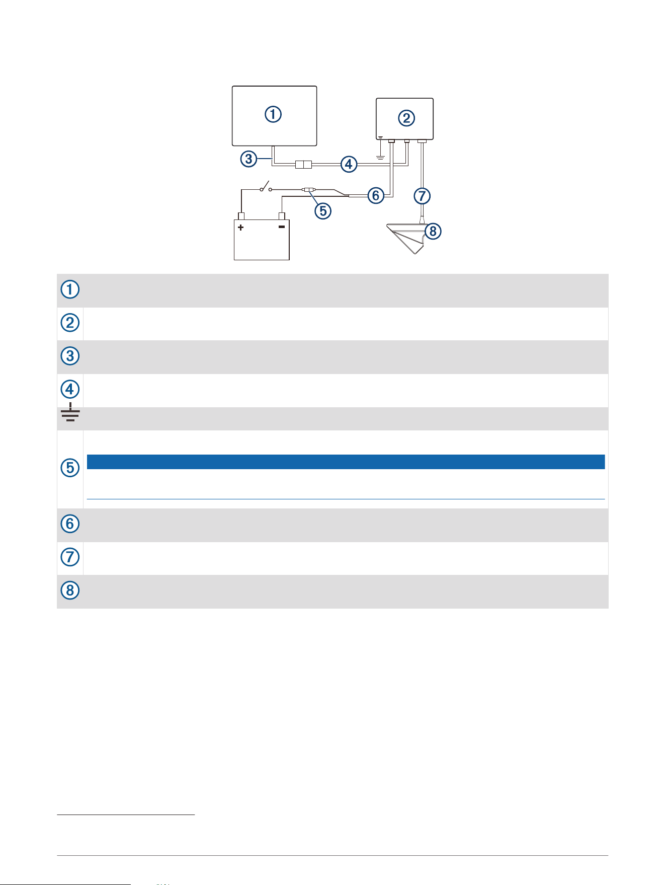
Installation Diagram
Compatible Garmin chartplotter
1
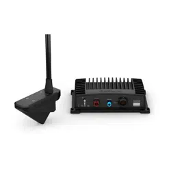
Panoptix LiveScope GLS 10 sonar module
Garmin Marine Network adapter cable (Garmin part number 010-12531-01)
Garmin Marine Network cable, small connector to NETWORK port
Water ground
7.5 A, fast-acting fuse
NOTICE
Do not remove the fuse. Removing the fuse may cause the device to malfunction and will void the
warranty.
Panoptix LiveScope GLS 10 power cable to POWER port
Transducer cable to XDCR port
Panoptix LiveScope LVS32 transducer
1
For chartplotter connections, refer to your chartplotter installation instructions.
10
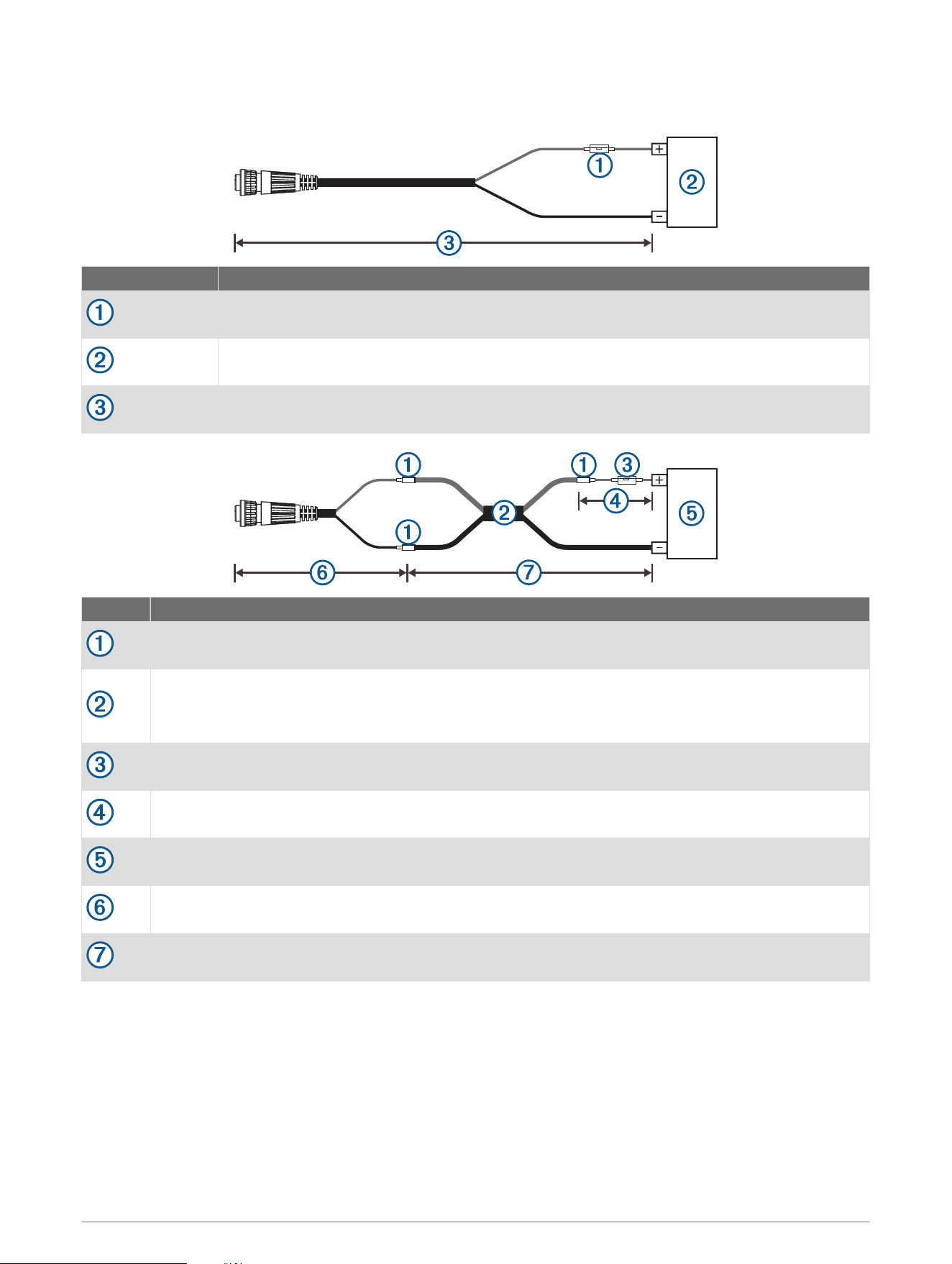
Power Cable Extensions
If necessary, you can extend the power cable using the appropriate wire gauge for the length of the extension.
Item Description
Fuse
Battery
9 ft. (2.7 m) no extension
Item Description
Splice
• 10 AWG (5.26 mm²) extension wire, up to 4.6 m (15 ft.)
• 8 AWG (8.36 mm²) extension wire, up to 7 m (23 ft.)
• 6 AWG (13.29 mm²) extension wire, up to 11 m (36 ft.)
Fuse
8 in. (20.3 cm)
Battery
8 in. (20.3 cm)
Maximum extension 36 ft. (11 m)
11

Blink Codes
After the sonar module is installed, it turns on when the chartplotter is turned on. The color status LED on the
sonar module indicates its operational status.
LED Color State Status
Green Blinking
The sonar module is connected to a chartplotter and is operating
properly. You should see sonar data on the chartplotter.
Red Blinking
The sonar module is turned on, but is not connected to a chartplotter,
or is waiting to connect to a chartplotter. If the sonar module is
connected to the chartplotter and this code persists, check the wiring
connections.
Orange Blinking A software update is in progress.
Red/Green Blinking Reserved
Red
Two blinks followed by a
3-second pause
Other sonar failure.
Red
Three blinks followed by a
3-second pause
The transducer is not detected by the sonar module. If this code
persists, check the wiring connections.
Red
Five blinks followed by a
3-second pause
The sonar module input voltage exceeds the maximum input voltage.
Transducer Settings and Operation
For transducer settings and operation information, see your chartplotter owner's manual.
Calibrating the Compass
Before you can calibrate the compass, the transducer must be installed on the shaft far enough away from the
trolling motor to avoid magnetic interference, and deployed in the water. Calibration must be of sufficient
quality to enable the internal compass.
NOTE: To use the compass, you must mount the transducer on the transom or the trolling motor shaft. The
compass may not work when you mount the transducer on the motor.
NOTE: For best results, you should use a heading sensor such as the SteadyCast
™
heading sensor. The heading
sensor shows the direction the transducer is pointing relative to the boat.
You can begin turning your boat before calibrating, but you must fully rotate your boat 1.5 times during
calibration.
1 From an applicable sonar view, select MENU > Sonar Setup > Installation.
2 If necessary, select Use AHRS to turn on the AHRS sensor.
3 Select Calibrate Compass.
4 Follow the on-screen instructions.
12

Specifications
Panoptix LiveScope LVS32 Specifications
Dimensions (L x H x W) 136.4 x 96.5 x 44.5 mm (5.37 x 3.8 x 1.75 in.)
Weight (transducer only) 850 g (1.87 lb.)
Frequencies From 530 to 1.1 MHz
Operating temperature From 0 to 40°C (from 32 to 104°F)
Storage temperature From -40 to 85°C (from -40 to 185°F)
Maximum depth/distance
1
61 m (200 ft.)
Field of view
Front to back: 135 degrees
Side-to-side: 20 degrees
Panoptix LiveScope GLS 10 Sonar Module Specifications
Dimensions (W x H x D) 245 x 149 x 65 mm (9.7 x 5.9 x 2.6 in.)
Weight 1.96 kg (4.33 lbs.)
Operating temperature From -15 to 70°C (from 5 to 158°F)
Storage temperature From -40 to 85°C (from -40 to 185°F)
Power input From 10 to 32 Vdc
Power usage 21 W typical, 24 mW min., 58 W max.
Compass-safe distance 178 mm (7 in.)
Data output Garmin Marine Network
Open-Source Software License
To view the open-source software license(s) used in this product, go to developer.garmin.com/open-source
/linux/.
Cleaning the Transducer
Aquatic fouling accumulates quickly and can reduce your device's performance.
1 Remove the fouling with a soft cloth and mild detergent.
2 Wipe the device dry.
© 2018 Garmin Ltd. or its subsidiaries
Garmin
®
, ActiveCaptain
®
, and the Garmin logo are trademarks of Garmin Ltd. or its subsidiaries, registered in the USA and other countries. LiveScope
™
and Panoptix
™
are
trademarks of Garmin Ltd. or its subsidiaries. These trademarks may not be used without the express permission of Garmin.
Android
™
is a trademark of Google Inc. Apple
®
and Mac
®
are trademarks of Apple Inc., registered in the U.S. and other countries. Wi‑Fi
®
is a registered trademark of Wi-Fi
Alliance Corporation. Windows
®
is a registered trademark of Microsoft Corporation in the United States and other countries. Other trademarks and trade names are those
of their respective owners.
1
Dependent upon water salinity, bottom type, and other water conditions.
13

© 2018 Garmin Ltd. or its subsidiaries
support.garmin.com