SPY
™
POLE
Owner's
Manual

Table of Contents
Important Safety Information............3
Turning the Spy Pole On or Off......... 4
Adjusting the Depth of the Spy
Pole..................................................5
Pairing a Spy Foot Control................ 6
Pairing a Spy Gesture Remote.......... 7
Pairing a Spy Heading Sensor...........8
Pairing With a Garmin
®
Trolling
Motor............................................... 9
Connecting to a Garmin
®
Chartplotter.................................... 10
Updating the Spy Pole Software......11
Spy Heading Sensor Calibration......12
Performing Menu-Based Calibration...12
Adjusting the Fine
Heading Alignment...................... 12
Controlling the Device with the Spy
Foot Control................................... 13
Controlling the Device with the Spy
Gesture Remote..............................14
Controlling the Device with a
Chartplotter.................................... 15
Programming the Spy Foot
Control Buttons.............................. 16
Programming the Spy Gesture
Remote Buttons..............................17
Replacing the Battery in the Gesture
Remote...........................................18
Replacing the Batteries in the Spy
Foot Control................................... 19
Using Advanced Spy
Pole Features................................. 20
Stowing and Deploying
Considerations............................... 21
Stowing or Deploying the Spy Pole on a
Trolling Motor................................21
Stowing and Deploying the Spy Pole on a
Gunnel Mount................................21
Setting the Spy Pole Automatic
Park Settings.................................21
Specifications................................ 22
Spy Pole Specifications................... 22
Spy Gesture Remote Specifications....22
Spy Foot Control Specifications........ 22
Spy Heading Sensor Specifications.... 22
Status LEDs.................................... 24
Button Combinations...................... 25

Important Safety Information
WARNING
See the Important Safety and Product Information guide in the product box for product warnings and other
important information.
Important Safety Information Spy™ Pole
Owner's Manual
3

Turning the Spy Pole On or Off
The Spy pole turns on automatically after power is supplied, but you can also turn the device on and off
manually. You can enable or disable the automatic power on features from a connected Garmin
®
chartplotter.
1 Ensure the power cable is connected to the Spy pole and to the power supply, and the locking ring is fully
tightened.
The red LED turns on and then, after several seconds, turns green to indicate that the Spy pole is on and
ready.
2 Press on the Spy pole until the LED turns off.
The Spy pole is off.
3 To turn the Spy pole on again, press and hold until the LED turns back on.
4 Spy™ Pole
Owner's Manual
Turning the Spy Pole On or Off

Adjusting the Depth of the Spy Pole
You can change the depth of the Spy pole after it has been installed. The device can slide up or down,
depending on where you have installed the depth ring along the pole.
NOTICE
If you installed the Spy pole on a trolling motor, you must set the depth-indicator ring at a point that prevents
the spy pole from being lowered deep enough to contact the propeller of the trolling motor. If the trolling motor
propeller contacts the Spy pole, it can damage the Spy pole, any attachments on the pole, and the propeller.
1 Loosen the depth adjustment collar.
2 Slide the pole up or down through the Spy pole housing to the preferred depth.
3 Tighten the depth adjustment collar to set the preferred depth.
Adjusting the Depth of the Spy Pole
Spy™ Pole
Owner's Manual
5

Pairing a Spy Foot Control
The Spy pole can pair with one foot control at a time. The Spy pole is already paired with the included foot
control, but you can also initiate pairing manually if needed.
1 Turn on the Spy pole.
2 Press on the Spy pole three times.
The LED turns solid blue, indicating that the device is pairing.
3 On the foot control, press the top two programmable buttons simultaneously three times.
The LED on the foot control flashes blue, indicating that the device is pairing.
4 Wait for the two devices to pair.
The LED on the Spy pole turns green again and the LED on the foot control flashes green after the devices
are paired successfully.
6 Spy™ Pole
Owner's Manual
Pairing a Spy Foot Control

Pairing a Spy Gesture Remote
The Spy pole can pair with up to five gesture remotes. The Spy pole is already paired with the included remote,
but you can also initiate pairing manually if needed.
1 Turn on the Spy pole.
2 Press on the Spy pole three times.
The LED turns solid blue, indicating that the device is pairing.
3 On the remote, press the left and right buttons simultaneously three times.
The LED on the remote flashes blue, indicating that the device is pairing.
4 Wait for the remote to pair with the Spy pole.
The LED on the Spy pole turns green again and the LED on the remote flashes green after the devices are
paired successfully.
Pairing a Spy Gesture Remote
Spy™ Pole
Owner's Manual
7

Pairing a Spy Heading Sensor
A Spy pole can pair to one Spy heading sensor at a time. The Spy pole is already paired with the included sensor,
but you can also initiate pairing manually if needed. If you have multiple Spy poles, a single Spy heading sensor
can connect to up to 4 Spy poles.
If you already have a reliable NMEA 2000
®
heading sensor connected to a Garmin
®
chartplotter, you do not need
to install the Spy heading sensor. The advanced control modes for the Spy pole will work as intended with your
existing heading sensor.
1 Turn on the Spy pole.
2 Press on the Spy pole three times.
The LED turns solid blue, indicating that the device is pairing.
3 On the heading sensor, press the button three times.
The LED on the heading sensor turns solid blue, indicating that the device is pairing.
4 Wait for the heading sensor to pair with the Spy pole.
The LED on the Spy pole turns green again and the LED on the heading sensor flashes green after the
devices are paired successfully.
8 Spy™ Pole
Owner's Manual
Pairing a Spy Heading Sensor

Pairing With a Garmin
®
Trolling Motor
The Spy pole can pair with one Garmin Force
®
trolling motor at a time. A trolling motor can only pair to one Spy
pole at a time.
1 Turn on the Spy pole.
2 Press on the Spy pole three times.
The LED turns solid blue, indicating that the device is pairing.
3 On the trolling motor, press three times.
The pairing LED on the trolling motor turns blue, indicating that the device is pairing.
4 Wait for the trolling motor to pair with the Spy pole.
The LED on the Spy pole and trolling motor turn green again after the devices are paired successfully.
Pairing With a Garmin
®
Trolling Motor Spy™ Pole
Owner's Manual
9

Connecting to a Garmin
®
Chartplotter
The Spy pole can connect with one compatible Garmin chartplotter at a time. After connecting the Spy pole with
a chartplotter, you can control it using any other chartplotter connected to the same Garmin BlueNet
™
or Garmin
Marine Network.
Up to four Spy poles can connect to one Garmin Marine Network at any one time.
Go to www.garmin.com for a list of compatible chartplotters.
1 Turn on the Spy pole.
2 Press on the Spy pole three times.
The LED turns solid blue, indicating that the device is connecting.
3 On the chartplotter, select Home> Settings> Communications> Wireless Devices> Spy™ Pole Mount>
Start.
4 Wait for the chartplotter to connect to the Spy pole.
The LED on the Spy pole turns green again after the devices are connected successfully.
10 Spy™ Pole
Owner's Manual
Connecting to a Garmin
®
Chartplotter

Updating the Spy Pole Software
If the Spy pole is connected to a compatible chartplotter, it is updated automatically whenever you update the
software on the chartplotter. You can also manually update the Spy Pole using the ActiveCaptain
®
app.
1 Turn off the Spy pole.
2 Hold until the status LED turns yellow.
3 Connect your mobile device to the dedicated Wi‑Fi
®
network on the Spy pole.
The dedicated network name starts with "SPY" and contains a series of numbers unique to the device.
4 Open the ActiveCaptain app on your mobile device.
5 Disconnect the mobile device from the Spy pole network and connect it to the internet.
6 From the ActiveCaptain app, select My Marine Devices> Download.
NOTE: The option to download an update is shown only if a software update is available for your device.
The ActiveCaptain app downloads the update to your mobile device.
7 Turn on all Spy pole peripherals to ensure they are also updated.
8 Reconnect your mobile device to the Spy pole network.
The update is transferred to the Spy pole. This could take up to 30 minutes to complete.
The status LED on the Spy pole flashes purple to indicate that the software is updating.
If the transfer finishes but the status LED on the Spy pole does not start flashing, you should turn off the Spy
pole and turn it back on to complete the update.
Updating the Spy Pole Software
Spy™ Pole
Owner's Manual
11

Spy Heading Sensor Calibration
When you connect the Spy pole with a paired heading sensor to a compatible Garmin
®
chartplotter, the Spy
Pole Setup Wizard will prompt you for calibration during setup. Otherwise, you can perform menu-based
calibration through the Spy Pole toolbar on your chartplotter (Performing Menu-Based Calibration, page12).
Go to www.garmin.com for a list of compatible chartplotters.
NOTICE
After installation is complete, you must calibrate the Spy heading sensor, as it does not provide heading data
until it is calibrated.
Performing Menu-Based Calibration
The heading sensor comes paired to your Spy pole. Before you can perform menu-based calibration, the Spy
pole must be connected to a compatible Garmin
®
chartplotter (Connecting to a Garmin
®
Chartplotter, page10).
You can calibrate your heading sensor from the menu of a compatible Garmin chartplotter.
1 From the home screen of your chartplotter, select Toolbars> Spy™ Pole.
2 Select a location for the Spy pole toolbar.
3 Open the Spy pole toolbar.
4 Select Menu> Installation> Calibrate> Spy™ Heading Sensor.
The calibration wizard opens.
5 Select Begin.
6 Follow the on-screen instructions until the compass calibration is complete, taking care to keep the boat as
steady and level as possible.
The boat should not list during calibration.
If possible, you can turn the vessel in place by engaging two engines in opposite directions.
If the heading performance is unacceptable after calibration, you may need to relocate the sensor and
calibrate the compass again. Refer to the Spy
pole installation instructions for further details.
7 Select Auto Heading Alignment.
Auto Heading Alignment is available only if there is a GPS source present on the Garmin BlueNet
™
network
or Garmin Marine Network. If a GPS source is not connected, you must perform the Fine Heading Alignment
instead (Adjusting the Fine Heading Alignment, page12).
8 Select Begin.
9 Follow the on-screen instructions until the alignment is complete.
Adjusting the Fine Heading Alignment
If you do not have a GPS source present on the Garmin BlueNet
™
network or Garmin
®
Marine Network, the Auto
Heading Alignment option is not available as part of menu-based calibration. You must adjust the Fine Heading
Alignment instead.
You can adjust the Fine Heading Alignment in conjunction with Auto Heading Alignment to fine-tune the heading
output (optional).
1 Start the Spy heading sensor calibration, and skip directly to Fine Heading Alignment.
2 Using a landmark or a known good compass, determine the heading of your boat.
3 Adjust the heading until it matches your measurement.
4 Select Done.
12
Spy™ Pole
Owner's Manual
Spy Heading Sensor Calibration
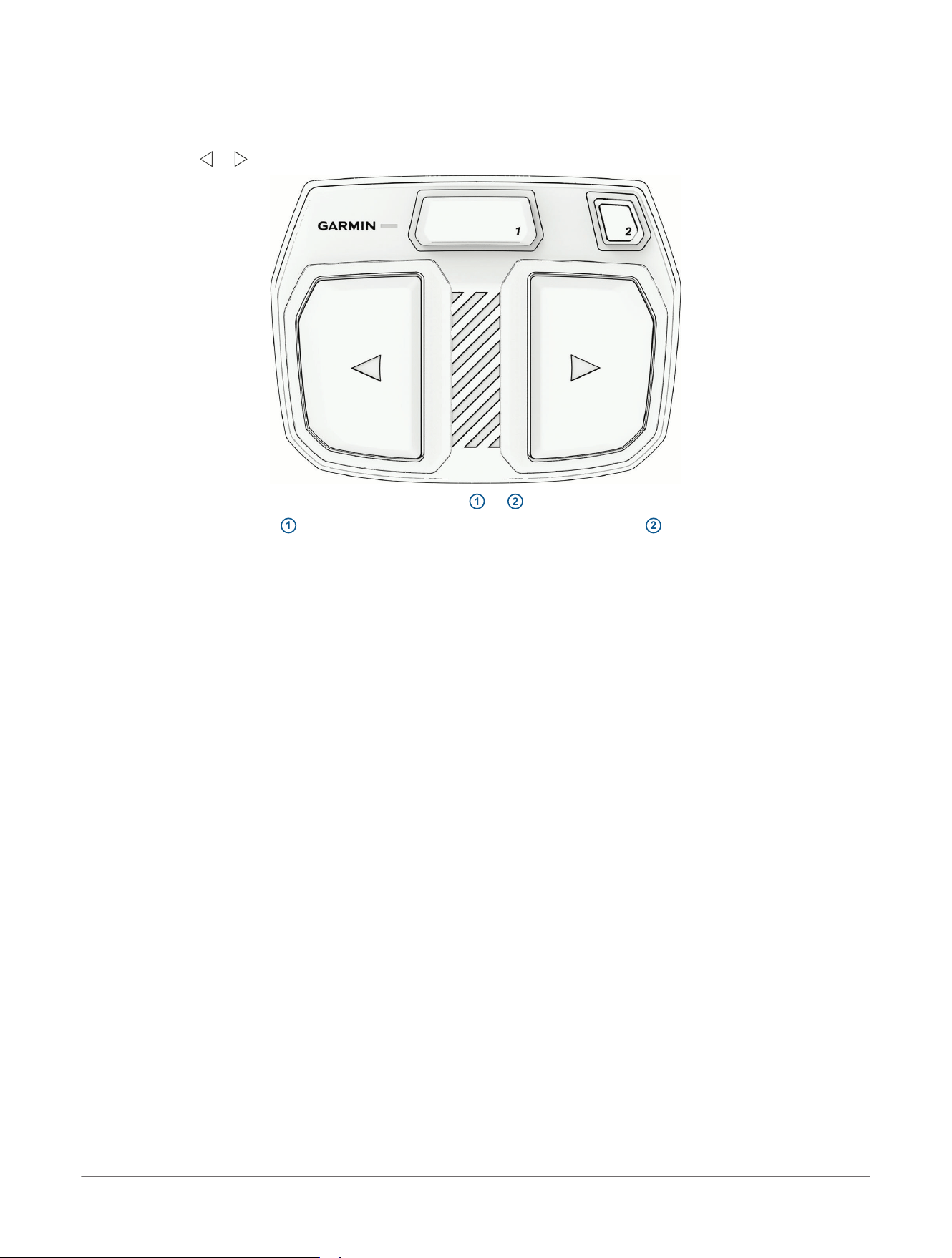
Controlling the Device with the Spy Foot Control
You can use the foot control to maneuver the Spy pole. You can also use the programmable buttons to engage
other features of the device.
1 Use the large or control buttons to turn the Spy pole that direction.
2 When needed, press the top programmable buttons
1
or
2
to activate other features of the Spy pole.
NOTE: By default, button
1
performs the "Toggle Gesture" action and button
2
performs the "Engage
SpyScan
™
" action.
NOTE: You can change the actions performed by these buttons after you have connected the Spy pole to a
compatible chartplotter (Programming the Spy Foot Control Buttons, page16).
Controlling the Device with the Spy Foot
Control
Spy™ Pole
Owner's Manual
13
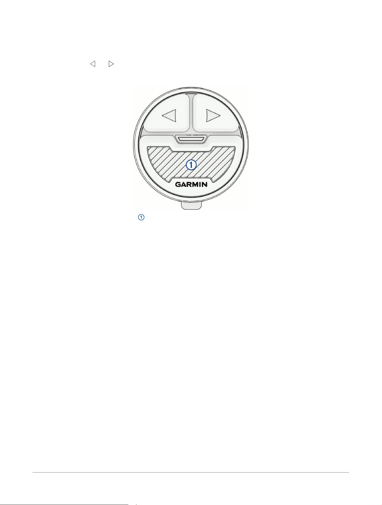
Controlling the Device with the Spy Gesture Remote
You can use the gesture remote to maneuver the Spy pole. You can also use the programmable buttons to
engage other features of the device.
1 By default, press and to turn the Spy pole.
You can program these buttons to activate other features of the Spy pole instead after you have connected
the Spy pole to a compatible chartplotter (Programming the Spy Gesture Remote Buttons, page17).
2 Press and hold the bottom button
1
to enable gesture control of the Spy pole.
You can program the gesture control type (pan or tilt) after you have connected the Spy pole to a compatible
chartplotter (Programming the Spy Gesture Remote Buttons, page17).
14
Spy™ Pole
Owner's Manual
Controlling the Device with the Spy
Gesture Remote

Controlling the Device with a Chartplotter
You can use a compatible Garmin
®
chartplotter to maneuver the Spy pole. You can also use the chartplotter to
engage other features of the device.
For more details, see the latest version of your chartplotter owner's manual.
1 Open the Spy pole toolbar (Performing Menu-Based Calibration, page12).
2 Select and to turn the Spy pole.
3 Use the other buttons on the interface to activate and control other features of the Spy pole.
Controlling the Device with a Chartplotter Spy™ Pole
Owner's Manual
15

Programming the Spy Foot Control Buttons
Before you can program the buttons on the Spy foot control, you must connect the Spy pole to a compatible
chartplotter (Connecting to a Garmin
®
Chartplotter, page10).
The foot control includes 2 buttons that you can program to perform several different functions.
1 On the chartplotter, open the Spy pole toolbar and select > Foot Control.
2 Select a function for each of the two control buttons.
16 Spy™ Pole
Owner's Manual
Programming the Spy Foot Control
Buttons

Programming the Spy Gesture Remote Buttons
Before you can program the buttons on the Spy gesture remote, you must connect the Spy pole to a compatible
chartplotter (Connecting to a Garmin
®
Chartplotter, page10).
You can program the and buttons on the gesture remote to perform several different functions.
1 On the chartplotter, open the Spy pole toolbar and select > Gesture Remote.
2 Select a function for the and buttons.
3 Select the gesture control type (Swing To Steer or Twist To Steer) for the gesture control button.
Programming the Spy Gesture Remote
Buttons
Spy™ Pole
Owner's Manual
17

Replacing the Battery in the Gesture Remote
WARNING
See the Important Safety and Product Information guide in the product box for product warnings and other
important information.
A battery is already installed in the Spy gesture remote, and you can replace it when necessary.
1 Remove the gesture remote from any remote mount.
2 Using a #1 Phillips screwdriver, unscrew the three screws on the back of the remote.
3 Remove the back of the remote to access the battery terminal.
4 Remove the dead battery and dispose of it safely.
You may need to use a flat prying tool to remove the battery from the housing.
5 Place the new battery in the back housing, with the positive (+) side facing down.
6 Place the back of the housing onto the remote and secure it using the three screws you removed previously.
NOTICE
You must tighten the screws enough to fasten the back housing onto the remote securely. Improperly
tightening the screws to secure the back housing can lead to water ingress and damage the remote.
18 Spy™ Pole
Owner's Manual
Replacing the Battery in the Gesture
Remote

Replacing the Batteries in the Spy Foot Control
1 Pull the foot control toward you to release it from the mount plate.
2 Open the battery door on the underside of the foot control.
3 Replace the batteries, making sure to observe the polarity when installing the new batteries.
4 Close the battery door.
5 Set the foot control on the mount plate and push it away from you until it clicks into place.
Replacing the Batteries in the Spy Foot
Control
Spy™ Pole
Owner's Manual
19

Using Advanced Spy Pole Features
Before you can take advantage of all the features of your Spy pole, you must connect it to a compatible Garmin
®
chartplotter and perform required configuration and calibration procedures.
1 Go to garmin.com/manuals.
2 Enter the name of your chartplotter and select the right model.
3 Select the Owner's Manual on the manuals page.
4
Refer to the Spy pole control chapter for instructions to set up and use features such as SpyLink
™
synchronization, SpyScan
™
search mode, and SpyLock
™
locking.
NOTE: The advanced features available on the chartplotter depend on the availability of other required
hardware such as a Garmin trolling motor and a Spy heading sensor.
20 Spy™ Pole
Owner's Manual
Using Advanced Spy Pole Features

Stowing and Deploying Considerations
You can stow or deploy the Spy Pole in different ways to best suit how the device is mounted on your vessel.
NOTICE
You should stow the Spy Pole whenever your vessel is traveling at speeds greater than trolling speeds. Traveling
faster than a trolling speed with the Spy deployed may damage the Spy Pole or any devices mounted to the Spy
Pole.
If the Spy Pole is mounted on a trolling motor, you should refer to the trolling motor stowing instructions
(Stowing or Deploying the Spy Pole on a Trolling Motor, page21).
If the Spy Pole is mounted on the gunnel mount (not included), you should refer to the gunnel mount stowing
instructions (Stowing and Deploying the Spy Pole on a Gunnel Mount, page21).
You can control how the Spy Pole reacts when you stow or deploy it by adjusting the automatic park settings
from your chartplotter (Setting the Spy Pole Automatic Park Settings, page21).
Stowing or Deploying the Spy Pole on a Trolling Motor
If the Spy pole is mounted on a trolling motor, the Spy pole is stowed and deployed automatically when you
stow and deploy the trolling motor.
1 To stow the Spy pole, use the pull-cable on your trolling motor to pull the motor out of the water and into the
stowed position.
The Spy pole moves out of the water with the trolling motor and rests in the stowed position.
2 To deploy the Spy pole, pull the pull-cable on the trolling motor back until it stops to release the latch, and
hold it tight.
3 Lift the motor and Spy pole assembly up and forward using the pull-cable, then lower it slowly into the
deployed position.
4 If necessary, push down on the mount arm to lock the assembly in the deployed position.
The Spy pole and trolling motor are deployed in the water and ready to use.
Stowing and Deploying the Spy Pole on a Gunnel Mount
If the Spy pole is installed on a gunnel mount, you can stow or deploy the Spy pole by manually moving it on the
mount.
1 To stow the Spy pole, unlatch the quick-release lever on the gunnel mount's horizontal tube.
2 Rotate the Spy pole until it is parallel to the water.
3 Relatch the quick-release lever to hold the Spy pole out of the water.
4 Pull one of the silver security pins from the tube-connector bracket and push it through the concentric holes
in the bracket and horizontal tube.
The Spy pole is securely stowed out of the water.
5 To deploy the Spy Pole, remove the silver security pin and return it to the storage hole on the tube-connector
bracket.
6 Hold onto the Spy Pole while you unlatch the quick-release lever.
7 Gently lower the Spy Pole into the water.
8 Relatch the quick-release lever.
The Spy Pole is deployed and ready to use.
Setting the Spy Pole Automatic Park Settings
With the automatic park feature, you can set the Spy pole to automatically rotate into a parked position when it
is stowed. When deployed, the Spy pole automatically rotates into the active position. This feature is disabled by
default, but you can enable it through your connected chartplotter settings.
CAUTION
Take care when holding onto the Spy pole shaft while stowing the device when the automatic park features are
enabled. The device can rotate in your hands and can potentially cause minor injuries or damage the device.
1 On a connected chartplotter, open the Spy pole control bar.
2 Select > Installation> Transducer Auto Park.
3 Adjust the automatic park settings for your Spy pole as needed.
Stowing and Deploying Considerations
Spy™ Pole
Owner's Manual
21

Specifications
Spy Pole Specifications
Weight (motor, mount, and cables) 42in. model: 4.1kg (9 lbs)
49in. model: 4.24kg (9.35 lbs)
Operating temperature From -5° to 55°C (23° to 131°F)
Storage temperature From -40° to 85°C (-40° to 185°F)
Power cable length 2 m (6.6 ft)
Input voltage From 10 to 45Vdc
Input amperage 1.5 A RMS
7 A Peak
Fuse information 8 A (included)
Power usage Off: <10mW
Typical: 18 W
Max: 70W
Radio frequency 2400 - 2483.5 MHz @ <20 dBm nominal
Water rating
IEC 60529 IPX7
1
Compass safe distance 48.3cm (19 in.)
Spy Gesture Remote Specifications
Dimensions (W×H×D) 32 mm diameter x 13 mm thick (1.25 in. diameter x 0.5 in thick)
Weight (with included battery) 14g (0.5 oz)
Operating temperature From -15° to 55°C (5° to 131°F)
Storage temperature From -40° to 85°C (-40° to 185°F)
Battery type 1 CR2032 (included)
Battery life 1 full season, typical use
Radio frequency 2400 - 2483.5 MHz @ <20 dBm nominal
Water rating
IEC 60529 IPX7
1
Compass-safe distance 2.5 cm (1 in.)
Spy Foot Control Specifications
Dimensions (W×H×D) 198 x 147 x 46mm (7.8 x 5.8 x 1.8in.)
Weight (without batteries) 0.48kg (1.06 lbs)
Operating temperature From -15° to 55°C (5° to 131°F)
Storage temperature From -40° to 85°C (-40° to 185°F)
Battery type 2 AA (not included)
Battery life 1 full season, typical use
Radio frequency 2400 - 2483.5 MHz @ <20 dBm nominal
Water rating
IEC 60529 IPX7
1
Compass-safe distance 12.7 cm (5 in.)
Spy Heading Sensor Specifications
Dimensions (W×H×D) 90 x 50 x 25mm (3.5 x 2 x 1in.)
Weight 122 g (4.3 oz)
Operating temperature From -15° to 70°C (5° to 158°F)
Storage temperature From -40° to 85°C (-40° to 185°F)
1
The device withstands incidental exposure to water of up to 1m for up to 30min. For more information, go to www.garmin.com/waterrating.
22 Spy™ Pole
Owner's Manual
Specifications

Input voltage From 10 to 45 Vdc
Input amperage
0.1 A max
Fuse information 1 A (included)
Power Usage Off: <10 mW
Typical: 0.1 W
Max: 5 W
Radio frequency 2400 - 2483.5 MHz @ <20 dBm nominal
Water rating
IEC 60529 IPX7
1
Compass-safe distance 2.5cm (1 in.)
1
The device withstands incidental exposure to water of up to 1m for up to 30min. For more information, go to www.garmin.com/waterrating.
Specifications Spy™ Pole
Owner's Manual
23

Status LEDs
The Spy pole and its accessories each have an LED light that changes color to convey different meanings.
Spy Pole
Event LED Comment
Device Startup Solid red Boot in progress
Solid green System booted and ready
Pairing Solid blue Pairing mode enabled
Solid green Pairing successful
Device Update Flashing purple Update in progress
Device Fault Flashing red Servo fault detected (this light will remain until reboot, even if the fault is cleared)
System Recovery Solid yellow Device in recovery mode
Spy Gesture Remote
Event LED Comment
Device Startup Flashing green Battery normal
Flashing yellow Battery low
Flashing red Battery critical
Key Press Flashing green Connected
Flashing red Not connected
Pairing Flashing blue Pairing mode enabled
Flashing green Pairing successful
Clear Pairings Flashing red twice
Device Update Flashing purple Update in progress
Spy Foot Control
Event LED Comment
Device Startup Flashing green Battery normal
Flashing yellow Battery low
Flashing red Battery critical
Key Press Flashing green Connected
Flashing red Not connected
Pairing Flashing blue Pairing mode enabled
Flashing green Pairing successful
Clear Pairings Flashing red twice
Device Update Flashing purple Update in progress
Spy Heading Sensor
Event LED Comment
Key Press Flashing green Connected
Flashing red Not connected
Pairing Solid blue Pairing mode enabled
Flashing green Pairing successful
Clear Pairings and Calibration Flashing red twice
Device Update Flashing purple Update in progress
Iron Calibration Solid purple Calibration mode
Flashing green Calibration successful
Flashing red Calibration failed
24 Spy™ Pole
Owner's Manual
Status LEDs

Button Combinations
Different button combinations control different features on the Spy pole and its accessories.
Spy Pole
Feature Description
Power Button
Turn-Off
Press and hold for 3 seconds to turn the device off.
Pairing
Press 3 times in a row to put the Spy Pole into pairing mode.
Software Update
Press and hold while the Spy Pole is turned off until the status LED turns yellow. This puts the
device in update mode.
Clear Pairings Within 2 minutes of booting up the device, press the gesture button 12 times in a row to manually
prompt the device to clear all saved pairings, including all stored BLE pairings. The LED flashes red
twice.
Spy Gesture Remote
Feature Description
Pairing
Press the and buttons simultaneously 3 times in a row to put the gesture remote into pairing
mode.
Reset
Press and hold the and buttons simultaneously until the LED flashes (at least 8 seconds) to reset
the device.
Clear Pairings Within 2 minutes of booting up the device, press the gesture button 12 times in a row to manually
prompt the device to clear all saved pairings.
Spy Foot Control
Feature Description
Pairing
Press the
1
and
2
buttons simultaneously 3 times in a row to put the foot control into pairing mode.
Clear Pairings
Within 2 minutes of booting up the device, press 12 times in a row to manually prompt the device to
clear all saved pairings.
Spy Heading Sensor
Feature Description
Pairing Press the button 3 times in a row to put the heading sensor into pairing mode.
Reboot Press and hold the button for 3 seconds to reboot the device.
Clear Pairings and
Calibration
Within 2 minutes of booting up the device, press the button 12 times in a row to manually prompt
the device to clear all saved pairings and iron calibration.
Button Combinations Spy™ Pole
Owner's Manual
25

support.garmin.com
© 2026 Garmin Ltd. or its subsidiaries
Garmin
®
and the Garmin logo are trademarks of Garmin Ltd. or its subsidiaries, registered in the USA and other countries.
Force
®
, LiveScope
™
, and Spy
™
are trademarks of Garmin Ltd. or its subsidiaries. These trademarks may not be used without the express permission of Garmin.
NMEA
®
, NMEA 2000
®
, and the NMEA 2000 logo are registered trademarks of the National Marine Electronics Association.
March 2026 GUID-5E9D5954-EED9-410E-9E9E-D57EBC1DBAD3 v1