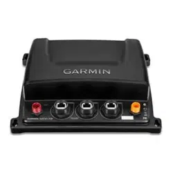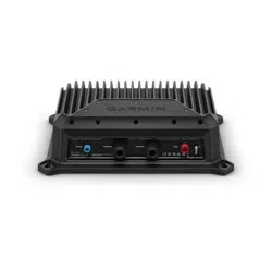
GSD
™
28 SONAR MODULE
INSTALLATION INSTRUCTIONS
Important Safety Information
WARNING
See the Important Safety and Product Information guide in the product box for product warnings and other
important information.
Failure to follow these warnings, cautions, and notices could result in personal injury, damage to the vessel or
device, or poor product performance.
You are responsible for the safe and prudent operation of your vessel. Sonar is a tool that enhances your
awareness of the water beneath your boat. It does not relieve you of the responsibility of observing the water
around your boat as you navigate.
CAUTION
To avoid possible personal injury, always wear safety goggles, ear protection, and a dust mask when drilling,
cutting, or sanding.
To avoid possible personal injury or damage to the device and vessel, disconnect the vessel's power supply
before beginning to install the device.
To avoid possible personal injury or damage to the device or vessel, before applying power to the device, make
sure that it has been properly grounded, following the instructions in the guide.
To avoid possible personal injury or damage to this device and vessel, only install this device when the vessel is
on land, or when properly secured and docked in calm water conditions.
For the best possible performance and to avoid potential injury, damage to the device, or damage to your vessel,
installation by a qualified marine installer is recommended.
NOTICE
When drilling or cutting, always check what is on the opposite side of the surface to avoid damaging the vessel.
Read all installation instructions before proceeding with the installation. If you experience difficulty during the
installation, contact Garmin Support.
Transducers
A transducer is required to send and receive a sonar signal from the sonar module. Proper transducer selection
and installation are critical to the operation of the device. Because mounting locations vary, see your local
Garmin dealer or contact Garmin Support for more information. Go to garmin.com/transducers to select a
transducer.
Installation Preparation
Because every boat is different, you must carefully plan the GSD 28 sonar module installation.
1 Select a mounting location.
2 Mount the sonar module.
3 Connect the sonar module to the transducer.
4 Connect the sonar module to power.
5 Connect the sonar module to the network.
GUID-50800D0A-1ECA-4747-9356-D7ECA366DC2B
v5
October 2024

Tools Needed
• Drill
• 5mm (
13
/
64
in.) drill bit for the mounting surface
• #2 Phillips screwdriver
• 3mm flat screwdriver
• Dielectric grease
• Wire cutter
• Wire stripper
• 1in. (24mm) wrench
• Cable ties (optional)
• Cable grommets (optional)
• Marine sealant (optional)
Replacing a GSD 26 Sonar Module
If you are upgrading from a GSD 26 sonar module, observe these considerations.
• The GSD 28 device is horizontally smaller than the GSD 26 device. If possible, you should reuse two of the
mounting holes on the right or left side of the mounting surface and drill two new holes for the opposite side.
Both models use the same size mounting screws.
• If your network includes a Garmin BlueNet chartplotter, we recommend connecting the GSD 28 sonar module
to your Garmin BlueNet chartplotter using a Garmin BlueNet cable, to ensure access to any future GSD 28
device software updates that may require Garmin BlueNet connectivity.
• You can use the included female-to-female Garmin BlueNet to Garmin Marine Network adapter to connect the
Garmin Marine Network cable from your previous GSD 26 installation to the GSD 28 device, without having
to route a new Garmin BlueNet cable to your chartplotter or port expander. We recommend this connection
method only for vessels without a Garmin BlueNet chartplotter.
Mounting the Sonar Module
Mounting Location Considerations
• You must mount the sonar module in a location where it cannot be submerged.
• You must mount the sonar module in a location with adequate ventilation where it will not be exposed to
extreme temperatures.
• You should mount the sonar module so that the LEDs are visible and the power and network cables can be
easily connected.
• You should mount the sonar module in a location within reach of your transducer cable. If required,
transducer extension cables are available through your Garmin dealer.
2
Mounting the Device
NOTICE
If you are mounting the device in fiberglass, when drilling the pilot holes, use a countersink bit to drill a
clearance counterbore through only the top gel-coat layer. This will help to avoid cracking in the gel-coat layer
when the screws are tightened.
NOTE: Screws are included with the device, but they may not be suitable for the mounting surface.
Before you mount the device, you must select a mounting location and determine what screws or other
mounting hardware are needed for the surface.
1 Trim the template and make sure it fits in the location where you want to mount the device.
2 Secure the template to the selected location.
3 Mark pilot holes for the four corner of the device, and remove the template.
4 Using a 5mm (
13
/
64
in.) drill bit, drill one of the pilot holes and lightly secure the device using one of the
screws or selected mounting hardware.
5 Verify the positions of the other pilot hole marks and adjust them as necessary.
6 Drill the remaining pilot holes.
7 Secure the device to the mounting location using the remaining screws or selected mounting hardware.
Sonar Module Connections
NOTICE
Do not force a cable into its port. Forcing the cable can damage the pins. If the cable is properly aligned, the
cable should connect easily.
Before you connect the sonar module to the transducer, network, and power, you must mount the sonar module
(Mounting the Sonar Module, page2).
Cable Routing Grommets
When routing cables through your boat, it may be necessary to drill holes to route the cables. Cable routing
grommets can be used to cover cable installation holes. The grommets do not create a waterproof seal. If
necessary, apply a marine sealant after installation to weatherproof around the grommet and the cable. You can
purchase grommets from your Garmin dealer or directly from Garmin at garmin.com.
Connecting the Device to a Transducer
WARNING
To avoid the risk of serious injury, make sure the device is not connected to power before removing the terminal
block lid.
NOTICE
The cord grips on the GSD 28 come with plugs installed. To ensure water cannot enter the transducer wiring
block area and damage the device, do not remove the plug from an unused cord grip, and tighten all locking
rings.
The terminal blocks are not removable.
3

Preparing the Cables to Connect to the Sonar Module
Before you can begin the installation, you must check your transducer compatibility.
NOTE: The device does not support water speed wheels.
1 Remove the terminal block lid from the sonar module, using a #2 Phillips screwdriver.
2 Loosen one of the cord grips, and remove the rubber plug.
If necessary, push the plug all the way through, and retrieve it from inside the terminal block area.
NOTE: When connecting two single-element transducers, you should use the transducer cord grip on the left
for a low-frequency transducer and the transducer cord grip on the right for a high-frequency transducer.
3 Feed the transducer cable through the cord grip, and pull the cable into the terminal block area.
NOTE: If your transducer has a connector, cut the cable as close to the connector as possible, before feeding
it through the cord grip. Then, use a wire stripper to remove about 90mm (3
1
/
2
in.) of the outer cable jacket
and foil shield, and 6mm (
1
/
4
in.) of the insulation from each internal wire. Tinning the stripped wires is
recommended.
Connecting the Wires to the Terminal Block
Before you connect the wires, consult the wiring diagrams (Transducer Wiring Diagrams, page7) to select the
proper wiring configuration for your transducer and the wiring tables (Transducer Wire Color Tables, page9)
for specific examples of Garmin wire colors.
1 Connect the uninsulated section of each wire to the terminal block using a
1
/
8
in (3mm) flat screwdriver.
NOTE: When connecting two single-element transducers, you must connect the second transducer to the
duplicate set of connections on the opposite side of the terminal block.
TIP: The primary transducer cable wire housing covers the wiring bundles. To identify the wiring groups in
the bundles more easily, you can remove up to an inch of the cable housing.
2 If the transducer has a separate outer shield bare wire, connect it to one of the two ground posts under the
terminal block using a #2 Phillips screwdriver.
Connecting a Transducer for Manual Configuration
While most transducer models are detected and configured automatically, in some cases you may need to
configure a transducer manually.
1 Connect the temperature wire to the TEMP terminal, or install a jumper wire
between the TEMP terminal and the GRND terminal.
2 For dual-element transducers, install another jumper wire between the TEMP
terminal and the GRND terminal on the opposite end of the terminal block.
3 Connect the remaining transducer wires according to the wire color table
(Transducer Wire Color Tables, page9).
4 After the sonar module is powered on and connected to the network, configure
the transducer using a connected chartplotter (Manually Configuring a Transducer, page7).
Securing the Wire Connections
1 When the wire connections are secure, use a 1in. (24mm) wrench to tighten the cord grip nut around the
transducer cable.
When tightened correctly, you should not be able to pull the transducer cable out of the housing.
2 Tighten any unused cord grip to form a seal around the rubber plug.
3 Reinstall the terminal block lid.
NOTE: The sonar module does not operate when the lid is removed.
4
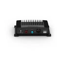
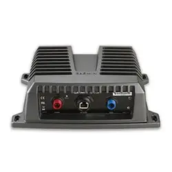
Connecting the Device to Power
WARNING
When connecting the power cable, do not remove the in-line fuse holder. To prevent the possibility of personal
injury or product damage caused by fire or overheating, the appropriate fuse must be in place as indicated in
the product specifications. Connecting the power cable without the appropriate fuse in place voids the product
warranty.
1 Route the cables using the appropriate tie wraps, fasteners, and sealant to secure the cables along the route
and through any bulkheads or to the deck.
NOTE: If necessary, the power cable can be extended (Power Cable Extensions, page5).
2 Connect the bare-wire end of the power cable to your power source and to ground.
NOTE: If you have both a 12 Vdc and a 24 Vdc system on the vessel, you should connect the device to the
24Vdc system for the best performance.
3 Apply dielectric grease to the connector on the power cable.
4 Align the notch on the end of the power cable with the POWER port on the device, and press the cable into
place.
5 Tighten the locking ring.
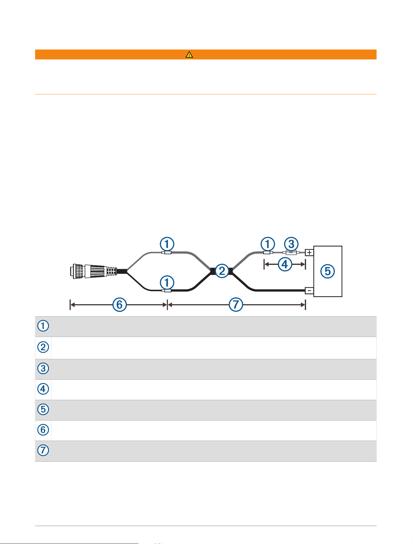
Power Cable Extensions
If necessary, you can extend the power cable using the appropriate wire gauge for the type of power source and
the length of the extension. Use marine-grade connectors or solder and water-resistant heat-shrink tubing when
extending the power wires.
Splice
Extension wires, based on the type of power source and the length of the extension (Power Cable
Extension Wire Gauge Table, page6)
Fuse
20.3cm (8in.)
Power source
20.3cm (8in.)
11m (36 ft.) maximum extension
5
Power Cable Extension Wire Gauge Table
To find the wire gauge you should use, cross-reference the length of the extension with the voltage of your
power supply.
24 Vdc 12 Vdc
Up to 4.6m (15 ft.) 10AWG (5.26mm
2
) 4AWG (21.15mm
2
)
Up to 7m (23 ft.) 8AWG (8.37mm
2
) 2AWG (33.63mm
2
)
Up to 11m (36 ft.) 6AWG (13.30mm
2
) 0 (1/0)AWG (53.48mm
2
)
Grounding the Sonar Module
The ground post is located to the right of the power supply connector.
Connect the ground post to the boat water ground circuit.
NOTE: The boat battery ground is an acceptable alternative if your vessel does
not have a designated water ground circuit.
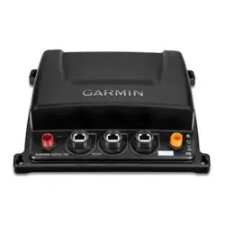
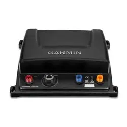
Networking Considerations
This device uses Garmin BlueNet networking technology, and is compatible with both Garmin BlueNet devices
and Garmin Marine Network devices. For more information about Garmin BlueNet technology, including best
practices for constructing a network including both Garmin BlueNet devices and Garmin Marine Network
devices, go to garmin.com/manuals/bluenet.
Before connecting this device to the network, observe the following considerations:
• If your boat is equipped with a Garmin BlueNet chartplotter, you should connect the GSD 28 device to an open
network port on the Garmin BlueNet chartplotter or the Garmin BlueNet 20 switch, using the included Garmin
BlueNet cable.
• If your boat is equipped with a Garmin BlueNet chartplotter and uses a Garmin BlueNet 30 gateway to
connect Garmin Marine Network devices, you should connect the GSD 28 device to the Garmin BlueNet side
of your network, if possible, for the best performance and to best support future updates.
• If your boat is equipped with only Garmin Marine Network devices, you must use the Garmin Marine Network
adapter cable to connect the GSD 28 device to your network. If a Garmin Marine Network adapter cable is not
supplied in the product box, you can purchase one from your local Garmin dealer (part number 010-12531-01)
or online at garmin.com/accessories/GMNAdapterCable .
Connecting to a Garmin BlueNet Network
1 Route the Garmin BlueNet cable to the GSD 28 device and to your Garmin BlueNet chartplotter or Garmin
BlueNet 20 switch.
2 Connect the Garmin BlueNet cable to the network port on the GSD 28 device.
3 Connect the other end of the Garmin BlueNet cable to any open network port on your Garmin BlueNet
chartplotter or the Garmin BlueNet 20 switch.
4 Tighten the locking rings on the connectors.
Connecting to a Garmin Marine Network
1 Route the Garmin BlueNet cable to the GSD 28 device and to your Garmin Marine Network chartplotter or
GMS
™
10 port expander.
2 Connect the Garmin BlueNet cable to the network port on the GSD 28 device.
3 Connect the other end of the Garmin BlueNet cable to the Garmin Marine Network adapter cable.
4 Connect the Garmin Marine Network adapter cable to an open network port on your Garmin Marine Network
chartplotter or the GMS 10 port expander.
5 Tighten the locking rings on the connectors.
6

Manually Configuring a Transducer
Before you can manually configure a transducer, you must connect it to the sonar module using a wiring
method that allows for manual configuration (Connecting a Transducer for Manual Configuration, page4).
1 On a chartplotter connected to the same network as the sonar module, from a sonar view, select Options >
Sonar Setup > Installation > Transducers.
2 Select the GSD 28 sonar module.
3 Select Manual Configuration.
4 If more than one transducer is connected to the sonar module, select an option:
• To configure the transducer connected to the terminals labelled LOW, select Low.
• To configure the transducer connected to the terminals labelled HIGH, select High.
5 Select Manual Enabled to turn on manual configuration.
6 Set the parameters for your transducer.
7 Select Done.
Manual Transducer Configuration Parameters
NOTICE
If parameters are set incorrectly, manual transducer configuration may damage your transducer. If necessary,
you should contact your transducer's manufacturer to verify the correct configuration parameters.
Impedance: The transducer's minimum impedance, in ohms.
Max. Transmit Power: The transducer's maximum transmit power, in watts.
Nominal Freq.: The transducer's nominal frequency, in kHz. If your transducer doesn't have a nominal frequency,
set it to any frequency within its range. This will automatically set a frequency preset for this transducer.
CHIRP: Turn on if configuring a CHIRP transducer.
Lower 3dB Freq.: The lower frequency limit of CHIRP sweeps, in kHz.
Upper 3dB Freq.: The upper frequency limit of CHIRP sweeps, in kHz.
Transducer Wiring Diagrams
You can use these diagrams to identify the connection points for your transducer wires on the GSD 28 terminal
block. Locate your transducer model in the wire color tables (Transducer Wire Color Tables, page9) for more
information.
NOTE: For better visibility, the wiring block label is duplicated in the diagrams below. The GSD 28 device has one
terminal block label, placed in front of the terminal block.
7
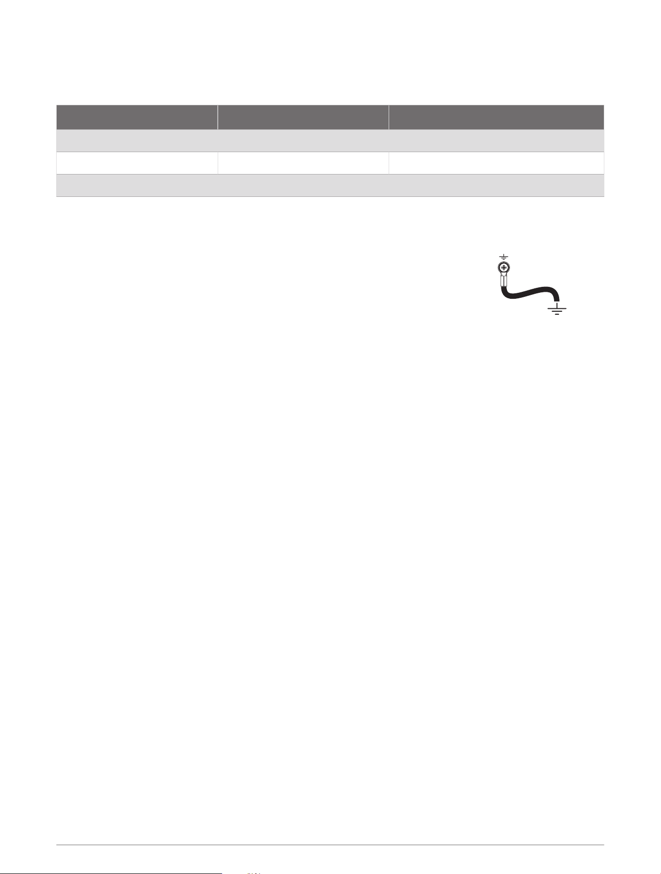
Single-Element Transducers
You can connect a single-element transducer to the terminals labelled LOW or HIGH, regardless of nominal
frequency. To ensure proper transducer identification and safe operation, you must connect each single-
element transducer to its own set of terminals.
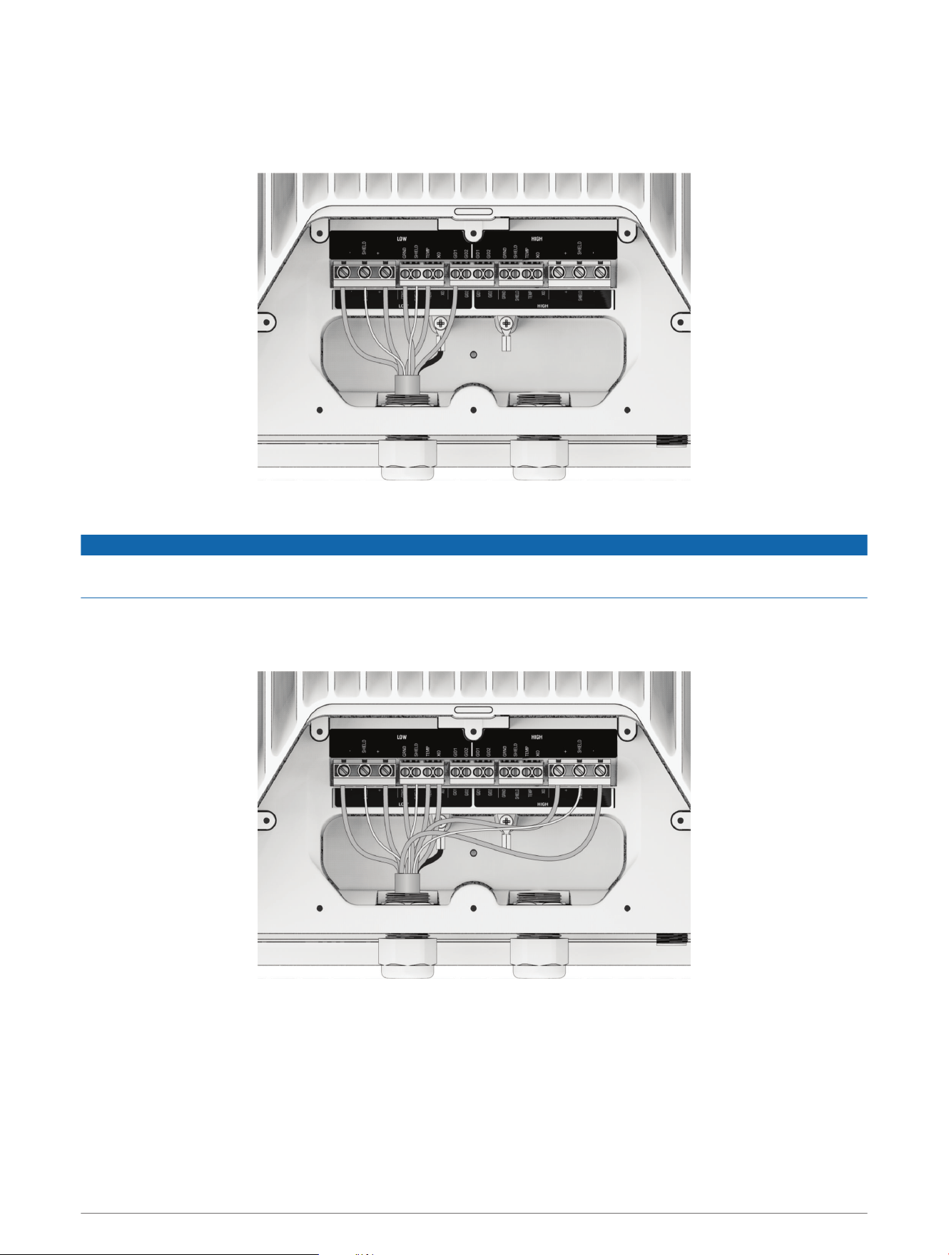
Dual-Element Transducers
NOTICE
Connecting the high-frequency wires to the low-frequency terminal block, or the low-frequency wires to the
high-frequency terminal block, damages the device and the transducer.
For dual-element transducers, the low-frequency element wires must be connected to the terminals labelled
LOW and the high-frequency element wires must be connected to the terminals labelled HIGH. Ground (GRND),
temperature (TEMP), XID and GID wires can be connected to either set of terminals.
8
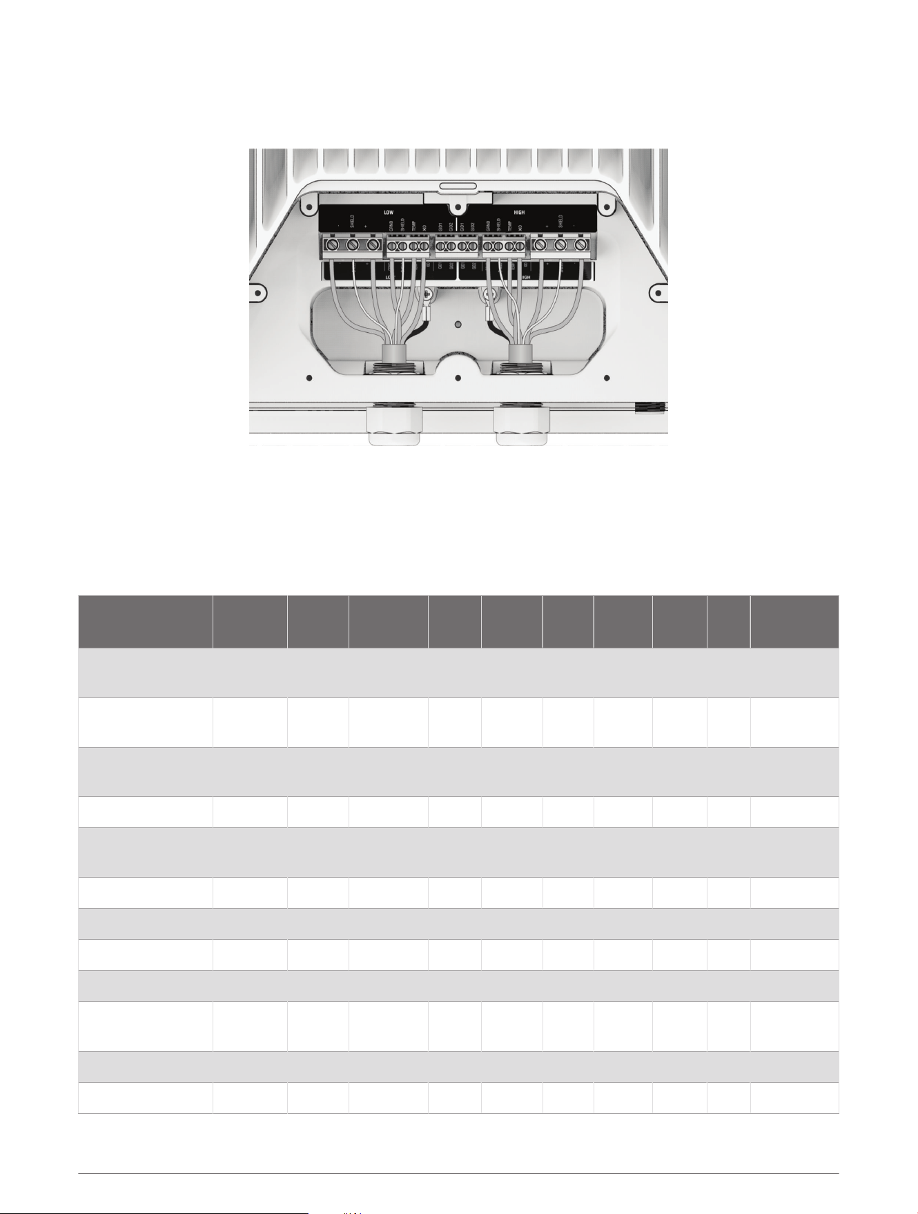
Two Single-Element Transducers
To ensure proper transducer identification and safe operation, you must connect each single-element
transducer to its own set of terminals.
Transducer Wire Color Tables
Single-Element Transducers
You can connect a single-element transducer to the terminals labelled LOW or HIGH, regardless of nominal
frequency. To ensure proper transducer identification and safe operation, you must connect each single-
element transducer to its own set of terminals.
Transducer
Model
+ SHIELD − GRND SHIELD TEMP XID GID1 GID2
Ground
Post
Garmin GT12M-
THF
Red N/A Black Bare N/A White N/A Yellow N/A N/A
Garmin GT15M-
THF
Red N/A Black Bare N/A White N/A Yellow N/A N/A
Garmin GT17M-
THF
Red N/A Black Bare N/A White Orange Yellow N/A N/A
Airmar TM185M Blue Bare Black Brown N/A White Orange N/A N/A Bare
Airmar B175L
Blue/
White
Bare
Black/
White
Brown N/A White Orange N/A N/A Bare
Airmar B175M Blue Bare Black Brown N/A White Orange N/A N/A Bare
Airmar B175H Blue Bare Black Brown N/A White Orange N/A N/A Bare
Airmar TM150M Blue N/A Black Brown N/A White Orange N/A N/A Bare
Airmar B150M Blue N/A Black Brown N/A White Orange N/A N/A Bare
Airmar B75L
Blue/
White
Bare
Black/
White
Brown N/A White Orange N/A N/A Bare
Airmar B75M Blue Bare Black Brown N/A White Orange N/A N/A Bare
Airmar B75H Blue Bare Black Brown N/A White Orange N/A N/A Bare
9

Dual-Element Transducers
Dual-element transducer wires must be connected to the specified terminals.
10

Transducer Model LOW +
LOW
SHIELD
LOW − GRND SHIELD TEMP XID GID1 GID2 HIGH +
HIGH
SHIELD
HIGH −
Ground
Post
Airmar 509LHW
Blue/
White
1
Bare
Black/
White
Brown Bare White Orange N/A N/A Blue Bare Black Bare
Airmar R509LH
Blue/
White
1
Bare
Black/
White
Brown Bare White Orange N/A N/A Blue Bare Black Bare
Airmar R509LM
Blue/
White
1
Bare
Black/
White
Brown Bare White Orange N/A N/A Blue Bare Black Bare
Airmar
CM599LHW
Blue/White Bare
Black/
White
Brown Bare White Orange N/A N/A Blue Bare Black Bare
Airmar CM599LH Blue/White Bare
Black/
White
Brown Bare White Orange N/A N/A Blue Bare Black Bare
Airmar CM599LM Blue/White Bare
Black/
White
Brown Bare White Orange N/A N/A Blue Bare Black Bare
Airmar R599LH
Blue/
White
1
Bare
Black/
White
Brown Bare N/A Orange N/A N/A Blue Bare Black Bare
Airmar R599LM
Blue/
White
1
Bare
Black/
White
Brown Bare N/A Orange N/A N/A Blue Bare Black Bare
Airmar R109LHW
Blue/
White
1
Bare
Black/
White
Brown Bare White Orange N/A N/A Blue Bare Black Bare
Airmar R109LM
Blue/
White
1
Bare
Black/
White
Brown Bare White Orange N/A N/A Blue Bare Black Bare
Airmar R109LH
Blue/
White
1
Bare
Black/
White
Brown Bare White Orange N/A N/A Blue Bare Black Bare
Airmar R111LH
Blue/
White
1
Bare
Black/
White
Brown Bare White Orange N/A N/A Blue Bare Black Bare
Airmar M265LH
Blue/
White
1
Bare
Black/
White
Brown N/A White Orange N/A N/A Blue Bare Black Bare
Airmar B265LM
Blue/
White
1
Bare
Black/
White
Brown N/A White Orange N/A N/A Blue Bare Black Bare
Airmar B265LH
Blue/
White
1
Bare
Black/
White
Brown N/A White Orange N/A N/A Blue Bare Black Bare
Airmar TM265LM
Blue/
White
1
Bare
Black/
White
Brown N/A White Orange N/A N/A Blue Bare Black Bare
Airmar TM265LH
Blue/
White
1
Bare
Black/
White
Brown N/A White Orange N/A N/A Blue Bare Black Bare
Airmar PM265LM Blue/White Bare
Black/
White
Brown N/A White Orange N/A N/A Blue Bare Black Bare
1
Yellow before 11/20/10
11
Transducer Model LOW +
LOW
SHIELD
LOW − GRND SHIELD TEMP XID GID1 GID2 HIGH +
HIGH
SHIELD
HIGH −
Ground
Post
Airmar PM265LH Blue/White Bare
Black/
White
Brown N/A White Orange N/A N/A Blue Bare Black Bare
Airmar B275LHW Blue/White Bare
Black/
White
Brown N/A White Orange N/A N/A Blue Bare Black Bare
Airmar
PM411LWM
Blue/White Bare
Black/
White
Brown N/A White Orange N/A N/A Blue Bare Black Bare
Status LED
After the sonar module is installed, it turns on when the chartplotter is turned on. The status LED on the sonar
module indicates its operational status.
LED Color State Status
Red Solid The sonar module is booting.
Green Flashing
The sonar module is connected to a chartplotter and is
operating properly.
Red Flashing
The sonar module is turned on, but is not connected to a chart
plotter, or is waiting to connect to a chartplotter.
Orange Flashing A software update is in progress.
Red/Green Flashing The sonar module is in test mode.
Red/Orange Flashing The sonar module terminal block lid is open.
Red
Flashes twice followed by a 3-
second pause
Other sonar failure. Check all connections.
Red
Flashes three times followed
by a 3-second pause
The transducer is not detected by the sonar module.
Red
Flashes four times followed by
a 3-second pause
The sonar module input voltage is below the minimum required
input voltage.
Red
Flashes five times followed by
a 3-second pause
The sonar module input voltage is above the maximum allowed
input voltage.
12

Specifications
Size L x W x H: 270.65 x 366.55 x 101mm (10.66 x 14.43 x 3.98in.)
Weight 6.41 kg (14.125 lb.)
Case material Fully gasketed, aluminum and steel housing with plastic access panel .
Water rating IEC 60529 IPX7
2
Temperature range From 5 to 158°F (from -15 to 70°C)
Power input From 10 to 32Vdc
Power usage 120W max.
Fuse 15 A (fast-acting, blade type)
Compass safe distance 190cm (75in.)
Sounder power From 25 to 3,000W (RMS)
3
Frequency From 25 to 250kHz (dependent on transducer)
Depth 3,048m (10,000ft.)
4
Data output Garmin BlueNet network
連絡地址
製造銷售:台灣國際航電股份有限公司
聯絡地址:新北市汐止區樟樹二路 68 號
電 話:(02)2642-8999
客服專線:(02)2642-9199
2
The device withstands incidental exposure to water of up to 1m for up to 30min. For more information, go to www.garmin.com/waterrating.
3
Dependent on transducer rating and depth.
4
Maximum depth dependent on transducer, water salinity, bottom type, and other water conditions.
13
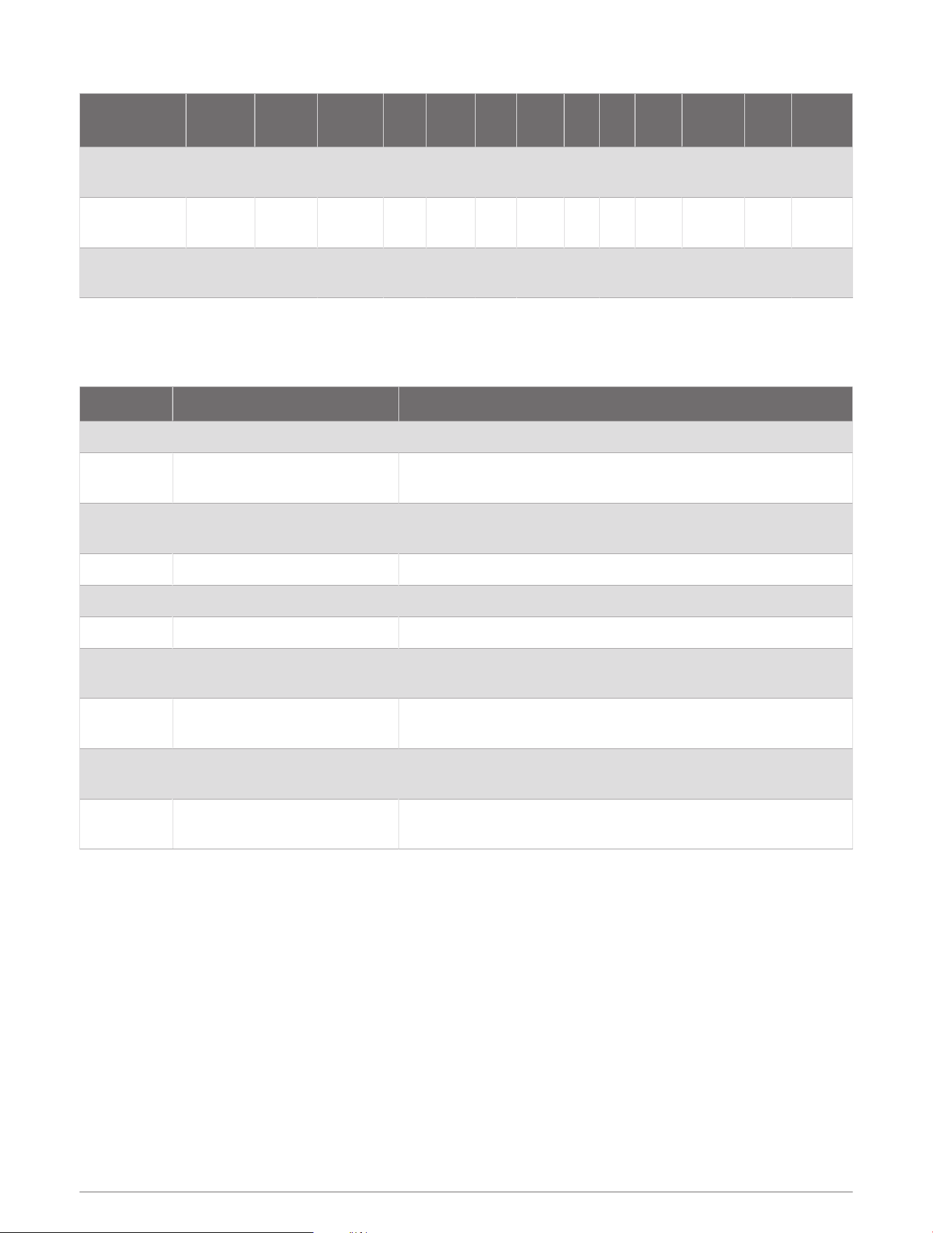
物質宣言
部件名称
有毒有害物质或元素
铅 汞 镉 六价铬 多溴联苯
多溴二苯
醚
邻苯二甲酸
二(2-乙基
己)酯
邻苯二甲
酸丁苄酯
邻苯二甲
酸二丁酯
邻苯二甲
酸二异丁
酯
印刷电路板组
件
金属零件
电缆 电缆组件
连接器
塑料和橡胶零
件
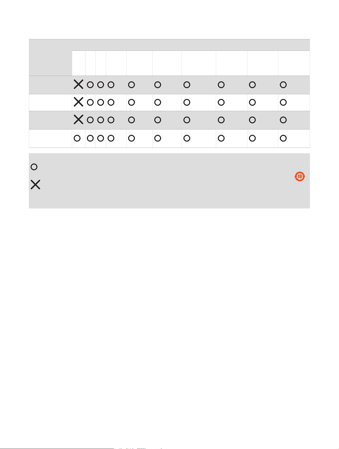
本表格依据 SJ/T11364 的规定编制。
: 代表此种部件的所有均质材料中所含的该种有害物质均低于
(GB/T26572) 规定的限量
: 代表此种部件所用的均质材料中, 至少有一类材料其所含的有害物质高于
(GB/T26572) 规定的限量
* 该产品说明书应提供在环保使用期限和特殊标记的部分详细讲解产品的担保使用条件。
产品
© 2023 Garmin Ltd. or its subsidiaries
Garmin
®
and the Garmin logo are trademarks of Garmin Ltd. or its subsidiaries, registered in the USA and other countries. GSD and Garmin BlueNet
™
are trademarks of
Garmin Ltd. or its subsidiaries. These trademarks may not be used without the express permission of Garmin.
Airmar
™
is a trademark of Airmar Technology Corporation.
© 2023 Garmin Ltd. or its subsidiaries
support.garmin.com