2 Deutsch
Allgemeine Hinweise
Lesen Sie vor dem Umbau diese Montageanleitung
und handeln Sie danach.
Bewahren Sie die Montageanleitung für späteren Gebrauch oder
für Nachbesitzer auf.
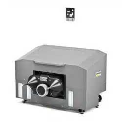
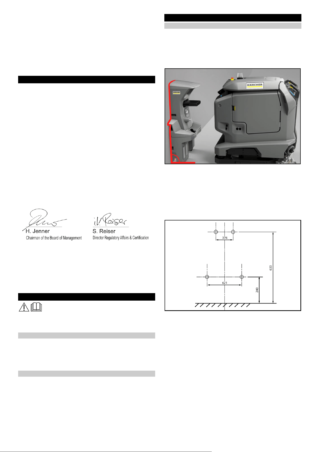
Beschreibung
Die Dockingstation versorgt das Gerät mit Elektrizität zum Laden
der Batterien und mit Frischwasser. Nach dem Andocken wird
der Schmutzwassertank entleert und gespült. Der Frischwasser-
tank wird nachgefüllt und die Batterien werden geladen.
Sicherheitshinweise
● Beachten Sie die örtliche Vorschriften zur Abwasserbehand-
lung und -entsorgung.
● Das Wassersystem ist auf maximal 1 MPa ausgelegt. Bauen
Sie bei Überschreitung in die Zuleitung einen Druckbegrenzer
ein.
● Achten Sie darauf, dass das Netzkabel nicht mit den rotieren-
den Bürsten, Rädern oder Rollen des Geräts in Berührung
kommen.
Montage
Dockingstation montieren
Hinweis
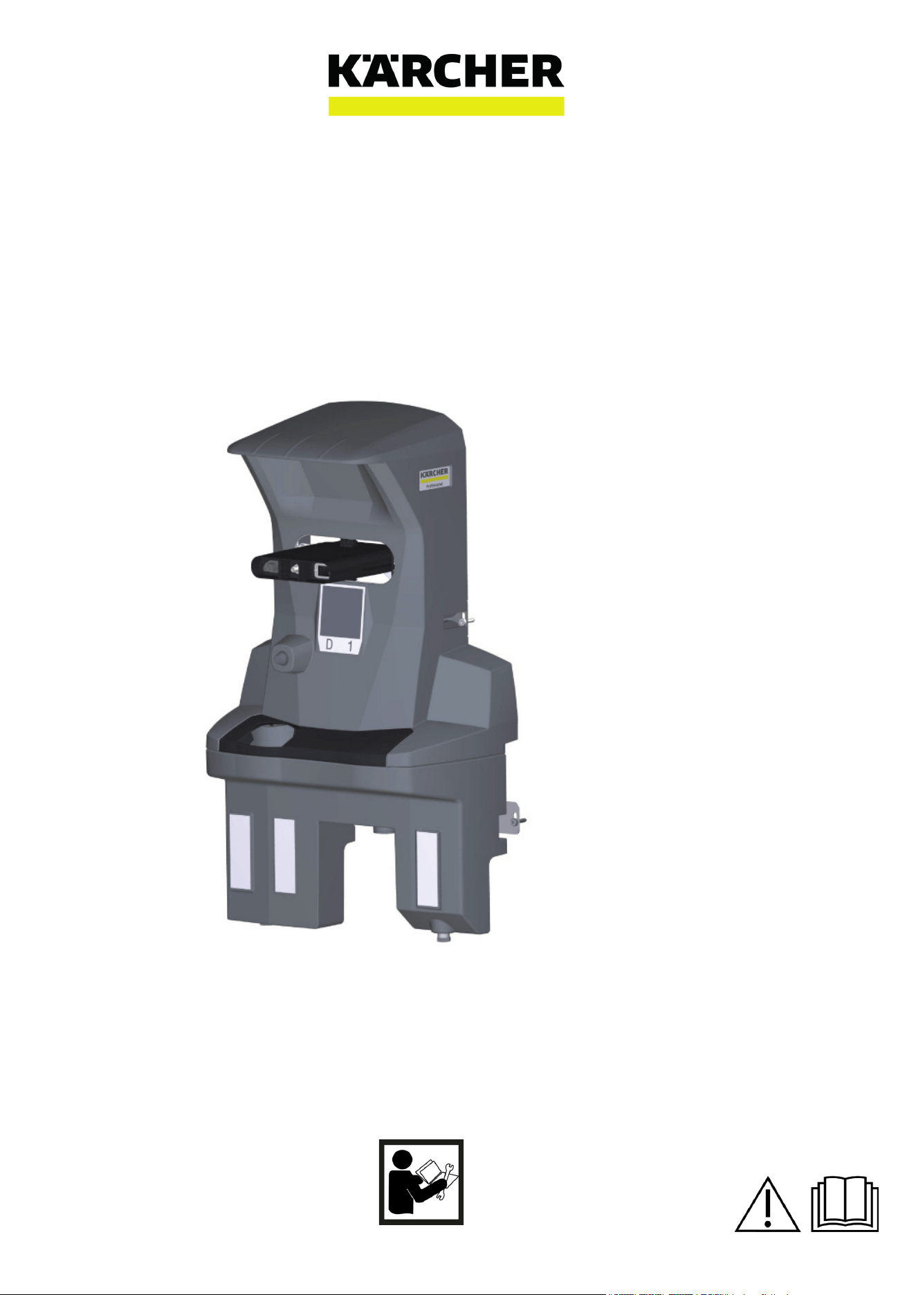
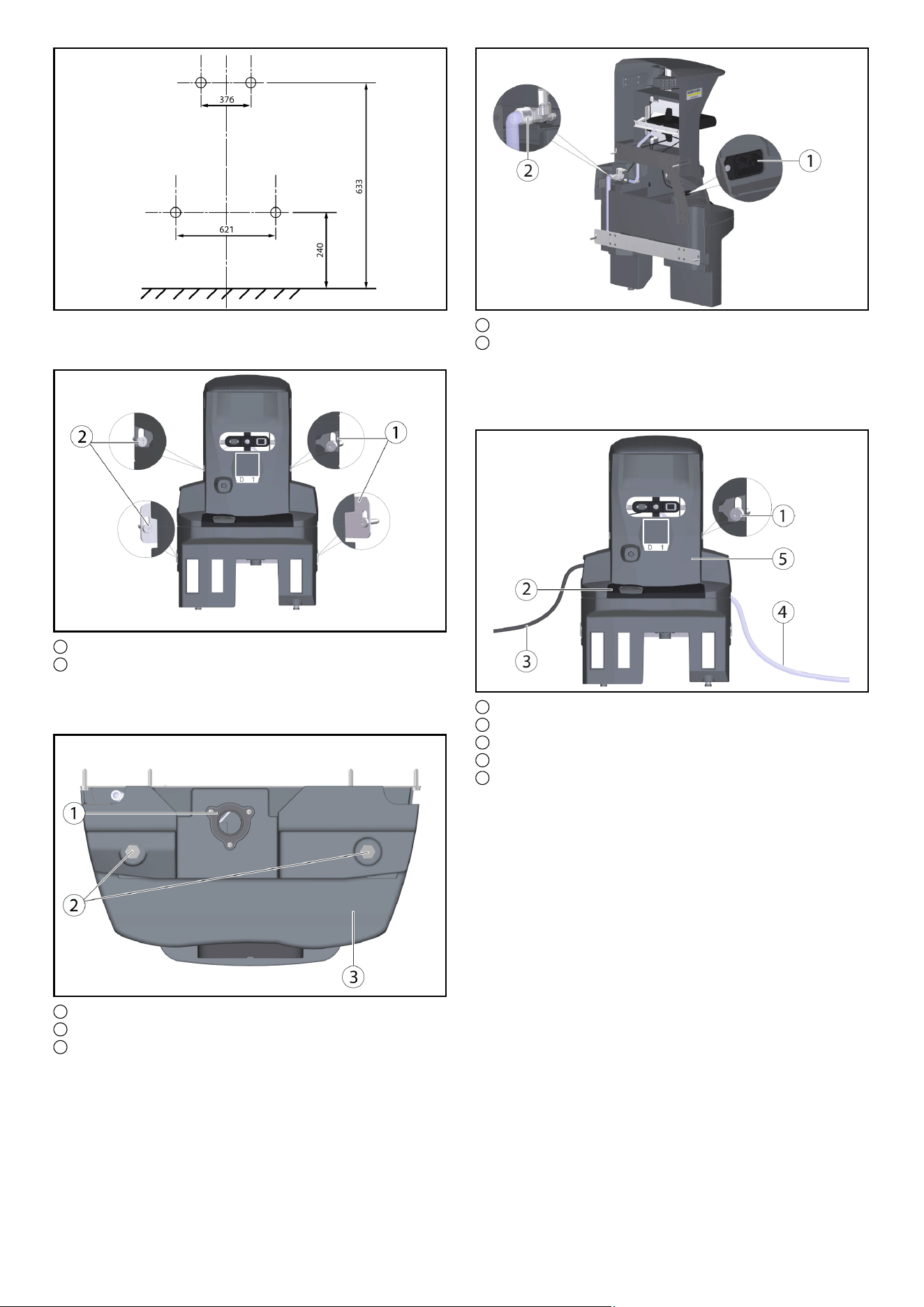
Die Dockingstation wird mit 4 Schrauben an der Wand befestigt.
Der Durchmesser der Schrauben muss 6 mm betragen.
Hinweis
Bitte beachten Sie bei der Auswahl des Standorts für die Do-
ckingstation folgendes:
●
● Die Dockingstation muss im rechten Winkel zur Bodenfläche
montiert sein.
● Die Rückseite der Dockingstation muss an der Wand anlie-
gen, die Rückseite darf nicht offen sein.
● Der Aufbau der Dockingstation sollte auf einer ebenen Fläche
erfolgen.
● Die Dockingstation sollte an einer geschlossenen Fläche ste-
hen, da sonst ein fehlerfreies Andocken nicht möglich ist.
● Die Dockingstation darf nicht nach einer Rampe aufgebaut
werden.
● Das beigelegte Befestigungsmaterial verwenden, oder ent-
sprechend der Beschaffenheit der Wand besorgen.
● Die Dockingstation an die Wand stellen und Bohrungen mar-
kieren.
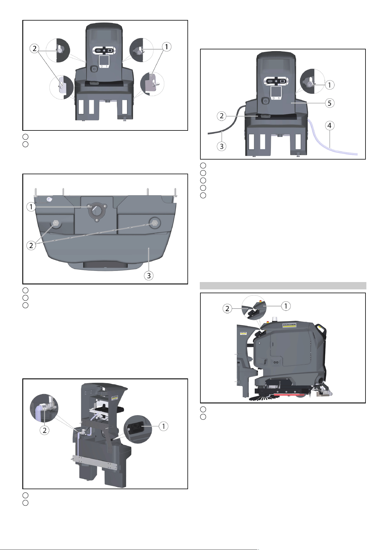
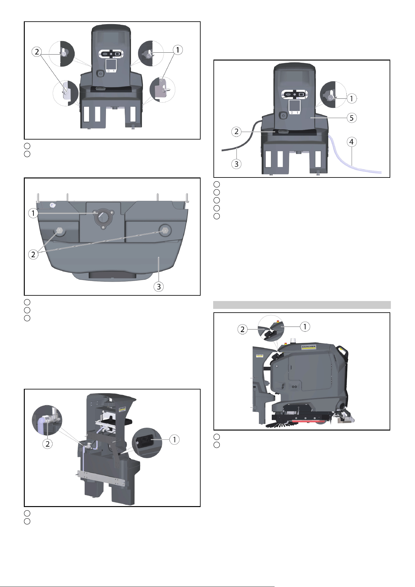
1 Halteblech (2x)
2 6kt-Schraube M6x40 (4x)
● Die Dockingstation an die Wand stellen und die Schrauben
nur leicht eindrehen.
● Die Dockingstation ausrichten und an der Wand befestigen.
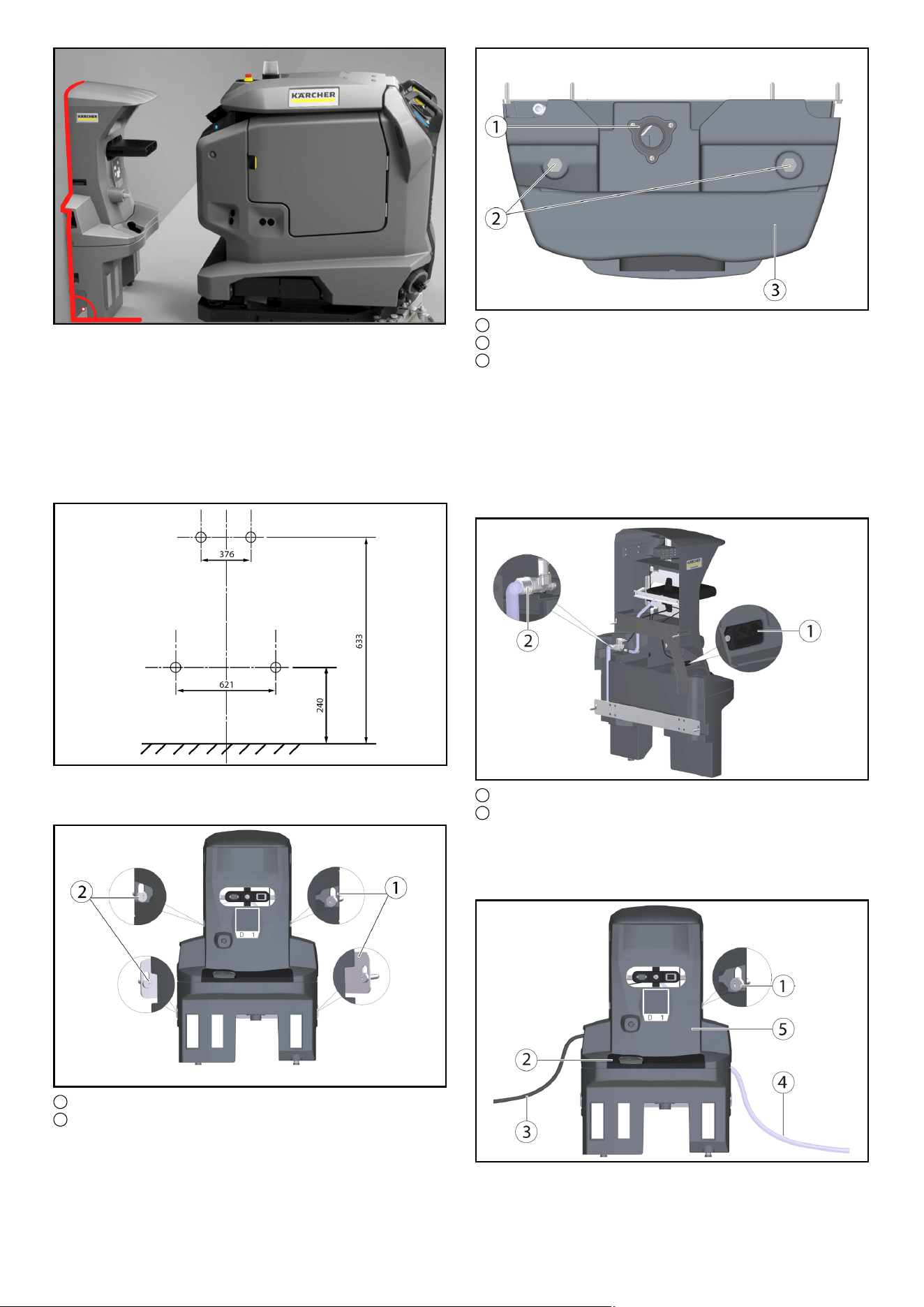
1 Ablass Schmutzwasser
2 Fuß Dockingstation
3 Unterteil Dockingstation
● Mit Hilfe von mitgelieferten U-Scheiben (5 Stück pro Schraub-
fuß), an die Bodenverhältnisse anpassen.
Hinweis
Zusätzlich werden noch 4 weitere U-Scheiben beigelegt.
● Die Schrauben auf beiden Seiten festziehen.
● Den Ablass für Schmutzwasser mit der Abwasser-Entsor-
gungseinrichtung verbinden.Örtliche Vorschriften zur Abwas-
serbehandlung und -entsorgung beachten.
Deutsch 3
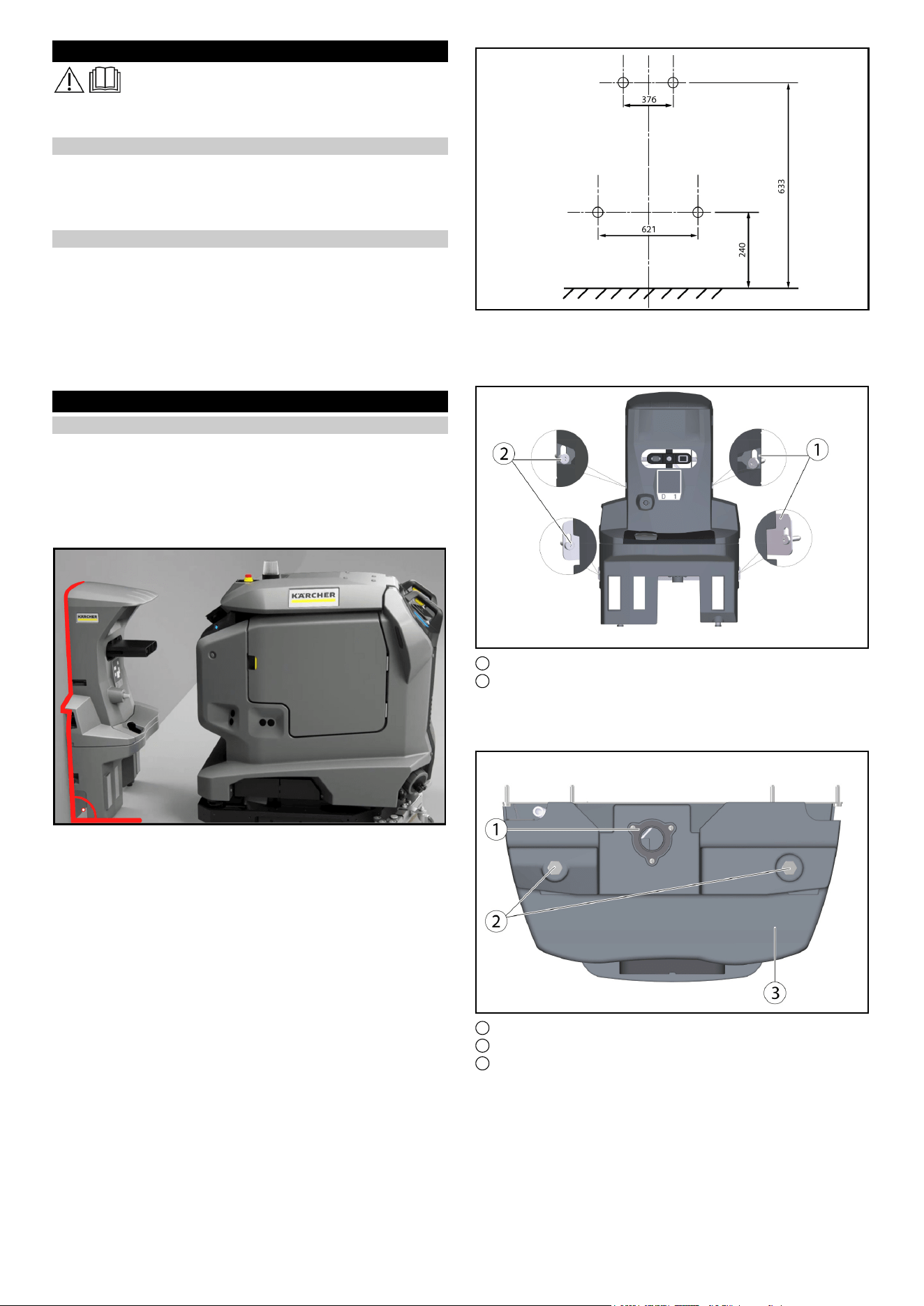
1 Kaltgerätesteckdose
2 Wasseranschluss
● Den beiliegenden Schlauch mit dem Wasseranschluss ver-
binden.
Durchflussrichtung (Pfeil) beachten.
● Das beiliegende Netzkabel mit der Kaltgerätesteckdose am
Gerät verbinden.
1 Schraube
2 Abdeckung
3 Netzkabel
4 Schlauch
5 Oberteil Dockingstation
● Die Schrauben auf beiden Seiten festziehen.
● Die Abdeckung anbringen.
● Den Schlauch mit der Wasserversorgung verbinden. Maximal
zulässigen Wasserdruck in Kapitel „Technische Daten“ be-
achten. Bei Bedarf einen Druckminderer in die Zuleitung ein-
bauen.
● Den Netzstecker in die Steckdose stecken.Die Steckdose
muss mit einem Fehlerstromschutzschalter mit einem länder-
spezifisch zulässigen Auslösestrom abgesichert sein.
● Auf Funktion prüfen.
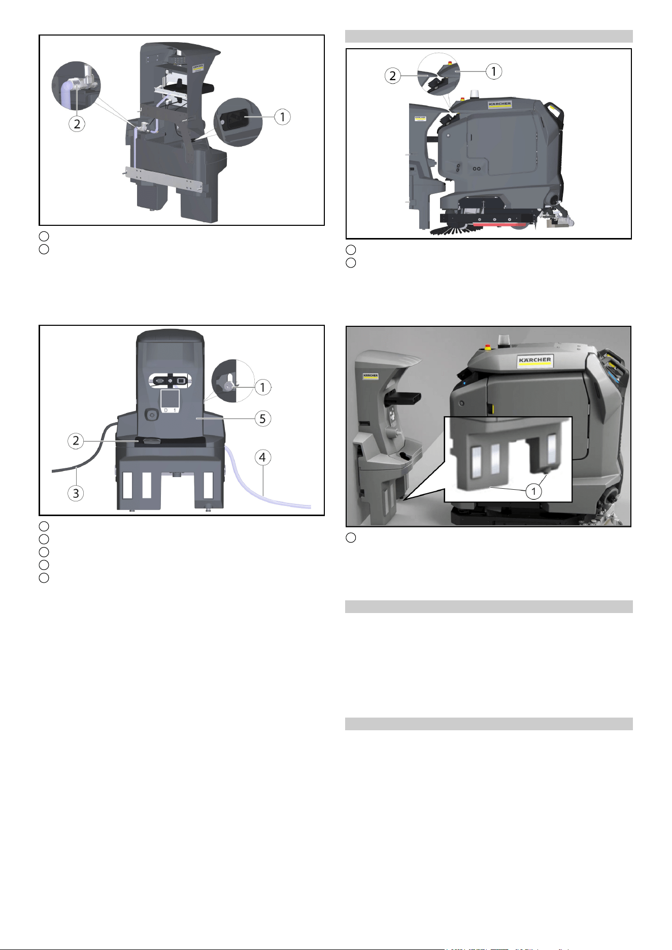
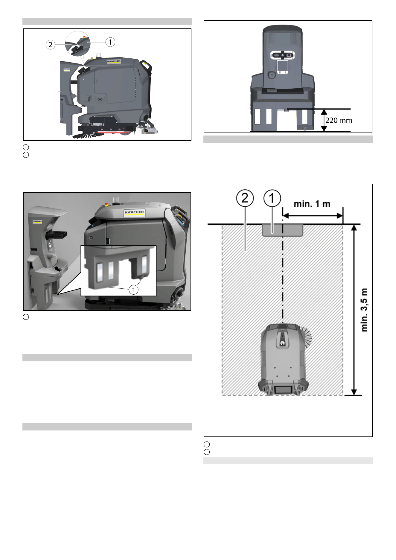
Höhe einstellen
1 Deckel Schmutzwassertank
2 Keil, Dockingstation
● Das Gerät vor die Dockingstation fahren.
● Die Höhenausrichtung prüfen: Die Spitze des Keils an der Do-
ckingstation muss die Schräge am Deckel des Schmutzwas-
sertanks auf halber Höhe treffen
●
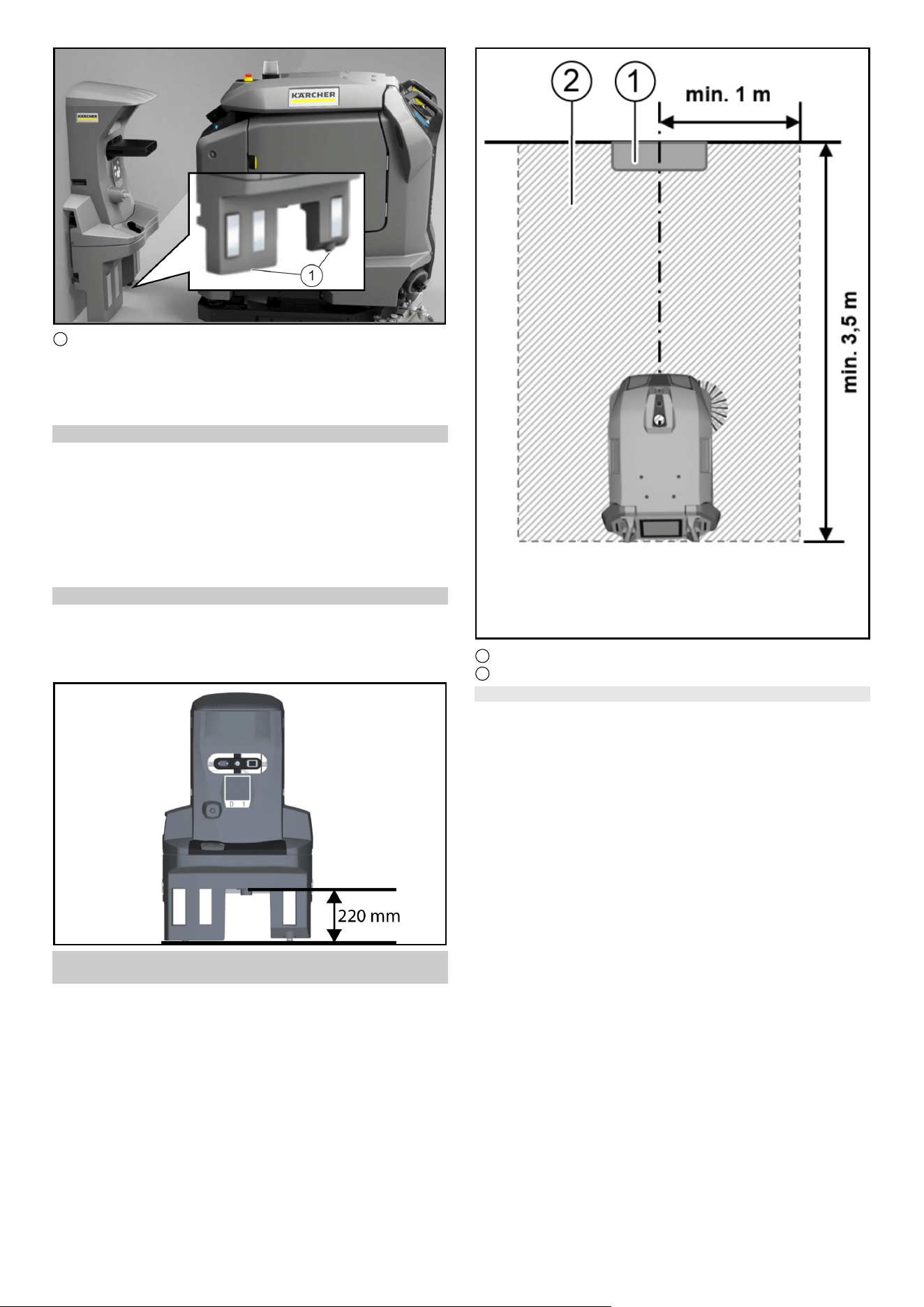
1 Stellschrauben
● Die Dockingstation mit den unteren Stellschrauben von der
Höhe so einstellen, dass das der Cliff LiDAR Rammschutz an
dem Gerät mit ca. 5 mm Abstand unter die Dockingstation ein-
fährt.
Höhe korrigieren
1. Die Differenz zur korrekten Einstellung messen.
2. Die 4 Schrauben an der Dockingstation lösen und von der
Wand nehmen.
3. Die Schraubfüße am Unterteil um die Differenz mit Hilfe der U-
Scheiben verstellen(eine U-Scheibe entspricht 2 mm).
4. Die Dockingstation an die Wand stellen und mit den 4 Schrau-
ben fixieren.
5. Die Höhenausrichtung erneut prüfen.
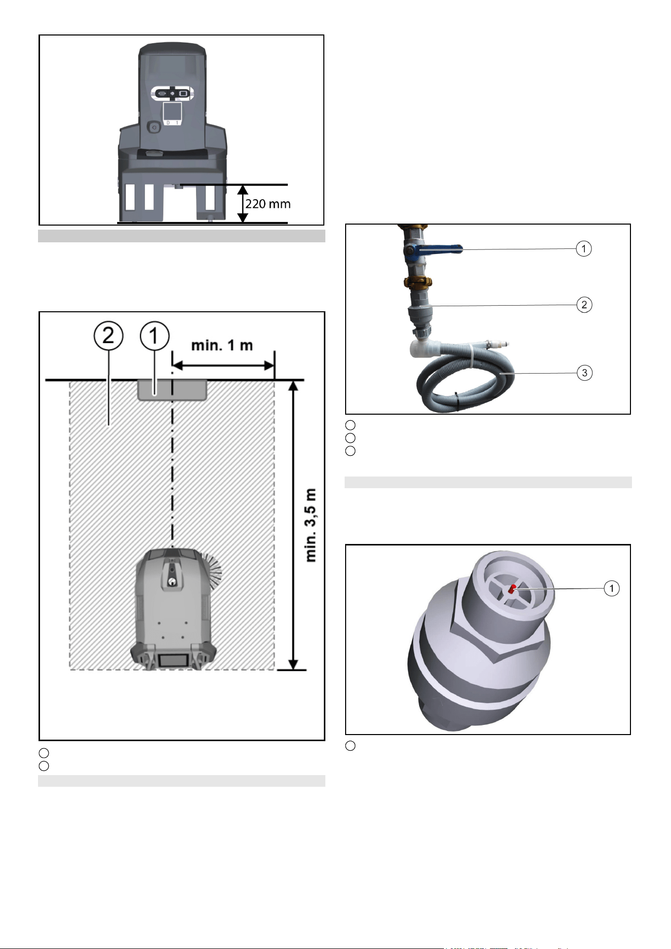
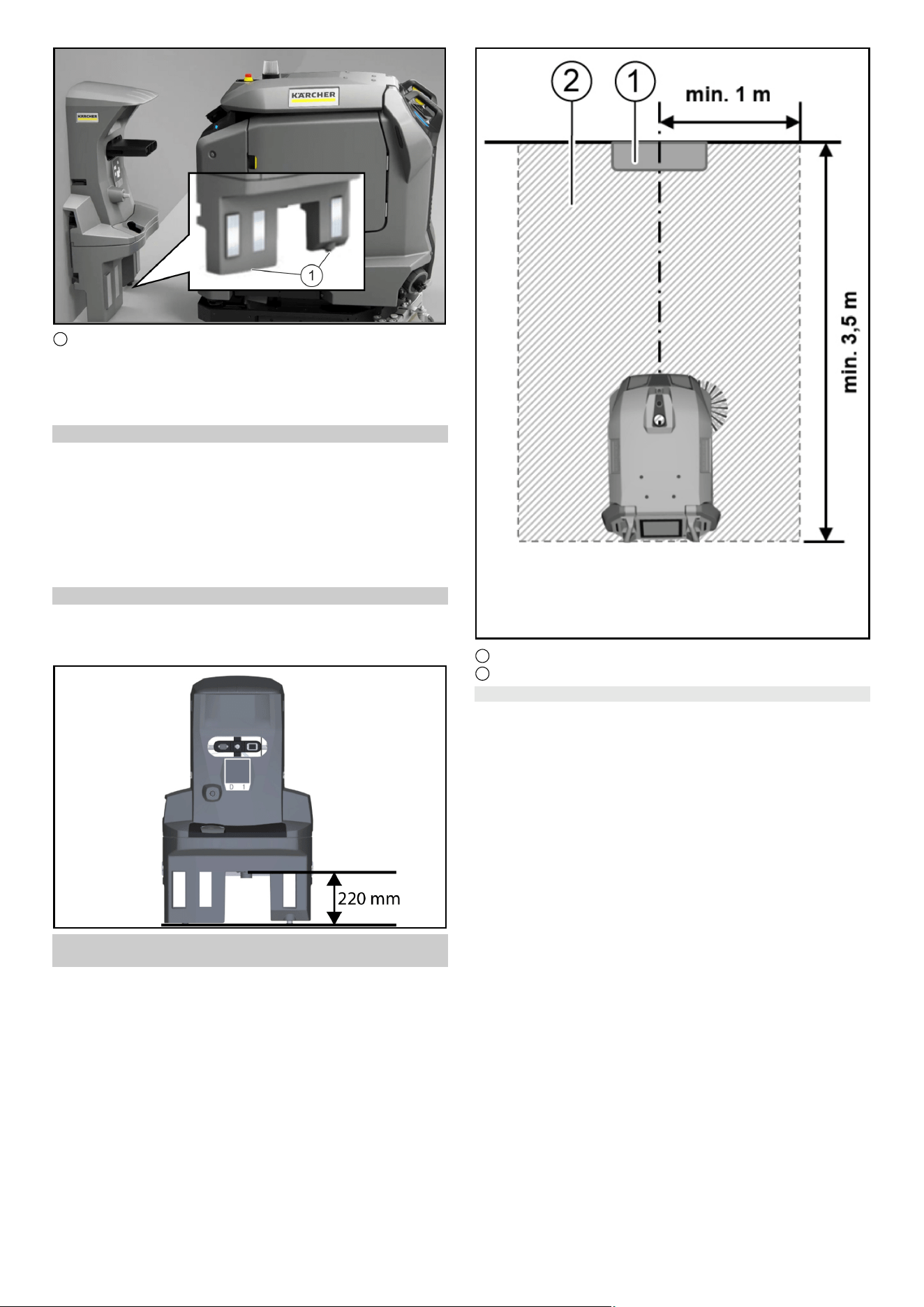
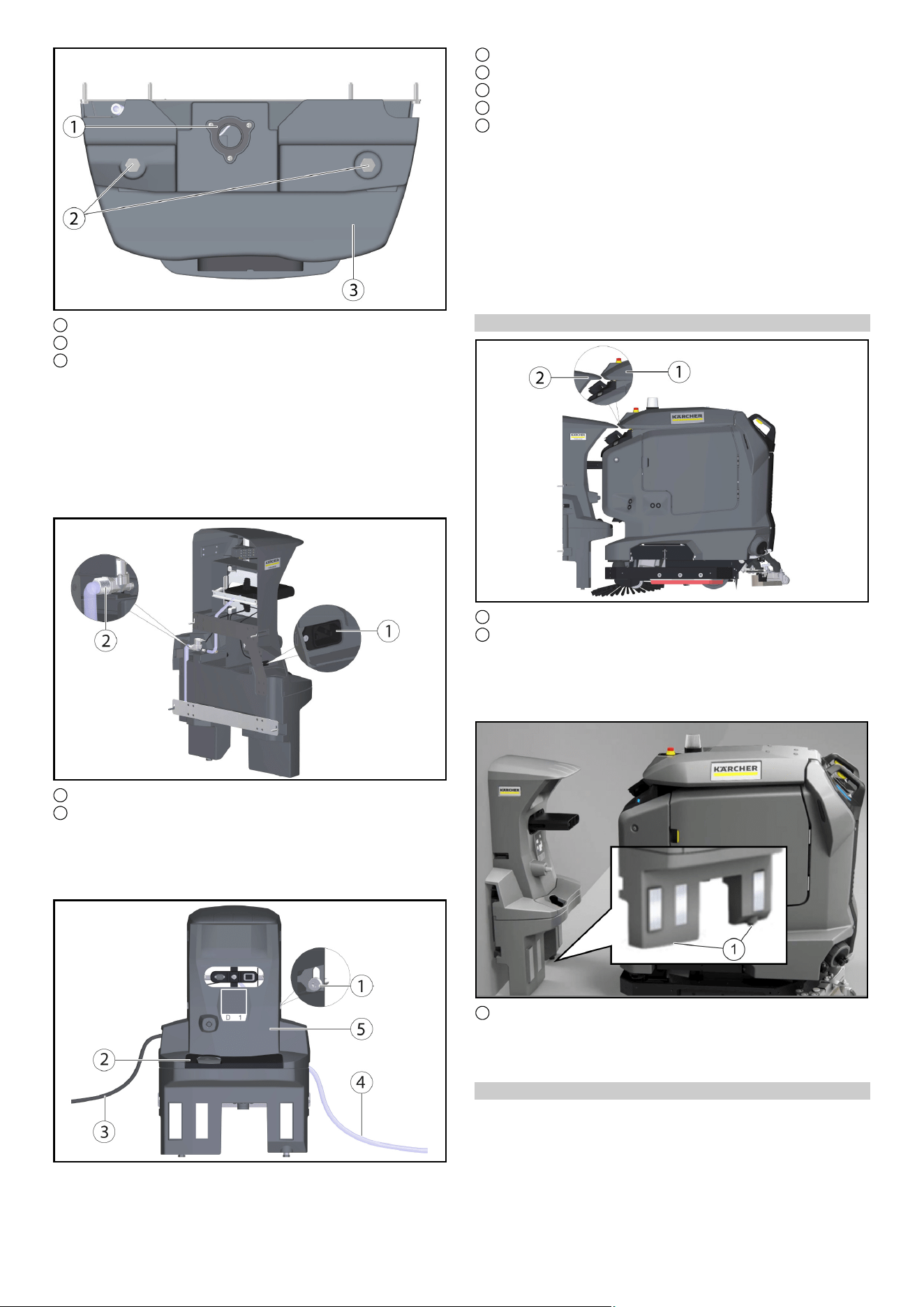
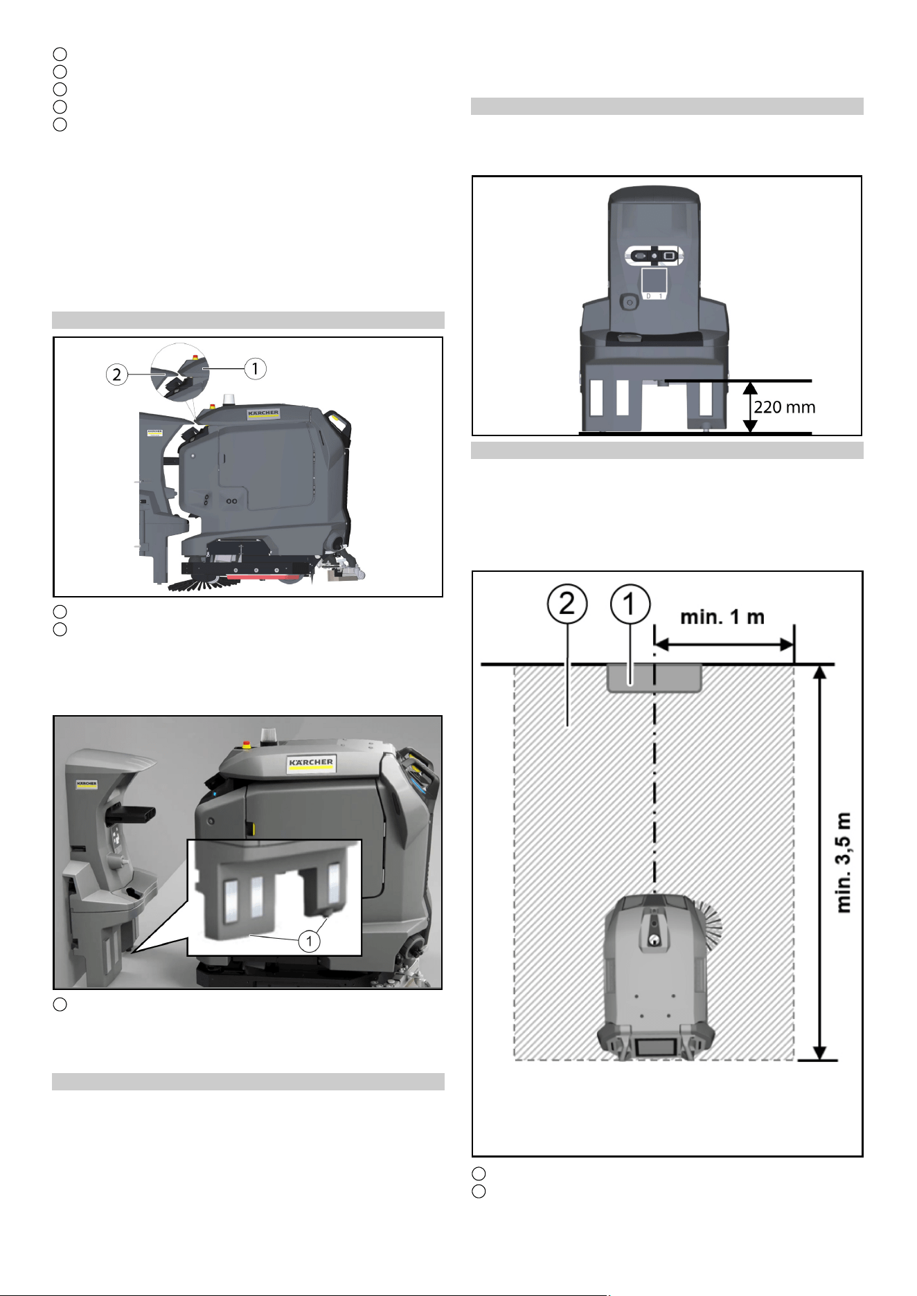
Höhe Abfluss Dockingstation
Hinweis
Beachten Sie, dass der Abstand zwischen dem Boden und der
Höhe des Abflusses der Schmutzwasserwanne 220 mm betra-
gen muss.
4 Deutsch
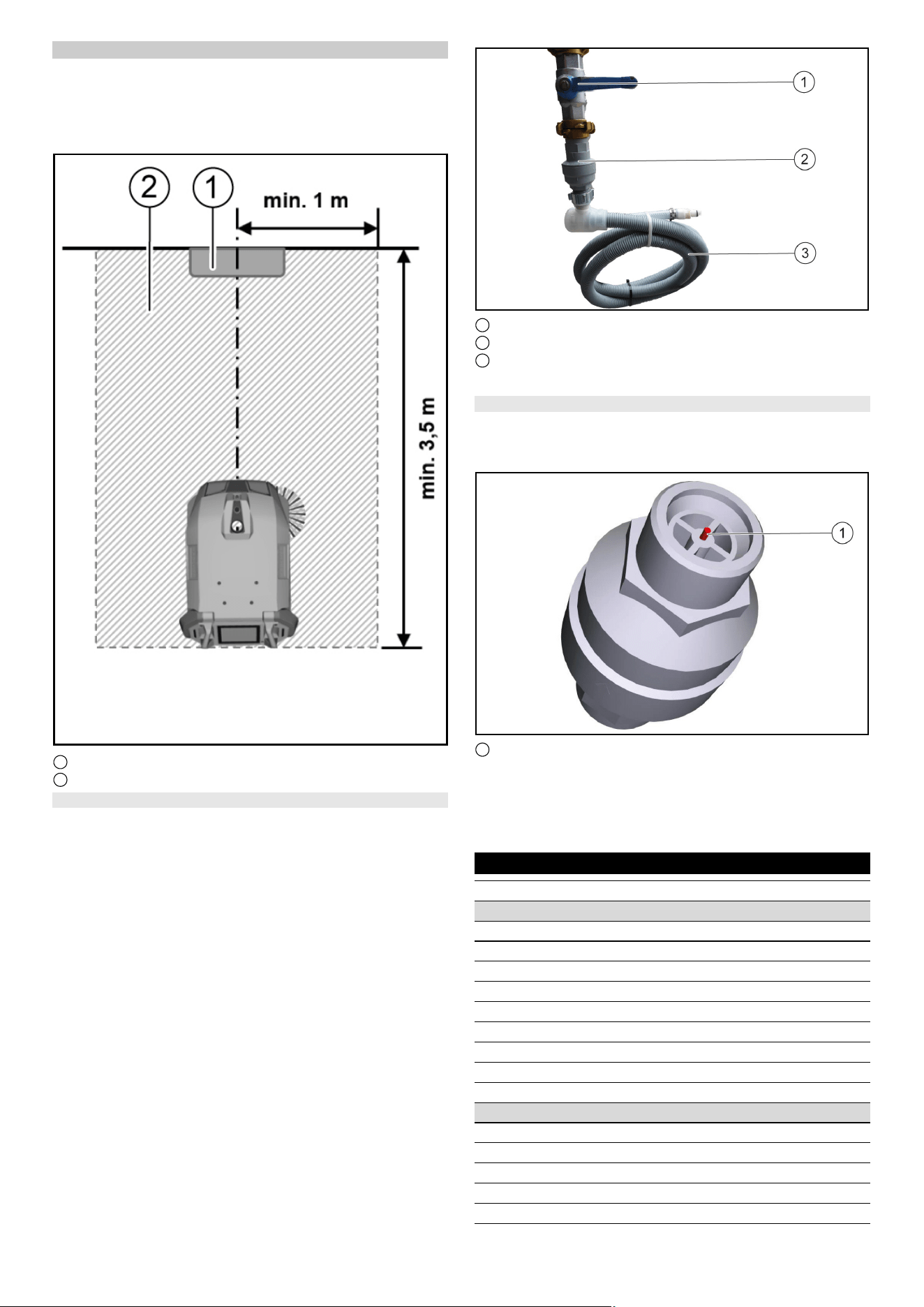
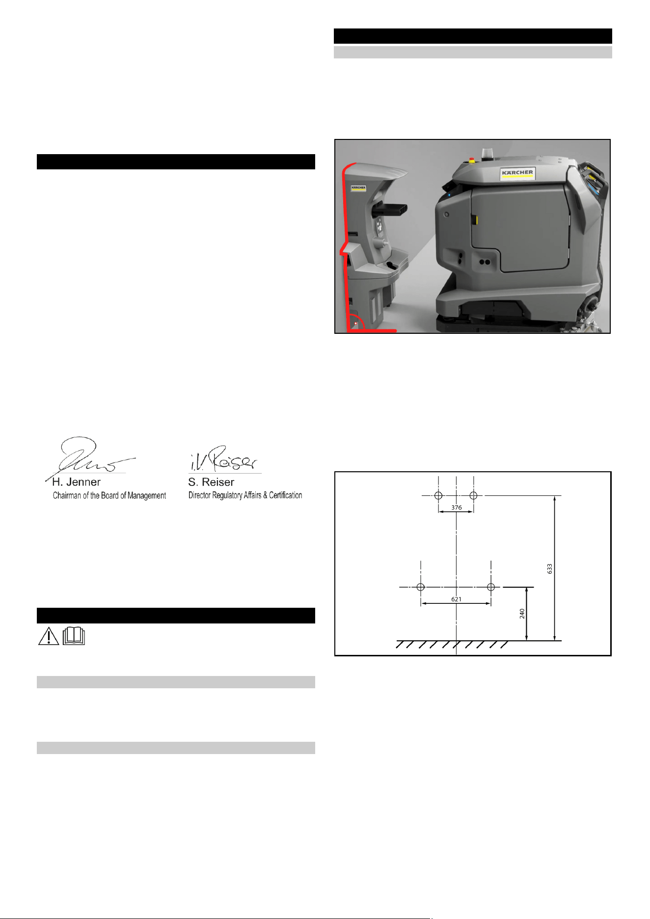
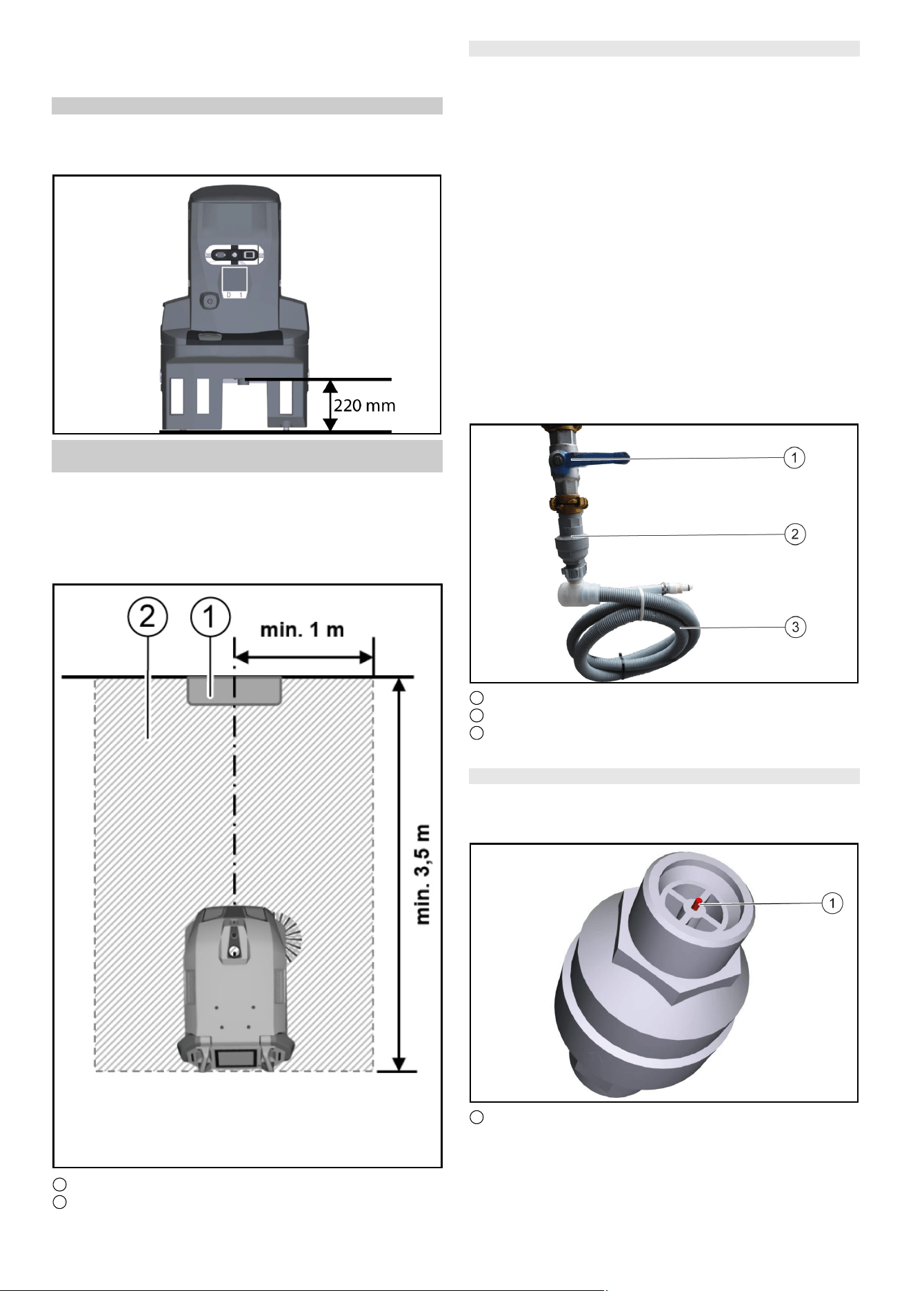
Frei zu haltende Fläche um die Dockingstation
Hinweis
Damit der Roboter an der Dockingstation zuverlässig andocken
kann, muss vor der Dockingstation ausreichend Platz freigehal-
ten werden. Die empfohlene Größe der freizuhaltenden Zone
kann folgender Abbildung entnommen werden.
1 Dockingstation
2 Frei zu haltende Fläche
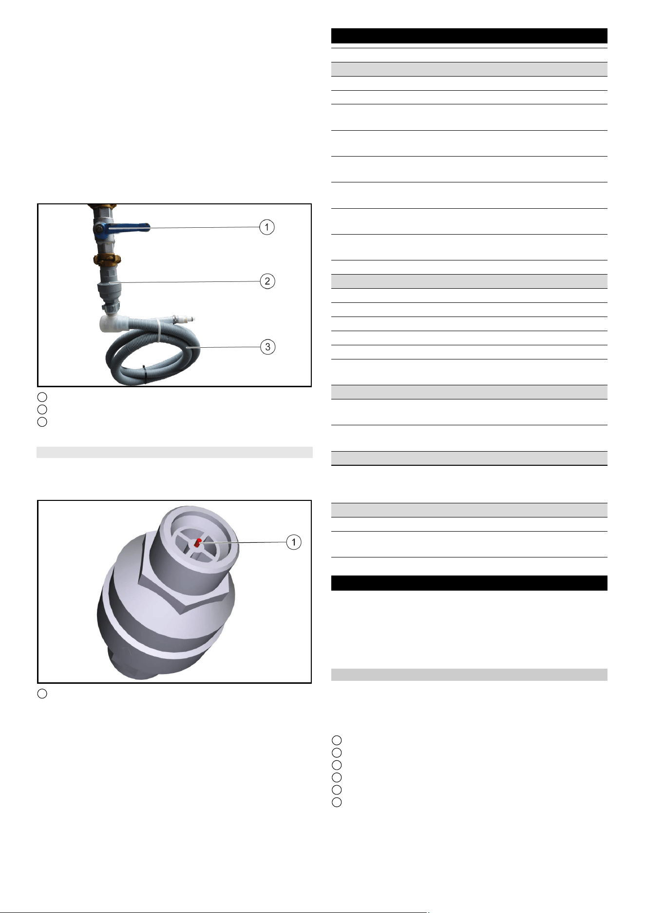
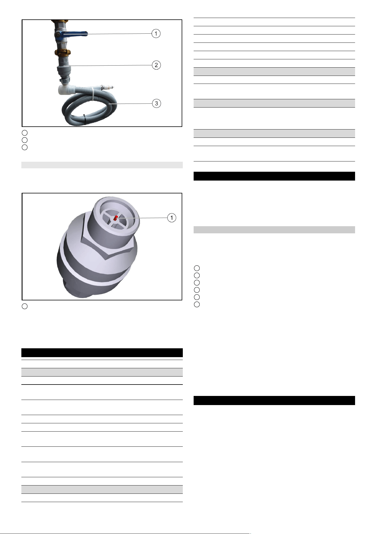
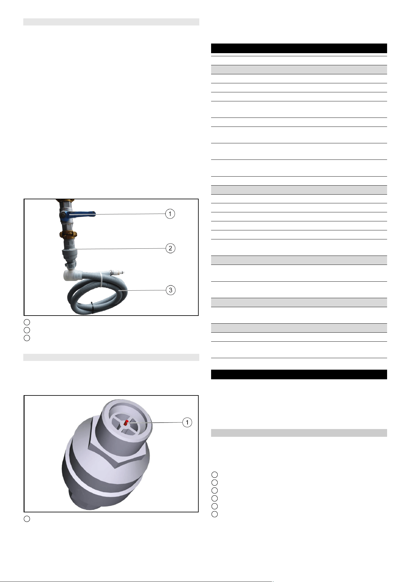
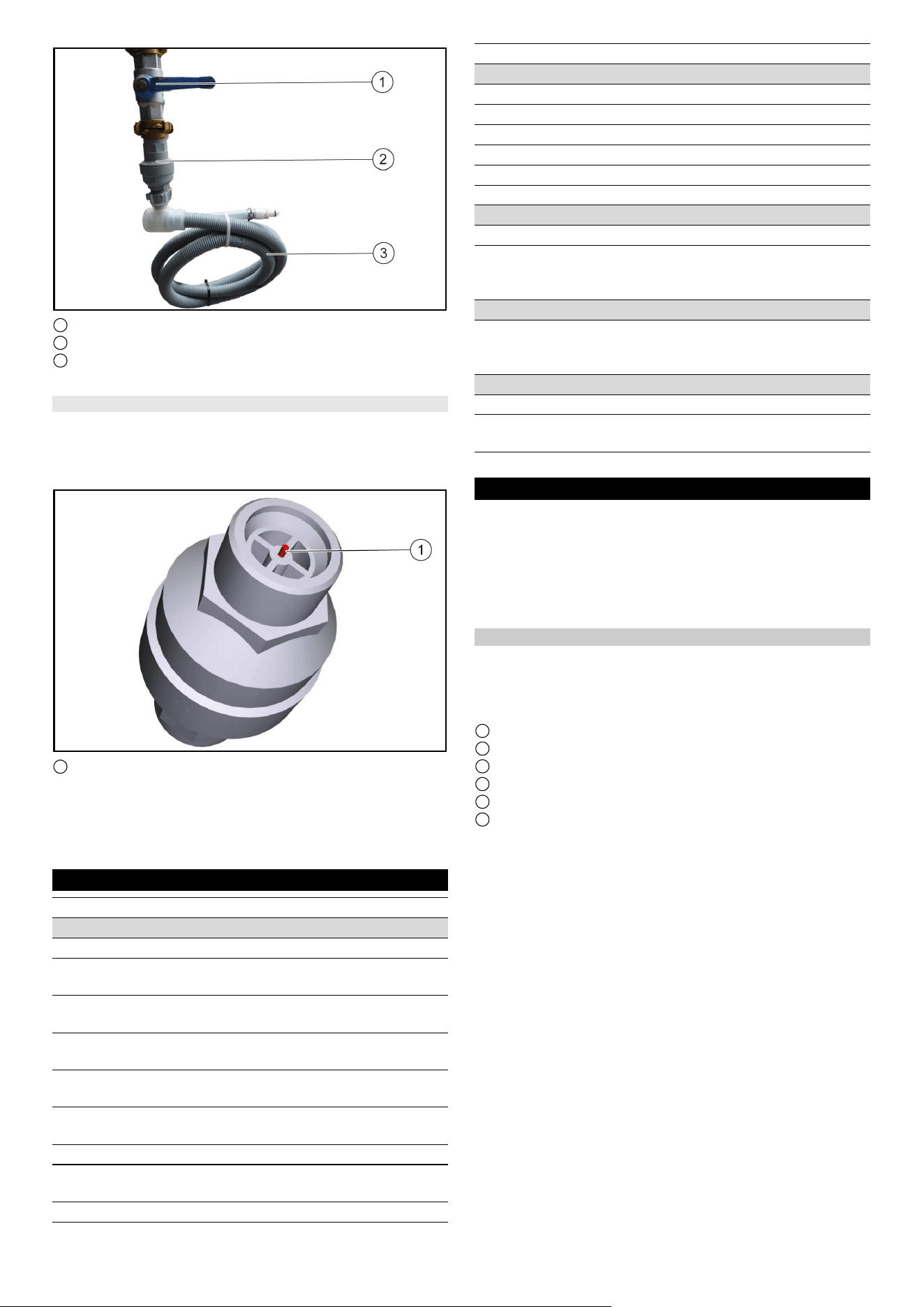
Wasserstoppventil einbauen
Um sicher zu stellen, dass kein Wasser an der Dockingstation
überläuft kann zusätzlich ein Wasserstoppventil eingebaut wer-
den. Das Wasserstoppventil wird zwischen dem Wasserhahn
und dem Aquastopp-Schlauch montiert.
1. Die Wasserzufuhr abstellen.
2. Den Pfeil mit dem mitgelieferten Schraubenschlüssel auf Stu-
fe 8 (40 Liter Wasserdurchlauf) stellen.
Hinweis
Das Wasserstoppventil ist einstellbar von Stufe 1 (5 Liter Was-
serdurchlauf) bis Stufe 10 (50 Liter Wasserdurchlauf) und
schließt automatisch, wenn mehr als die eingestellte Wasser-
menge ohne Unterbrechung durchgeflossen ist.
3. Das obere Ende des Wasserstoppventil am Wasserhahn be-
festigen.
Hinweis
Am Eingang des Wasserstoppventils ist ein nach oben gewölbter
Wasserfilter eingebaut. Sollte der Aquastopp-Schlauch einen Fil-
ter montiert haben muss dieser durch eine Dichtung ersetzt wer-
den, damit die Funktion des Wasserstoppventils gewährleistet
werden kann.
4. Den Aquastopp-Schlauch am Gewindeboden des Wasser-
stoppventils befestigen.
1 Wasserhahn
2 Wasserstoppventil
3 Schlauch
5. Die Wasserzufuhr wieder aufdrehen.
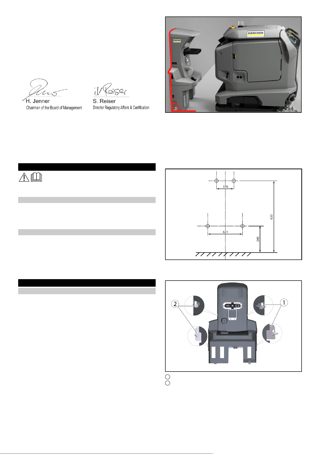
Wasserstoppventil zurücksetzen
1. Die Wasserzufuhr abstellen.
2. Den Aquastopp-Schlauch demontieren.
3. Das Wasserstoppventil abdrehen und den roten Stift eindrü-
cken.
1 Roter Stift
4. Das obere Ende des Wasserstoppventils am Wasserhahn be-
festigen und den roten Stift eindrücken.
5. Den Aquastopp-Schlauch am Gewindeboden des Wasser-
stoppventils befestigen.
6. Die Wasserzufuhr wieder aufdrehen
English 5
Technische Daten
Technische Änderungen vorbehalten.
Pflege und Wartung
GEFAHR
Unabsichtlich anlaufendes Gerät, Berührung stromführen-
der Teile
Verletzungsgefahr, Stromschlag
Trennen Sie vor allen Arbeiten das Gerät von der Dockingstation
oder ziehen Sie den Netzstecker.
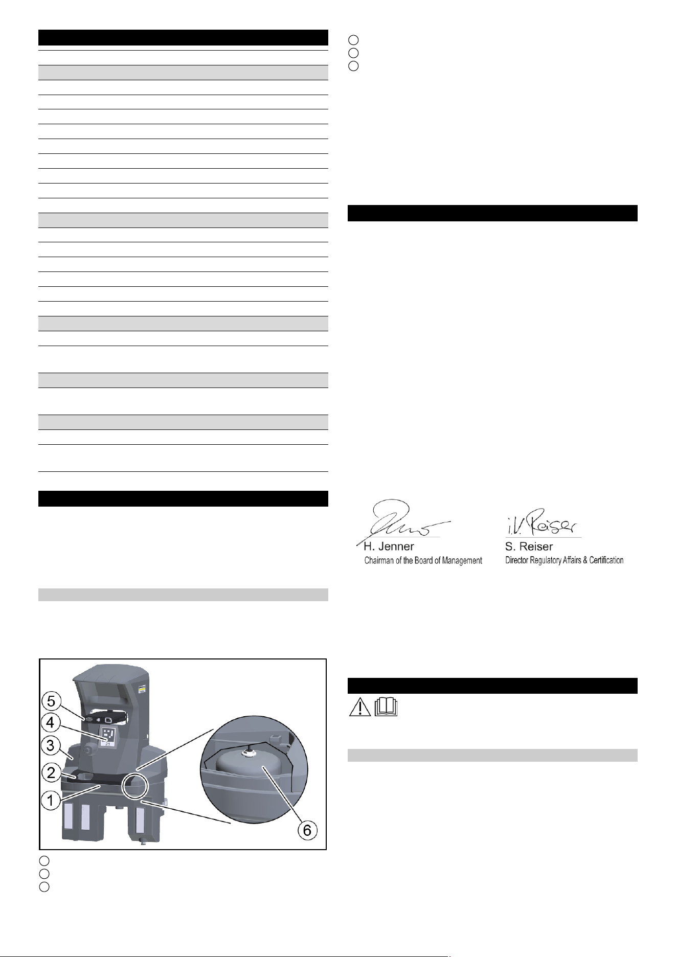
Dockingstation reinigen
몇 WARNUNG
Gefahr durch elektrischen Schlag.
Ziehen Sie vor Arbeiten an der Dockingstation den Netzstecker
aus der Steckdose.
1 Schmutzwasserwanne
2 Abdeckung
3 Dockingstation
4 Positionscode
5 Dockingstößel
6 Schwimmerschalter mit Schwimmer
1. Die Abdeckung abnehmen.
2. Den Schwimmerschalter und Schwimmer prüfen, bei Bedarf
reinigen.
3. Die Schmutzwasserwanne reinigen und mit Wasser spülen.
4. Die Abdeckung anbringen.
5. Den Positionscode mit einem feuchten Tuch reinigen.
6. Den Dockingstößel auf freie Beweglichkeit prüfen.
Hinweis
Für eine geeignete Nutzung der Dockingstation ist eine Freiflä-
che vor der Docking Station 2x2 m
2
vorzusehen
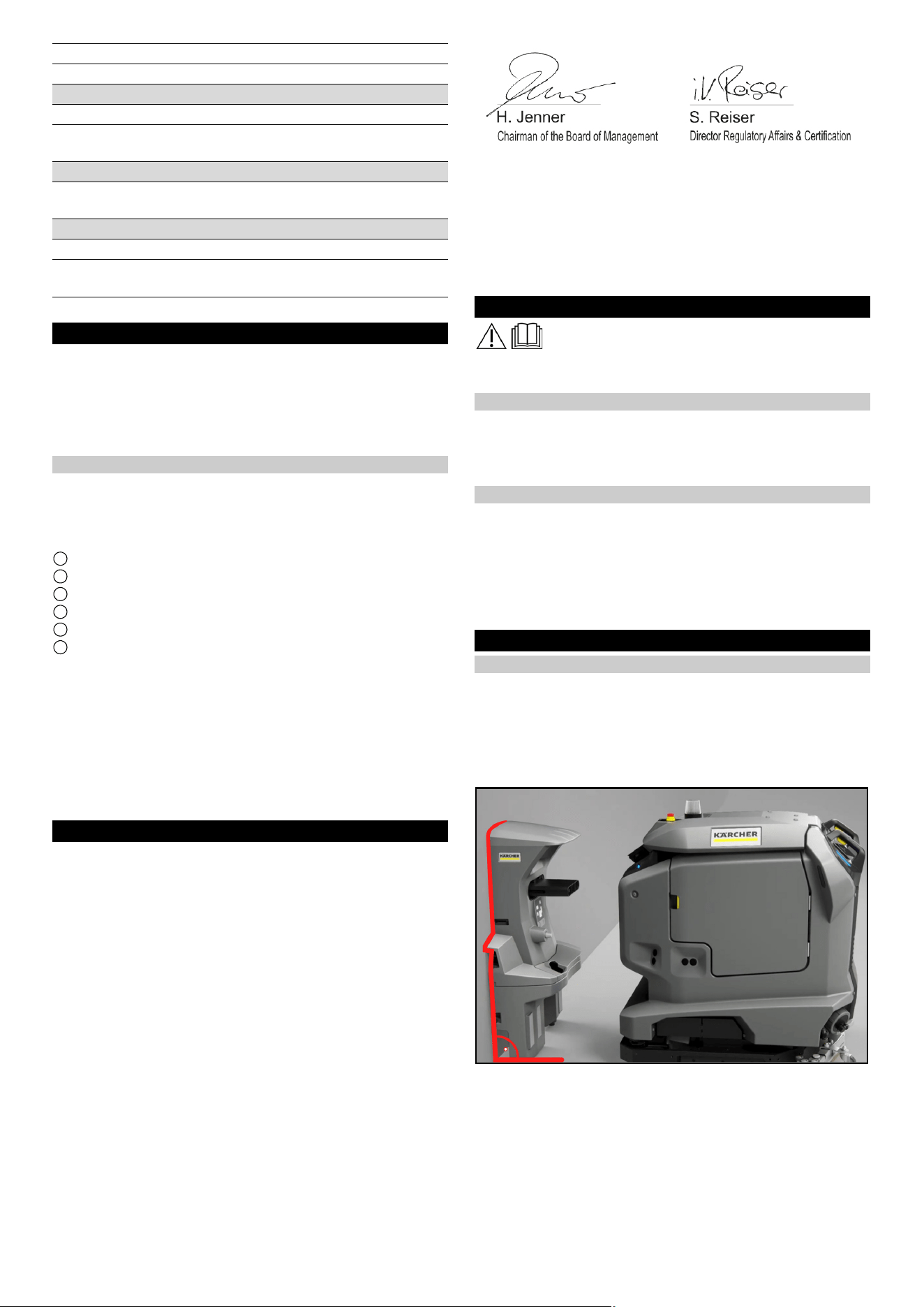
EU-Konformitätserklärung
Hiermit erklären wir, dass die nachfolgend bezeichnete Maschine
aufgrund ihrer Konzipierung und Bauart sowie in der von uns in
Verkehr gebrachten Ausführung den einschlägigen grundlegen-
den Sicherheits- und Gesundheitsanforderungen der EU-Richtli-
nien entspricht. Bei einer nicht mit uns abgestimmten Änderung
der Maschine verliert diese Erklärung ihre Gültigkeit.
Produkt: Kira Docking-Station
Typ: 2.042-xxx
Einschlägige EU-Richtlinien
2006/42/EG (+2009/127/EG)
2014/30/EU
Angewandte harmonisierte Normen
EN 60335-1
EN 60335-2-72
EN IEC 63327
EN IEC 61000-6-2: 2019
EN 61000-6-3: 2007 + A1:2011
Angewandte nationale Normen
-
Die Unterzeichnenden handeln im Auftrag und mit Vollmacht des
Vorstands.
Dokumentationsbevollmächtigter:
S. Reiser
Alfred Kärcher SE & Co. KG
Alfred-Kärcher-Str. 28 - 40
71364 Winnenden (Germany)
Tel.: +49 7195 14-0
Fax: +49 7195 14-2212
Winnenden, 2021/11/01
General notes
Read and adhere to these installation instructions
before conversion.
Keep these installation instructions for future reference or for fu-
ture owners.
Description
The docking station supplies the Device with electricity to charge
the batteries and fresh water. After docking, the waste water tank
is emptied and flushed. The fresh water tank is refilled and the
batteries are charged.
Sharp DELTA Q
Leistungsdaten Gerät
Anzahl Batterien 2 2
Nennspannung, Li-Ion V 25,6 25,6
Batteriekapazität, Li-Ion Ah (5 h) 160 160
Mittlere Leistungsaufnahme W 1600 1600
Leistung Fahrmotor W 2x280 2x280
Leistung Saugturbine W 630 630
Leistung Bürstenantrieb W 600 600
Laufzeit bei voller Batterie h 3,5 3,5
Schutzart IPX3 IPX3
Internes Ladegerät
Nennspannung V 100...240 100...240
Stromaufnahme A <7,5 9,9-4,7
Frequenz Hz 50-60 50-60
Leistung W 760 960
Ladestrom A 30 40
Ladedauer Batterie h 8 5,25
Abwasserleitung
Nennweite Abfluss mm 50 50
Mindestgefälle Abwasserlei-
tung
°1-31-3
Anforderung Hebeeinheit
Förderleistung Schmutzwas-
ser-Hebeanlage
m
3
/h ≥ 6,5 ≥ 6,5
Maße und Gewichte
Gewicht kg 15,2 15,2
Länge x Breite x Höhe mm 1050x650
x350
1050x650
x350
6 English
Safety instructions
● Observe the local waste water treatment and disposal regula-
tions.
● The water system is designed for a maximum of 1 MPa. Install
a pressure limiter in the supply line if the pressure is exceed-
ed.
● Make sure that the mains cable does not come into contact
with the rotating brushes, wheels or rollers of the device.
Installation
Installing the docking station
Note
The docking station is attached to the wall with 4 screws. The di-
ameter of the screws must be 6 mm.
Note
When selecting the location for the docking station, please note
the following:
●
● The docking station must be mounted at right angles to the
floor surface.
● The back of the docking station must be against the wall, the
back must not be open.
● The docking station should be set up on a flat surface.
● The docking station should be placed on a closed surface, oth-
erwise it will not be possible to dock without errors.
● The docking station must not be set up after a ramp.
● Use the enclosed fastening material or obtain fastening mate-
rial according to the condition of the wall.
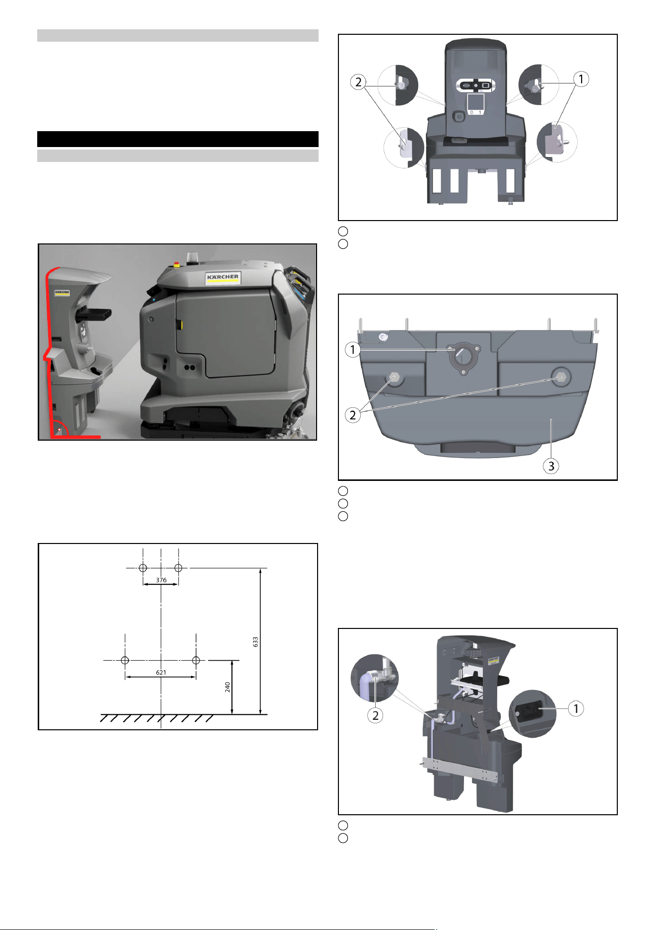
● Place the docking station against the wall and mark holes.
1 Retaining plate (2x)
2 Hexagon screw M6x40 (4x)
● Place the docking station against the wall and screw in the
screws only slightly.
● Align the docking station and attach it to the wall.
1 Drain for waste water
2 Foot Docking Station
3 Docking station lower part
● Adjust to the ground conditions with the help of the supplied
washers (5 per screw foot).
Note
4 more washers are additionally enclosed.
● Tighten the screws on each side.
● Connect the drain for waste water to the waste water disposal
equipment. Observe local regulations for waste water treat-
ment and disposal.
1 Socket for non-heating apparatus
2 Water connection
English 7
● Connect the enclosed hose to the water connection.
Note the flow direction (arrow).
● Connect the enclosed mains cable to the socket for non-heat-
ing apparatus on the unit.
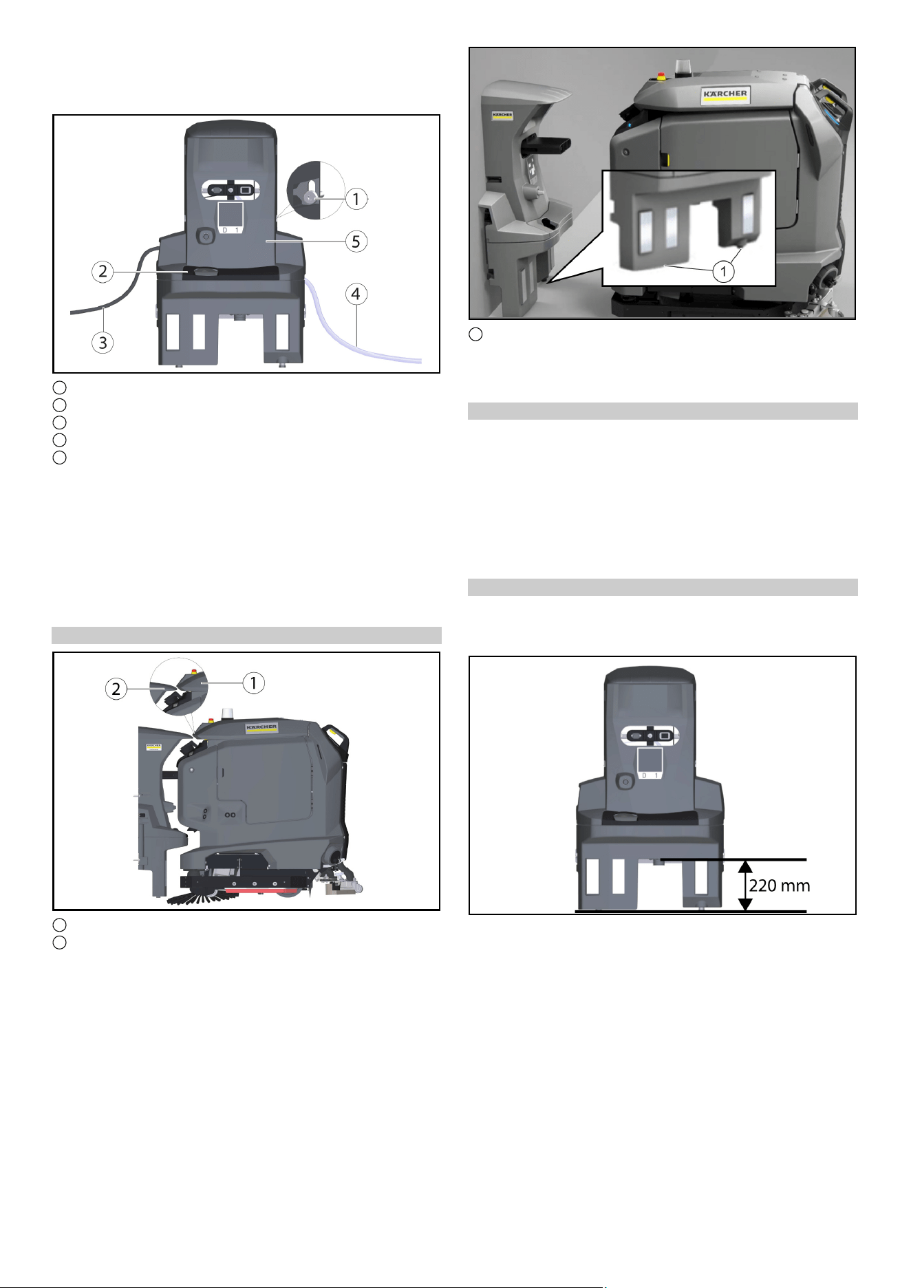
1 Screw
2 Cover
3 Mains cable
4 Hose
5 Docking station upper part
● Tighten the screws on each side.
● Attach the cover.
● Connect the hose to the water supply. Note the maximum per-
missible water pressure in the chapter "Technical data". If nec-
essary, install a pressure reducer in the supply line.
● Plug the mains plug into the socket. The socket must be pro-
tected with a fault current protection switch with a country-spe-
cific permissible tripping current.
● Check the function.
Adjusting the height
1 Waste water tank cap
2 Wedge, docking station
● Move the Device in front of the docking station.
● Check the height alignment: The tip of the wedge on the dock-
ing station must meet the slope on the lid of the dirty water tank
halfway up
●
1 Set screws
● Adjust the height of the docking station with the lower adjust-
ing screws so that the Cliff LiDAR bumper on the Device re-
tracts under the docking station at a distance of approx. 5 mm.
Correct the height
1. Measure the difference dimension to the correct setting di-
mension.
2. Loosen the 4 screws on the docking station and remove them
from the wall.
3. Using the washers, adjust the screw feet on the lower part by
the difference dimension (one washer corresponds to 2 mm).
4. Place the docking station against the wall and fix it with the 4
screws.
5. Recheck the height alignment.
Docking station drain height
Note
Note that the distance between the floor and the height of the
drain of the waste water tank must be 220 mm.
8 English
Free area to be kept around the docking station
Note
In order for the robot to dock reliably at the docking station, suffi-
cient space must be kept free in front of the docking station. The
recommended size of the zone to be kept clear can be found in
the following Illustration.
1 Docking station
2 Area to be kept clear
Installing the water stop valve
To ensure that no water overflows at the docking station, a water
stop valve can also be installed. The water stop valve is mounted
between the tap and the Aquastop hose.
1. Turn off the water supply.
2. Set the arrow to level 8 (40 litre water flow) with the spanner
provided.
Note
The water stop valve can be set from level 1 (5 litre water flow) to
level 10 (50 litre water flow) and closes automatically when more
than the set amount of water has flowed through without interrup-
tion.
3. Attach the upper end of the water stop valve to the tap.
Note
At the entrance of the water stop valve, an upwardly curved Wa-
ter filter is installed. If the Aquastop hose has a Filter mounted, it
must be replaced by a gasket to ensure the function of the Water
Stop Valve.
4. Attach the AquaStop hose to the thread at the bottom of the
water stop valve.
1 Tap
2 Water stop valve
3 Hose
5. Turn the water supply back on.
Resetting the water stop valve
1. Turn off the water supply.
2. Remove the AquaStop hose.
3. Turn off the water stop valve and press in the red pin.
1 Red pin
4. Attach the upper end of the water stop valve to the tap and
press in the red pin.
5. Attach the AquaStop hose to the thread at the bottom of the
water stop valve.
6. Turn the water supply back on
Technical data
Sharp DELTA Q
Device performance data
Number of batteries 2 2
Nominal voltage, Li-Ion V 25,6 25,6
Battery capacity, Li-Ion Ah (5 h) 160 160
Mean power input W 1600 1600
Driving motor power W 2x280 2x280
Suction turbine power W 630 630
Brush drive power W 600 600
Running time with full battery h 3,5 3,5
Protection type IPX3 IPX3
Internal charger
Nominal voltage V 100...240 100...240
Current consumption A <7,5 9,9-4,7
Frequency Hz 50-60 50-60
Power W 760 960
Charging current A 30 40
Français 9
Subject to technical modifications.
Care and service
DANGER
Inadvertently starting up of the unit, touching live compo-
nents
Risk of injury, electric shock
Before doing any work, disconnect the Device from the docking
station or pull the Mains plug.
Cleaning the docking station
몇 WARNING
Danger from electric shock.
Before working on the docking station, unplug the Mains plug
from the power outlet.
1 Waste water collection tray
2 Cover
3 Docking station
4 Position code
5 Male docking port
6 Float switch with float
1. Remove the cover.
2. Check the float switch and float, clean if necessary.
3. Clean the waste water collection tray and rinse it with water.
4. Attach the cover.
5. Den Position code clean with a damp cloth.
6. Check the male docking port for ease of movement.
Note
For suitable use of the docking station, an open space in front of
the docking station 2x2 m
2
to provide for
EU Declaration of Conformity
We hereby declare that the machine described below complies
with the relevant basic safety and health requirements in the EU
Directives, both in its basic design and construction as well as in
the version placed in circulation by us. This declaration is invali-
dated by any changes made to the machine that are not ap-
proved by us.
Product: Kira Docking Station
Type: 2.042-xxx
Currently applicable EU Directives
2006/42/EC (+2009/127/EC)
2014/30/EU
Harmonised standards used
EN 60335-1
EN 60335-2-72
EN IEC 63327
EN IEC 61000-6-2: 2019
EN 61000-6-3: 2007 + A1:2011
National standards used
-
The signatories act on behalf of and with the authority of the com-
pany management.
Documentation supervisor:
S. Reiser
Alfred Kärcher SE & Co. KG
Alfred-Kärcher-Str. 28 - 40
71364 Winnenden (Germany)
Ph.: +49 7195 14-0
Fax: +49 7195 14-2212
Winnenden, 2021/11/01
Remarques générales
Veuillez lire ces instructions de montage avant la
transformation et agissez conformément.
Conservez ces instructions de montage pour une utilisation ulté-
rieure ou pour le propriétaire suivant.
Description
La station d’accueil fournit à l’appareil de l’électricité pour charger
les batteries et de l’eau douce. Après l’accostage, le réservoir
d’eau sale est vidé et rincé. Le réservoir d’eau douce est rempli
et les batteries sont chargées.
Consignes de sécurité
● Respectez les directives locales relatives au traitement et à
l’élimination des eaux usées.
● Le système d’eau est conçu pour une pression maximale de
1 MPa. En cas de dépassement, installez un limiteur de pres-
sion dans la conduite d’alimentation.
● Veillez à ce que le câble secteur n’entre pas en contact avec
les brosses rotatives, les roues ou les roulettes de l’appareil.
Montage
Monter la station d'accueil
Remarque
La station d’accueil est fixée au mur à l’aide de 4 vis. Le diamètre
des vis doit être de 6 mm.
Remarque
Lors de la sélection de l’emplacement de la station d’accueil,
veuillez noter ce qui suit :
●
● La station d’accueil doit être montée à angle droit par rapport
à la surface du sol.
● L’arrière de la station d’accueil doit être contre le mur, l’arrière
ne doit pas être ouvert.
● La station d’accueil doit être installée sur une surface plane.
● La station d’accueil doit être placée sur une surface fermée, si-
non il ne sera pas possible de s’amarrer sans erreur.
● La station d’accueil ne doit pas être installée après une rampe.
Battery charging time h 8 5,25
Waste water pipe
Nominal width of drain mm 50 50
Minimum slope of waste wa-
ter pipe
°1-31-3
Lifting unit requirement
Pumping capacity of the
wastewater lifting station
m
3
/h ≥ 6,5 ≥ 6,5
Dimensions and weights
Weight kg 15,2 15,2
Length x width x height mm 1050x650
x350
1050x650
x350
Sharp DELTA Q
10 Français
● Utiliser le matériel de fixation fourni ou se le procurer en fonc-
tion de la nature du mur.
● Placez la station d’accueil contre le mur et marquez les trous.
1 Tôle de retenue (2x)
2 Vis hexagonale M6x40 (4x)
● Placez la station d’accueil contre le mur et ne vissez que légè-
rement les vis.
● Alignez la station d’accueil et fixez-la au mur.
1 Vidange des eaux sales
2 Station d’accueil pour les pieds
3 Partie inférieure station d'accueil
● À l'aide des rondelles en U fournies (5 par pied à visser),
l’adapter aux conditions du sol.
Remarque
En outre, 4 autres rondelles en U sont fournies.
● Serrer les vis des deux côtés.
● Raccorder l'évacuation des eaux usées au dispositif d'évacua-
tion des eaux usées. Respecter les prescriptions locales en
matière de traitement et d'élimination des eaux usées.
1 Prise du refroidisseur
2 Raccord d'alimentation en eau
● Raccorder le tuyau fourni à l'arrivée d'eau.
Tenir compte du sens du débit (flèche).
● Brancher le câble secteur fourni sur la prise femelle de l'appa-
reil.
1 Vis
2 Cache
3 Câble secteur
4 Flexible
5 Partie supérieure station d'accueil
● Serrer les vis des deux côtés.
● Mettre le cache en place.
● Connectez le tuyau à l’alimentation en eau. Notez la pression
d’eau maximale admissible dans le chapitre
« Caractéristiques techniques ». Si nécessaire, installez un
réducteur de pression dans la conduite d’alimentation.
● Branchez la fiche d’alimentation dans la prise. La prise doit
être fusible avec un disjoncteur à courant résiduel avec un
courant de déclenchement admissible spécifique au pays.
● Contrôler le fonctionnement.
Français 11
Réglage de la hauteur
1 Couvercle du bac d’eau sale
2 Cale, station d'accueil
● Placez l’appareil devant la station d’accueil.
● Vérifiez l’alignement de la hauteur : la pointe de la cale sur la
station d’accueil doit correspondre à la pente sur le couvercle
du réservoir d’eau sale à mi-hauteur
●
1 Vis de réglage
● Ajustez la hauteur de la station d’accueil à l’aide des vis de ré-
glage inférieures de sorte que le pare-chocs Cliff LiDAR de
l’appareil se rétracte sous la station d’accueil à une distance
d’environ 5 mm.
Correction de la hauteur
1. Mesurer la différence par rapport au réglage correct.
2. Desserrez les 4 vis de la station d’accueil et retirez-les du mur.
3. Régler les pieds à visser de la partie inférieure de la différence
à l’aide des rondelles en U (une rondelle en U correspond à
2 mm).
4. Placez la station d’accueil contre le mur et fixez-la à l’aide des
4 vis.
5. Contrôler à nouveau l'alignement en hauteur.
Hauteur de l'évacuation de la station d'accueil
Remarque
Notez que la distance entre le sol et la hauteur de l'évacuation de
la cuve d'eau sale doit être de 220 mm.
Zone libre à garder autour de la station d’accueil
Remarque
Pour que le robot puisse s’amarrer de manière fiable à la station
d’accueil, il faut disposer d’un espace suffisant devant la station
d’accueil. La taille recommandée de la zone à garder dégagée
est indiquée sur la figure suivante.
1 Station d'accueil
2 Espace à garder libre
Installer une vanne d'arrêt d'eau
Pour s’assurer qu’aucun débordement d’eau ne déborde au ni-
veau de la station d’accueil, une vanne d’arrêt d’eau peut égale-
ment être installée. La vanne d’arrêt d’eau est montée entre le
robinet et le tuyau Aquastop.
1. Couper l'alimentation en eau.
2. Placer la flèche sur le niveau 8 (40 litres de débit d'eau) à
l'aide de la clé fournie.
12 Français
Remarque
La vanne d'arrêt d'eau est réglable du niveau 1 (5 litres de débit
d'eau) au niveau 10 (50 litres de débit d'eau) et se ferme automa-
tiquement lorsque la quantité d'eau qui s'est écoulée sans inter-
ruption est supérieure à la quantité réglée.
3. Fixer l'extrémité supérieure de la vanne d'arrêt au robinet
d’eau.
Remarque
À l’entrée de la vanne d’arrêt d’eau, un filtre à eau incurvé vers le
haut est installé. Si le tuyau Aquastop est équipé d’un filtre, celui-
ci doit être remplacé par un joint pour assurer le fonctionnement
de la vanne d’arrêt d’eau.
4. Fixer le flexible d'aquastop au fond fileté de la vanne d'arrêt
d'eau.
1 Robinet d’eau
2 Vanne d'arrêt d'eau
3 Flexible
5. Ouvrir à nouveau l'alimentation en eau.
Réinitialiser la vanne d'arrêt d'eau
1. Couper l'alimentation en eau.
2. Démonter le flexible d'aquastop.
3. Dévisser la vanne d'arrêt d'eau et enfoncer la goupille rouge.
1 Goupille rouge
4. Fixer l'extrémité supérieure de la vanne d'arrêt au robinet
d’eau et enfoncer la goupille rouge.
5. Fixer le flexible d'aquastop au fond fileté de la vanne d'arrêt
d'eau.
6. Ouvrir à nouveau l'alimentation en eau
Caractéristiques techniques
Sous réserve de modifications techniques.
Entretien et maintenance
DANGER
Démarrage intempestif de l'appareil, contact de pièces
conductrices
Risque de blessures, risque d'électrocution
Avant d’effectuer tout travail, débranchez l’appareil de la station
d’accueil ou débranchez-le.
Nettoyer la station d'accueil
몇 AVERTISSEMENT
Danger dû à un choc électrique.
Avant de travailler sur la station d’accueil, débranchez-la de la
prise de courant.
1 Bac à eau sale
2 Cache
3 Station d'accueil
4 Code de position
5 Coulisseau d'accueil
6 Interrupteur à flotteur
Sharp DELTA Q
Caractéristiques de puissance de l’appareil
Nombre de batteries 2 2
Tension nominale, lithium-ion V 25,6 25,6
Capacité de la batterie,
lithium-ion
Ah (5 h) 160 160
Puissance moyenne absor-
bée
W 1600 1600
Puissance du moteur de trac-
tion
W 2x280 2x280
Puissance de la turbine d'as-
piration
W 630 630
Puissance de l'entraînement
de la brosse
W 600 600
Durée de marche avec batte-
rie pleine
h3,53,5
Type de protection IPX3 IPX3
Chargeur interne
Tension nominale V 100...240 100...240
Puissance absorbée A <7,5 9,9-4,7
Fréquence Hz 50-60 50-60
Puissance W 760 960
Courant de charge A 30 40
Durée de charge de la batte-
rie
h 8 5,25
Conduite d’eaux usées
Largeur nominale de l'écoule-
ment
mm 50 50
Pente minimale de la conduite
d'évacuation
°1-31-3
Exigence de l’unité de levage
Capacité de pompage de la
station de relevage des eaux
usées
m
3
/h ≥ 6,5 ≥ 6,5
Dimensions et poids
Poids kg 15,2 15,2
Longueur x largeur x hauteur mm 1050x650
x350
1050x650
x350
Español 13
1. Retirer le cache.
2. Vérifier l'état de l’interrupteur à flotteur en intégralité, le net-
toyer si nécessaire.
3. Nettoyer le bac à eau sale et le rincer à l'eau.
4. Mettre le cache en place.
5. Le Code de position Nettoyez avec un chiffon humide.
6. Vérifier que le coulisseau d'accueil se déplace librement.
Remarque
Pour une utilisation appropriée de la station d’accueil, un espace
ouvert devant la station d’accueil 2x2 m
2
pour prévoir
Déclaration de conformité UE
Nous déclarons par la présente que la machine désignée ci-
après ainsi que la version que nous avons mise en circulation, est
conforme, de par sa conception et son type, aux exigences fon-
damentales de sécurité et de santé en vigueur des normes UE.
Toute modification de la machine sans notre accord annule cette
déclaration.
Produit : Station d'accueil Kira
Type : 2.042-xxx
Normes UE en vigueur
2006/42/CE (+2009/127/CE)
2014/30/UE
Normes harmonisées appliquées
EN 60335-1
EN 60335-2-72
EN IEC 63327
EN IEC 61000-6-2: 2019
EN 61000-6-3: 2007 + A1:2011
Normes nationales appliquées
-
Les signataires agissent sous ordre et avec le pouvoir de la direc-
tion.
Responsable de la documentation :
S. Reiser
Alfred Kärcher SE & Co. KG
Alfred-Kärcher-Str. 28 - 40
71364 Winnenden (Germany)
Tél. : +49 7195 14-0
Télécopie : +49 7195 14-2212
Winnenden, le 01/11/2021
Avisos generales
Lea estas instrucciones de montaje antes del mismo
y sígalas.
Conserve las instrucciones de montaje para su uso posterior o
para futuros propietarios.
Descripción
La estación de acoplamiento suministra al dispositivo electrici-
dad para cargar las baterías y agua dulce. Después del acopla-
miento, el tanque de agua sucia se vacía y se enjuaga. Se rellena
el depósito de agua dulce y se cargan las baterías.
Instrucciones de seguridad
● Deben tenerse en cuenta las normativas locales en materia de
tratamiento y eliminación de aguas residuales.
● El sistema de alimentación de agua está diseñado para un
máximo de 1 MPa. Instalar un limitador de presión en la fuente
de alimentación si se supera la presión.
● Asegurarse de que el cable de alimentación no entre en con-
tacto con los cepillos, ruedas o rodillos giratorios del equipo.
Montaje
Montaje de la estación de acoplamiento
Nota
La estación de acoplamiento se fija a la pared con 4 tornillos. El
diámetro de los tornillos debe ser de 6 mm.
Nota
Al seleccionar la ubicación de la estación de acoplamiento, tenga
en cuenta lo siguiente:
●
● La estación de acoplamiento debe montarse en ángulo recto
con respecto a la superficie del suelo.
● La parte posterior de la estación de acoplamiento debe estar
contra la pared, la parte posterior no debe estar abierta.
● La estación de acoplamiento debe instalarse sobre una super-
ficie plana.
● La estación de acoplamiento debe colocarse sobre una super-
ficie cerrada, de lo contrario no será posible acoplar sin erro-
res.
● La estación de acoplamiento no debe instalarse después de
una rampa.
● Utilizar el material de fijación suministrado o comprarlo en fun-
ción de la naturaleza de la pared.
● Coloque la estación de acoplamiento contra la pared y mar-
que los agujeros.
14 Español
1 Chapa de sujeción (2 uds.)
2 Tornillo hexagonal M6 x 40 (4 uds.)
● Coloque la estación de acoplamiento contra la pared y atorni-
lle los tornillos solo ligeramente.
● Alinee la estación de acoplamiento y fíjela a la pared.
1 Purgado de agua sucia
2 Estación de acoplamiento a pie
3 Parte inferior de la estación de acoplamiento
● Ajustar a las condiciones del terreno con la ayuda de las aran-
delas suministradas (5 uds. por pata roscada).
Nota
Además, se adjuntan 4 arandelas más.
● Fijar los tornillos de ambos lados.
● Conectar el purgado para agua sucia al lugar de eliminación
de aguas residuales. Tener en cuenta la normativa local en re-
lación con el tratamiento y la eliminación de las aguas residua-
les.
1 Enchufe de dispositivo frío
2 Conexión de agua
● Conectar la manguera suministrada a la conexión de agua.
Tener en cuenta la dirección de circulación (flecha).
● Conectar el cable de red suministrado al enchufe de dispositi-
vo frío del equipo.
1 Tornillo
2 Cubierta
3 Cable de red
4 Manguera
5 Parte superior de la estación de acoplamiento
● Fijar los tornillos de ambos lados.
● Colocar la cubierta.
● Conecte la manguera al suministro de agua. Tenga en cuenta
la presión máxima de agua permitida en el capítulo "Datos téc-
nicos". Si es necesario, instale un reductor de presión en la lí-
nea de suministro.
● Enchufe el enchufe de alimentación en la toma de corriente.
El enchufe debe estar fusionado con un disyuntor de corriente
residual con una corriente de disparo permitida específica del
país.
● Comprobar el funcionamiento.
Ajuste de la altura
1 Tapa del depósito de agua sucia
2 Calza, estación de acoplamiento
● Mueva el dispositivo frente a la estación de acoplamiento.
● Compruebe la alineación de la altura: La punta de la cuña de
la estación de acoplamiento debe coincidir con la pendiente
de la tapa del depósito de agua sucia a mitad de camino
Español 15
●
1 Tornillos de fijación
● Ajuste la altura de la estación de acoplamiento con los torni-
llos de ajuste inferiores para que el parachoques Cliff LiDAR
del dispositivo se retraiga debajo de la estación de acopla-
miento a una distancia de aprox. 5 mm.
Corrección de la altura
1. Medir la diferencia con respecto al ajuste correcto.
2. Afloje los 4 tornillos de la estación de acoplamiento y retírelos
de la pared.
3. Ajustar las patas roscadas en la parte inferior por la diferencia
utilizando las arandelas (una arandela corresponde a 2 mm).
4. Coloque la estación de acoplamiento contra la pared y fíjela
con los 4 tornillos.
5. Comprobar de nuevo la alineación de altura.
Altura del desagüe de la estación de acoplamiento
Nota
Tenga en cuenta que la distancia entre el suelo y la altura del
desagüe de la bandeja de aguas residuales debe ser de 220 mm.
Área libre para mantener alrededor de la estación de
acoplamiento
Nota
Para que el robot pueda acoplarse de forma fiable a la estación
de acoplamiento, se debe mantener suficiente espacio libre de-
lante de la estación de acoplamiento. El tamaño recomendado
de la zona a mantener despejada se puede ver en la siguiente
figura.
1 Estación de acoplamiento
2 Superficie que debe mantenerse libre
Montaje de la válvula de cierre de agua
Para garantizar que no se desborde agua en la estación de aco-
plamiento, también se puede instalar una válvula de cierre de
agua. La válvula de cierre de agua está montada entre el grifo y
la manguera Aquastop.
1. Cerrar la entrada de agua.
2. Colocar la flecha en el nivel 8 (caudal de agua de 40 litros) con
la llave suministrada.
Nota
La válvula de cierre de agua es ajustable desde el nivel 1 (caudal
de agua de 5 litros) hasta el nivel 10 (caudal de agua de 50 litros)
y se cierra automáticamente cuando ha pasado más de la canti-
dad de agua establecida sin interrupción.
3. Conectar el extremo superior de la válvula de cierre de agua
al grifo de agua.
Nota
En la entrada de la válvula de cierre de agua, se instala un filtro
de agua curvado hacia arriba. Si la manguera Aquastop tiene un
filtro montado, debe reemplazarse por un sello para garantizar el
funcionamiento de la válvula de cierre de agua.
4. Fijar la manguera Aquastop a la parte inferior roscada de la
válvula de cierre de agua.
16 Español
1 Grifo de agua
2 Válvula de cierre de agua
3 Manguera
5. Volver a abrir la entrada de agua.
Reajuste de la válvula de cierre de agua
1. Cerrar la entrada de agua.
2. Desmontar la manguera Aquastop.
3. Cerrar la válvula de cierre de agua y presionar el pasador rojo.
1 Pasador rojo
4. Fijar el extremo superior de la válvula de cierre de agua al grifo
de agua y presionar el pasador rojo.
5. Fijar la manguera Aquastop a la parte inferior roscada de la
válvula de cierre de agua.
6. Volver a abrir la entrada de agua
Datos técnicos
Nos reservamos el derecho a realizar modificaciones.
Conservación y mantenimiento
PELIGRO
Equipo que arranca involuntariamente, contacto con piezas
que conducen corriente
Riesgo de lesiones, descarga eléctrica
Antes de realizar cualquier trabajo, desconecte el dispositivo de
la estación de acoplamiento o desconéctelo.
Limpieza de la estación de acoplamiento
몇 ADVERTENCIA
Peligro por descarga eléctrica.
Antes de trabajar en la estación de acoplamiento, desconéctela
de la toma de corriente.
1 Bandeja de agua sucia
2 Cubierta
3 Estación de acoplamiento
4 Código de posición
5 Vástago de acoplamiento
6 Interruptor flotador con flotador
1. Retirar la cubierta.
2. Comprobar el interruptor flotador y el flotador, y limpiarlos si
es necesario.
3. Limpiar la bandeja de agua sucia y enjuagarla con agua.
4. Colocar la cubierta.
5. El Código de posición Limpiar con un paño húmedo.
6. Comprobar que el vástago de acoplamiento se mueve libre-
mente.
Nota
Para un uso adecuado de la estación de acoplamiento, un espa-
cio abierto frente a la estación de acoplamiento de 2x2 m
2
para
proveer a
Declaración de conformidad UE
Por la presente declaramos que la máquina designada a conti-
nuación cumple, en lo que respecta a su diseño y tipo construc-
tivo así como a la versión puesta a la venta por nosotros, las
normas básicas de seguridad y sobre la salud que figuran en las
directivas comunitarias correspondientes. Si se producen modifi-
caciones no acordadas en la máquina, esta declaración pierde
su validez.
Producto: Estación de acoplamiento Kira
Tipo: 2.042-xxx
Directivas UE aplicables
2006/42/CE (+2009/127/CE)
2014/30/UE
Sharp DELTA Q
Datos de potencia del equipo
Número de baterías 2 2
Tensión nominal, iones de li-
tio
V 25,6 25,6
Capacidad de las baterías, io-
nes de litio
Ah (5 h) 160 160
Consumo medio de energía W 1600 1600
Potencia del motor W 2x280 2x280
Potencia de la turbina de as-
piración
W 630 630
Potencia del accionamiento
de cepillos
W 600 600
Tiempo de marcha con la ba-
tería llena
h3,53,5
Tipo de protección IPX3 IPX3
Cargador interno
Tensión nominal V 100...240 100...240
Consumo de corriente A <7,5 9,9-4,7
Frecuencia Hz 50-60 50-60
Potencia W 760 960
Corriente de carga A 30 40
Tiempo de carga de la batería h 8 5,25
Conducto de agua residual
Ancho nominal drenaje mm 50 50
Pendiente mínima del con-
ducto de agua residual
°1-31-3
Requisito de la unidad de elevación
Capacidad de bombeo de la
estación elevadora de aguas
residuales
m
3
/h ≥ 6,5 ≥ 6,5
Peso y dimensiones
Peso kg 15,2 15,2
Longitud x anchura x altura mm 1050x650
x350
1050x650
x350
Sharp DELTA Q
Nederlands 17
Normas armonizadas aplicadas
EN 60335-1
EN 60335-2-72
EN IEC 63327
EN IEC 61000-6-2: 2019
EN 61000-6-3: 2007 + A1:2011
Normas nacionales aplicadas
-
Los abajo firmantes actúan en nombre y con la autorización de la
junta directiva.
Responsable de documentación:
S. Reiser
Alfred Kärcher SE & Co. KG
Alfred-Kärcher-Str. 28 - 40
71364 Winnenden (Germany)
Tel.: +49 7195 14-0
Fax: +49 7195 14-2212
Winnenden, 01/11/2021
Algemene instructies
Lees deze montagehandleiding vóór de ombouw en
handel dienovereenkomstig.
Bewaar de montagehandleiding voor later gebruik of voor de vol-
gende eigenaar.
Beschrijving
Het docking station voorziet het apparaat van elektriciteit om de
accu's en vers water op te laden. Na het aanmeren wordt de vuil-
watertank geleegd en doorgespoeld. De schoonwatertank wordt
bijgevuld en de accu's worden opgeladen.
Veiligheidsinstructies
● Neem de plaatselijke voorschriften voor behandeling en af-
voer van afvalwater in acht.
● Het watersysteem is ontworpen voor maximaal 1 MPa. Instal-
leer een drukbegrenzer in de toevoerleiding als deze waarde
wordt overschreden.
● Zorg ervoor dat het netsnoer niet in contact komt met de draai-
ende borstels, wielen of rollen van het apparaat.
Montage
Het dockingstation installeren
Instructie
Het dockingstation wordt met 4 schroeven aan de muur beves-
tigd. De diameter van de schroeven moet 6 mm zijn.
Instructie
Houd bij het kiezen van de locatie voor het dockingstation reke-
ning met het volgende:
●
● Het dockingstation moet haaks op het vloeroppervlak worden
gemonteerd.
● De achterkant van het dockingstation moet tegen de muur lig-
gen, de achterkant mag niet open zijn.
● Het dockingstation moet op een vlakke ondergrond worden
opgesteld.
● Het dockingstation moet op een gesloten oppervlak worden
geplaatst, anders is het niet mogelijk om foutloos te docken.
● Het dockingstation mag niet na een helling worden opgesteld.
● Gebruik het meegeleverde bevestigingsmateriaal, of koop het
afhankelijk van de aard van de muur.
● Plaats het dockingstation tegen de muur en markeer gaten.
1 Bevestigingsplaat (2x)
2 6kt Schroef M6x40 (4x)
● Plaats het dockingstation tegen de muur en draai de schroe-
ven slechts lichtjes vast.
● Lijn het dockingstation uit en bevestig het aan de muur.
18 Nederlands
1 Vuil water afvoeren
2 Voet Docking Station
3 Dockingstation voor het onderste deel
● Met behulp van meegeleverde U-ringen (5 stuks per schroef-
basis) aanpassen aan de bodemgesteldheid.
Instructie
Daarnaast worden er nog 4 U-ringen meegeleverd.
● Draai de schroeven aan beide zijden vast.
● Sluit de afvoer voor vuil water aan op de afvoer van afvalwa-
ter. Neem de plaatselijke voorschriften voor de behandeling
en afvoer van afvalwater in acht.
1 IEC-aansluiting
2 Watervoorziening
● Sluit de meegeleverde slang aan op de wateraansluiting.
Let op de stroomrichting (pijl).
● Sluit het meegeleverde netsnoer aan op het stopcontact van
het apparaat.
1 Schroef
2 Bedekken
3 Stroomkabel
4 Slang
5 Dockingstation aan de bovenkant
● Draai de schroeven aan beide zijden vast.
● Bevestig het deksel.
● Sluit de slang aan op de watertoevoer. Let op de maximaal
toelaatbare waterdruk in het hoofdstuk "Technische gege-
vens". Installeer indien nodig een drukregelaar in de toevoer-
leiding.
● Steek de stekker in het stopcontact. Het stopcontact moet
worden afgezekerd met een aardlekschakelaar met een land-
specifieke toegestane uitschakelstroom.
● Controleer op functie.
Hoogte aanpassen
1 Deksel vuilwatertank
2 Wig, dockingstation
● Verplaats het apparaat voor het dockingstation.
● Controleer de hoogte-uitlijning: De punt van de wig op het doc-
kingstation moet halverwege de helling op het deksel van de
vuilwatertank raken
●
1 Set schroeven
● Stel de hoogte van het dockingstation in met de onderste stel-
schroeven zodat de Cliff LiDAR-bumper op het apparaat op
een afstand van ca. 5 mm onder het dockingstation intrekt.
Hoogte corrigeren
1. Meet het verschil naar de juiste instelling.
2. Draai de 4 schroeven op het dockingstation los en verwijder ze
van de muur.
3. Stel de schroefvoeten op het onderste deel af door het verschil
met behulp van de U-ringen (één U-ring komt overeen met 2
mm).
Nederlands 19
4. Plaats het docking station tegen de muur en zet het vast met
de 4 schroeven.
5. Controleer de uitlijning van de hoogte opnieuw.
Hoogte van het dockingstation voor afvoeren
Instructie
Houd er rekening mee dat de afstand tussen de vloer en de hoog-
te van de afvoer van de vuilwatertank 220 mm moet zijn.
Vrije ruimte die rond het dockingstation moet worden
gehouden
Instructie
Om ervoor te zorgen dat de robot betrouwbaar aan het doc-
kingstation dockt, moet er voldoende ruimte vrij worden gehou-
den voor het dockingstation. De aanbevolen grootte van de zone
die vrij moet worden gehouden, is te zien in de volgende afbeel-
ding.
1 Basisstation
2 Vrij te houden ruimte
De waterstopklep installeren
Om ervoor te zorgen dat er geen water overloopt bij het doc-
kingstation, kan ook een waterstopklep worden geïnstalleerd. De
waterstopklep wordt tussen de kraan en de Aquastop-slang ge-
monteerd.
1. Sluit de watertoevoer af.
2. Zet de pijl op niveau 8 (40 liter waterstroom) met de meegele-
verde sleutel.
Instructie
De waterstopklep is instelbaar van niveau 1 (5 liter waterstroom)
tot niveau 10 (50 liter waterstroom) en sluit automatisch wanneer
er zonder onderbreking meer dan de ingestelde hoeveelheid wa-
ter is doorgestroomd.
3. Bevestig het bovenste uiteinde van de waterstopklep aan de
kraan.
Instructie
Bij de ingang van de waterstopklep is een naar boven gebogen
waterfilter geïnstalleerd. Als er een filter op de Aquastop-slang is
gemonteerd, moet deze worden vervangen door een afdichting
om de werking van de waterstopklep te garanderen.
4. Bevestig de Aquastop-slang aan de schroefdraadbodem van
de waterstopklep.
1 Kraan
2 De klep van de waterstop
3 Slang
5. Draai de watertoevoer weer open.
Reset de waterstopklep
1. Sluit de watertoevoer af.
2. Demonteer de Aquastop-slang.
3. Draai de waterstopklep dicht en druk de rode pin in.
1 Rode pen
4. Bevestig het bovenste uiteinde van de waterstopklep aan de
kraan en druk de rode pen erin.
5. Bevestig de Aquastop-slang aan de schroefdraadbodem van
de waterstopklep.
6. Zet de watertoevoer weer aan
20 Italiano
Technische gegevens
Technische wijzigingen voorbehouden.
Verzorging en onderhoud
GEVAAR
Onbedoeld startend apparaat, contact met onder spanning
staande delen
Gevaar voor letsel, elektrische schok
Voordat u werkzaamheden uitvoert, koppelt u het apparaat los
van het dockingstation of haalt u de stekker uit het stopcontact.
Dockingstation reinigen
몇 WAARSCHUWING
Gevaar voor elektrische schokken.
Voordat u aan het dockingstation gaat werken, haalt u de stekker
uit het stopcontact.
1 Bak voor vuil water
2 Bedekken
3 Basisstation
4 Positiecode
5 Docking plunjer
6 Vlotterschakelaar met vlotter
1. Verwijder het deksel.
2. Controleer de vlotterschakelaar en vlotter, reinig indien nodig.
3. Reinig de vuilwaterbak en spoel af met water.
4. Bevestig het deksel.
5. De Positiecode Reinig met adamp kleding.
6. Controleer of de dockingzuiger vrij kan bewegen.
Instructie
Voor een geschikt gebruik van het dockingstation is een open
ruimte voor het dockingstation 2x2 m
2
om te voorzien in
EU-conformiteitsverklaring
Hiermee verklaren wij dat de hierna vermelde machine op basis
van het ontwerp en type en in de door ons op de markt gebrachte
uitvoering voldoet aan de relevante veiligheids- en gezondheids-
vereisten van de EU-richtlijnen. Bij een niet door ons goedge-
keurde wijziging van de machine verliest deze verklaring zijn
geldigheid.
Product: Kira dockingstation
Type: 2.042-xxx
Relevante EU-richtlijnen
2006/42/EG (+2009/127/EG)
2014/30/EU
Toegepaste geharmoniseerde normen
EN 60335-1
EN 60335-2-72
EN IEC 63327
EN IEC 61000-6-2: 2019
EN 61000-6-3: 2007 + A1:2011
Toegepaste nationale normen
-
De ondergetekenden handelen in opdracht en met volmacht van
de directie.
Gevolmachtigde voor de documentatie:
S. Reiser
Alfred Kärcher SE & Co. KG
Alfred-Kärcher-Str. 28 - 40
71364 Winnenden (Germany)
Tel.: +49 7195 14-0
Fax: +49 7195 14-2212
Winnenden, 2021/11/01
Avvertenze generali
Leggere queste istruzioni di montaggio prima della
conversione e agire di conseguenza.
Conservare le istruzioni di montaggio per un uso futuro o per un
successivo proprietario.
Descrizione
La stazione di docking fornisce all'apparecchio elettricità per ca-
ricare le batterie e acqua pulita. Dopo il docking, il serbatoio per
l'acqua sporca viene svuotato e risciacquato. Il serbatoio acqua
pulita viene riempito e le batterie vengono caricate.
Avvertenze di sicurezza
● Attenersi alle prescrizioni locali sul trattamento e lo smaltimen-
to delle acque di scarico.
● Il sistema idrico è progettato per un massimo di 1 MPa. Instal-
lare un limitatore di pressione nella linea di alimentazione se
la pressione viene superata.
● Assicurarsi che il cavo di alimentazione non entri in contatto
con le spazzole rotanti, le ruote o i rulli dell'apparecchio.
Montaggio
Montare la docking station
Nota
La docking station è fissata al muro con 4 viti. Il diametro delle viti
deve essere di 6 mm.
Nota
Si prega di tenere presente quanto segue nella scelta della posi-
zione per la stazione di docking:
Sharp DELTA Q
Gegevens capaciteit apparaat
Aantal batterijen 2 2
Nominale spanning, li-ion V 25,6 25,6
Batterijcapaciteit, li-ion Ah (5 h) 160 160
Gemiddelde netbelasting W 1600 1600
Vermogen rijmotor W 2x280 2x280
Vermogen zuigturbine W 630 630
Vermogen borstelaandrijving W 600 600
Looptijd met volle batterij h 3,5 3,5
Beschermingsgraad IPX3 IPX3
Interne oplader
Nominale spanning V 100...240 100...240
Stroomopname A <7,5 9,9-4,7
Frequentie Hz 50-60 50-60
Vermogen W 760 960
Laadstroom A 30 40
Oplaadduur batterij h 8 5,25
Afvoerwaterleiding
Nominale wijdte afvoer mm 50 50
Minimale helling afvoerleiding ° 1-3 1-3
Vereiste hefunit
Afvoerpomp voor vuilwater m
3
/h ≥ 6,5 ≥ 6,5
Afmetingen en gewichten
Gewicht kg 15,2 15,2
Lengte x breedte x hoogte mm 1050x650
x350
1050x650
x350
Italiano 21
●
● La docking station deve essere montata ad angolo retto rispet-
to alla superficie del pavimento.
● Il retro della docking station deve essere a contatto con il mu-
ro, il retro non deve essere aperto.
● La costruzione della stazione di docking dovrebbe avvenire su
una superficie piana.
● La docking station dovrebbe trovarsi su una superficie chiusa,
altrimenti non è possibile un accoppiamento senza errori.
● La stazione di docking non deve essere costruita su una ram-
pa.
● Utilizzare il materiale di fissaggio allegato, oppure procurarsi
in base alla natura del muro.
● Posizionare la docking station contro il muro e segnare i fori.
1 Piastra di supporto (2x)
2 6kt-vite M6x40 (4x)
● Posizionare la docking station contro il muro e avvitare le viti
solo leggermente.
● Allineare la docking station e fissarla al muro.
1 Acqua di scarico
2 Docking station per piedi
3 Sottoparte della docking station
● Con l'aiuto delle rondelle a U fornite (5 pezzi per piede di vite),
adattarsi alle condizioni del suolo.
Nota
In aggiunta, vengono fornite altre 4 rondelle a U.
● Stringere le viti su entrambi i lati.
● Collegare il permesso per le acque reflue con l'impianto di
smaltimento delle acque reflue. Osservare le normative locali
sul trattamento e smaltimento delle acque reflue.
1 presa per apparecchi a freddo
2 Collegamento dell'acqua
● Collegare il tubo allegato all'attacco dell'acqua.
Prestare attenzione alla direzione del flusso (freccia).
● Collegare il cavo di alimentazione incluso alla presa per appa-
recchi a freddo sul dispositivo.
22 Italiano
1 Vite
2 Copertura
3 Cavo di rete
4 tubo
5 Stazione di docking superiore
● Stringere le viti su entrambi i lati.
● Installare la copertura.
● Collegare il tubo all'approvvigionamento idrico. Prestare atten-
zione alla pressione massima dell'acqua consentita nel capi-
tolo "Dati tecnici". Se necessario, installare un riduttore di
pressione nella conduttura.
● Inserire la spina nella presa. La presa deve essere protetta da
un interruttore per dispersione di corrente con una corrente di
attivazione consentita specifica per il paese.
● Controllare la funzione.
Regolare l'altezza
1 Coperchio serbatoio per l'acqua sporca
2 Keil, stazione di docking
● Portare l'apparecchio davanti alla docking station.
● Controllare l'allineamento in altezza: La punta del cuneo alla
stazione di docking deve incontrare l'inclinazione sul coper-
chio del serbatoio delle acque reflue a metà altezza.
●
1 Viti di regolazione
● Regolare la docking station con le viti di regolazione inferiori in
modo che il paraurti Cliff LiDAR entri nell'apparecchio con un
distacco di circa 5 mm sotto la docking station.
Correggere l'altezza
1. Misurare la differenza rispetto all'impostazione corretta.
2. Allentare le 4 viti della docking station e rimuoverla dal muro.
3. Regolare i piedini sul fondo per compensare la differenza con
l'aiuto delle rondelle a U (una rondella a U corrisponde a 2
mm).
4. Posizionare la docking station contro il muro e fissarla con le
4 viti.
5. Controllare nuovamente l'allineamento in altezza.
Altezza di scarico della stazione di docking
Nota
Si prega di notare che la distanza tra il pavimento e l'altezza dello
scarico della vasca di acque reflue deve essere di 220 mm.
Area da tenere libera intorno alla stazione di attracco
Nota
Affinché il robot possa agganciarsi in modo affidabile alla stazio-
ne di docking, è necessario mantenere uno spazio sufficiente da-
vanti alla stazione di docking. La dimensione raccomandata della
zona da mantenere libera può essere estratta dalla seguente fi-
gura.
1 Stazione di docking
2 Area da mantenere libera
Italiano 23
Installare la valvola di arresto dell'acqua
Per garantire che non ci sia fuoriuscita d'acqua dalla stazione di
docking, è possibile installare una valvola di arresto dell'acqua.
La valvola di arresto dell'acqua viene montata tra il rubinetto e il
tubo Aquastopp.
1. Interrompere l'approvvigionamento idrico.
2. Regolare la freccia con la chiave fornita su livello 8 (40 litri di
flusso d'acqua).
Nota
La valvola di arresto dell'acqua è regolabile da livello 1 (5 litri di
flusso d'acqua) a livello 10 (50 litri di flusso d'acqua) e si chiude
automaticamente quando più della quantità d'acqua impostata è
passata senza interruzione.
3. Fissare l'estremità superiore della valvola di arresto dell'acqua
al rubinetto.
Nota
All'ingresso della valvola di arresto dell'acqua è installato un filtro
per l'acqua curvato verso l'alto. Se il tubo Aquastopp ha un filtro
montato, questo deve essere sostituito con una guarnizione affin-
ché la funzione della valvola di arresto dell'acqua possa essere
garantita.
4. Fissare il tubo Aquastopp alla base filettata della valvola di ar-
resto dell'acqua.
1 Rubinetto
2 valvola di arresto dell'acqua
3 tubo
5. Riaccendere l'approvvigionamento idrico.
Ripristinare la valvola di arresto dell'acqua
1. Interrompere l'approvvigionamento idrico.
2. Smontare il tubo Aquastopp.
3. Chiudere la valvola di arresto dell'acqua e premere il perno
rosso.
1 Pennarello rosso
4. Fissare l'estremità superiore della valvola di arresto dell'acqua
al rubinetto e premere il perno rosso.
5. Fissare il tubo Aquastopp alla base filettata della valvola di ar-
resto dell'acqua.
6. Riavvitare l'approvvigionamento idrico
Dati tecnici
Con riserva di modifiche tecniche.
Cura e manutenzione
PERICOLO
Dispositivo che si avvia involontariamente, contatto con
parti sotto tensione
Pericolo di infortunio, scossa elettrica
Disconnettere l'apparecchio dalla docking station o staccare la
spina prima di qualsiasi lavoro.
Pulire la docking station
몇 AVVERTIMENTO
Pericolo di scossa elettrica.
Prima di lavorare sulla docking station, estrarre la spina dalla pre-
sa.
1 Vasca per acque reflue
2 Copertura
3 Stazione di docking
4 Codice posizione
5 Puntale di attracco
6 interruttore a galleggiante con galleggiante
Sharp DELTA Q
Dati sulle prestazioni dell’apparecchio
Numero di batterie 2 2
Tensione nominale, Li-Ion V 25,6 25,6
Capacità della batteria, Li-Ion Ah (5 h) 160 160
Assorbimento di potenza me-
dio
W 1600 1600
Potenza motore di trazione W 2x280 2x280
Potenza turbina di aspirazio-
ne
W 630 630
Potenza motore delle spazzo-
le
W 600 600
Tempo di funzionamento con
batteria carica
h3,53,5
Grado di protezione IPX3 IPX3
Caricabatterie interno
Tensione nominale V 100...240 100...240
Corrente assorbita A <7,5 9,9-4,7
Frequenza Hz 50-60 50-60
Potenza W 760 960
Corrente di carica A 30 40
Tempo di ricarica della batte-
ria
h 8 5,25
Tubo dell’acqua di scarico
Diametro nominale dello sca-
rico
mm 50 50
Pendenza minima della tuba-
zione di scarico
°1-31-3
Richiesta unità di sollevamento
Pompa di sollevamento ac-
que reflue
m
3
/h ≥ 6,5 ≥ 6,5
Dimensioni e pesi
Peso kg 15,2 15,2
Lunghezza x larghezza x al-
tezza
mm 1050x650
x350
1050x650
x350
24 Русский
1. Rimuovere la copertura.
2. Controllare l'interruttore a galleggiante e il galleggiante, pulire
se necessario.
3. Pulire la vasca delle acque reflue e sciacquarla con acqua.
4. Installare la copertura.
5. IlCodice posizionepulire con un panno umido.
6. Controllare la libertà di movimento del pistone di docking.
Nota
Per un utilizzo adeguato della docking station è necessaria
un'area libera di 2x2 m davanti alla docking station.
2
prevedere
Dichiarazione di conformità UE
Con la presente dichiariamo che la macchina di seguito definita,
in conseguenza della sua progettazione e costruzione nonché
nello stato in cui è stata immessa sul mercato, è conforme ai re-
quisiti essenziali di sicurezza e salute pertinenti delle direttive
UE. In caso di modifiche apportate alla macchina senza il nostro
consenso, la presente dichiarazione perde ogni validità.
Prodotto: Docking Station Kira
Tipo: 2.042-xxx
Direttive UE pertinenti
2006/42/CE (+2009/127/EG)
2014/30/UE
Norme armonizzate applicate
EN 60335-1
EN 60335-2-72
EN IEC 63327
EN IEC 61000-6-2: 2019
EN 61000-6-3: 2007 + A1:2011
Norme nazionali applicate
-
I firmatari agiscono per incarico e con delega della direzione.
Responsabile della documentazione:
S. Reiser
Alfred Kärcher SE & Co. KG
Alfred-Kärcher-Str. 28 - 40
71364 Winnenden (Germany)
Tel.: +49 7195 14-0
Fax: +49 7195 14-2212
Winnenden, 01/11/2021
Общие указания
Перед переоборудованием следует
ознакомиться с настоящей инструкцией по
монтажу и действовать в соответствии с ней.
Сохранить инструкцию по монтажу для дальнейшего
пользования или для следующего владельца.
Описание
Док-станция снабжает аппарат, устройство, прибор, машина
электричеством для зарядки аккумуляторов и пресной
водой. После стыковки бак для грязной воды опорожняется и
промывается. бак для чистой воды, резервуар для чистой
воды наполняется и аккумуляторы заряжаются.
Указания по технике безопасности
● Соблюдайте местные правила очистки и утилизации
сточных вод.
●Система водоснабжения рассчитана на максимальное
давление 1 МПа. При превышении давления в линии
подачи установите ограничитель давления.
●Следите за тем, чтобы сетевой кабель не соприкасался с
вращающимися щетками, колесами или роликами
устройства.
Сборка
Установите док-станцию
Примечание
Док-станция крепится к стене 4 винтами. Диаметр
саморезов должен быть 6 мм.
Примечание
При выборе места для док-станции обратите внимание на
следующее:
●
●Док-станцию необходимо монтировать под прямым углом
к поверхности пола.
●Задняя часть док-станции должна опираться на стену и не
должна быть открыта.
●Док-станцию следует устанавливать на ровной
поверхности.
●Док-станция должна располагаться в закрытом
помещении, иначе безошибочная стыковка невозможна.
●Док-станцию нельзя устанавливать на пандусе.
● Использовать прилагаемый крепежный материал или
пр
иобрести его в зави
симости от качества стены.
● Поместите док-станцию на стену и отметьте отверстия.
Русский 25
1 Крепежная пластина (2 шт.)
2 Винт с шестигранной головкой M6x40 (4 шт.)
● Поместите док-станцию на стену и слегка вверните винты.
●Выровняйте док-станцию и прикрепите ее к стене.
1 Слив грязной воды
2 Док-станция для ног
3 Нижняя часть док-станции
● Отрегулировать в соответствии с уровнем пола с
помощью прилагаемых шайб (5 на винтовую ножку).
Примечание
Дополнительно прилагаются еще 4 шайбы.
● Затянуть винты с обеих сторон.
● Соединить слив для грязной воды с канализацией.
Соблюдать местные правила очистки и утилизации
сточных вод.
1 Гнездо
2 Патрубок для подвода воды
● Подсоединить шланг, входящий в комплект поставки, к
патрубку для подвода воды.
Соблюдать направление потока (стрелка).
● Подсоединить сетевой кабель, входящий в комплект
поставки, к гнезду на устройстве.
1 Винт
2 Крышка
3 Сетевой кабель
4 Шланг
5 Верхняя часть док-станции
●Затянуть винты с обеих сторон.
● Установить крышку.
● Подсоедините шланг к водопроводу. Соблюдайте
максимально допустимое давление воды, указанное в
главе «Технические данные». При необходимости
установите на подающую линию редуктор давления.
● Вставьте сетевая вилка в розетку. Розетка должна быть
защищена автомат защитного отключения с допустимым
током срабатывания в зависимости от ст
раны.
●Проверить функционирование.
Регулировка высоты
1 Крышка бака для грязной воды
2 Клин, док-станция
● Переместите аппарат, устройство, прибор, машина перед
док-станцией.
●Проверьте выравнивание по высоте: кончик клина на док-
станции должен совпадать с наклоном крышки
резервуара для грязной воды наполовину вверх.
26 Русский
●
1 регулировочные винты
● Отрегулируйте высоту док-станции с помощью нижних
регулировочных винтов так, чтобы защита от ударов Cliff
LiDAR на аппарат, устройство, прибор, машина
втягивалась примерно на 5 мм ниже док-станции.
Корректировка высоты
1. Измерить разницу до правильной настройки.
2. Ослабьте 4 винта на док-станции и снимите ее со стены.
3. Отрегулировать винтовые ножки на нижней части на
разницу с помощью шайб (одна шайба соответствует
2 мм).
4. Поместите док-станцию на стену и закрепите ее 4
винтами.
5. Снова проверить выравнивание по высоте.
Высота слива док-станции
Примечание
Обратить внимание, что расстояние между полом и
высотой слива поддона для грязной воды должно
составлять 220 мм.
Вокруг док-станции должно быть свободное
пространство.
Примечание
Чтобы робот мог надежно пристыковаться к док-
станции, перед док-станцией должно быть оставлено
достаточно свободного места. Рекомендуемый размер
зоны, которую следует сохранять свободной, можно
увидеть на следующем рисунок .
1 Док-станция
2 Площадь, которую нужно оставлять свободной
Установка водозапорного клапана
Чтобы гарантировать отсутствие перелива воды на док-
станции, можно также установить водяной запорный клапан.
Водозапорный клапан устанавливается между краном и
шлангом Аквастоп.
1. Перекрыть подачу воды.
2. Установить стрелку на уровень 8 (расход воды 40 литров)
с помощью гаечного ключа, входящего в комплект
поставки.
Примечание
Водозапорный клапан регулируется от уровня 1 (расход
воды 5 литров) до уровня 10 (расход воды 50 литров) и
автоматически закрывается, когда через него
непрерывно проходит больше установленного количества
воды.
3. Присоединить верхний конец водозапорного клапана к
водопроводному крану.
Примечание
На входе водяного запорного клапана установлен
изогнутый вверх водяной фильтр . Если в шланге
«Аквастоп» установлен фильтр , его необходимо
заменить уплотнением, чтобы гарантировать
функционирование водяного запорного клапана.
4. Присоединить шланг Aquastop к резьбовой нижней части
водозапорного клапана.
Русский 27
1 Водопроводный кран
2 Водозапорный клапан
3 Шланг
5. Возобновить подачу воды.
Сброс водозапорного клапана
1. Перекрыть подачу воды.
2. Демонтировать шланг Aquastop.
3. Открутить водозапорный клапан и вдавить красный
штифт.
1 Красный штифт
4. Присоединить верхний конец водозапорного клапана к
водопроводному крану и вдавить красный штифт.
5. Присоединить шланг Aquastop к резьбовой нижней части
водозапорного клапана.
6. Возобновить подачу воды
Технические характеристики
Сохраняется право на внесение технических изменений.
Уход и техническое обслуживание
ОПАСНОСТЬ
Непреднамеренный запуск устройства, касание
токоведущих деталей
Опасность травмирования, удар электрическим током
Перед выполнением каких-либо работ отключите
аппарат, устройство, прибор, машина от док-станции или
вытащите сетевая вилка.
Очистка док-станции
몇 ПРЕДУПРЕЖДЕНИЕ
Опасность удара электрическим током.
Прежде чем приступить к работе с док-станцией, выньте
сетевая вилка из розетки.
1 Поддон для грязной воды
2 Крышка
3 Док-станция
4 Позиционный код
5 Стыковочный плунжер
6 Поплавковый выключатель с поплавком
1. Снять кожух.
2. Проверить поплавковый выключатель и поплавок, при
необходимости очистить.
3. Очистить поддон для грязной воды и ополоснуть его
водой.
4. Установить крышку.
5. Позиционный код протирать влажной тряпкой.
6. Проверить свободный ход стыковочного плунжера.
Примечание
Для удобного использования док-станции перед док-
станцией имеется открытое пространство размером 2x2
м.
2
быть предоставлено
Sharp D
ELTA Q
Рабочие характеристики устройства
Количество батарей 22
Номинальное напряжение,
литий-ионная
V 25,6 25,6
Емкость батареи, литий-
ионная
Ah (5 h) 160 160
Средняя потребляемая
мощность
W 1600 1600
Мощность тягового
двигателя
W 2x280 2x280
Мощность всасывающей
турбины
W 630 630
Мощность привода щеток W 600 600
Время работы с полным
зарядом батареи
h3,53,5
Степень защиты IPX3 IPX3
Внутреннее зарядное устройство
Номинальное напряжение V 100...240 100...240
Потребляемый ток A<7,59,9-4,7
Частота Hz 50-60 50-60
Мощность W 760 960
Зарядный ток A3040
Время зарядки батареи h 8 5,25
Канализационный трубопровод
Номинальная ширина слива mm 50 50
Минимальный уклон
канализационного
трубопровода
°1-31-3
Требования к подъемному агрегату
Производительность
насосной станции сточных
вод
m
3
/h ≥ 6,5 ≥ 6,5
Размеры и вес
Вес kg 15,2 15,2
Длина х ширина х высота mm 1050x650
x350
1050x650
x350
Sharp DELTA Q

Декларация о соответствии стандартам
ЕС
Настоящим заявляем, что концепция, конструкция и
исполнение указанной ниже машины отвечают
соответствующим основным требованиям директив ЕС по
безопасности и охране здоровья. При любых изменениях
машины, не согласованных с нашей компанией, данная
декларация теряет свою силу.
Изделие: док-станция Kira
Тип:
Действующие директивы ЕС
2006/42/ЕС (+2009/127/ЕС)
2014/30/EС
Примененные гармонизированные стандарты
EN 60335-1
EN 60335-2-72
EN IEC 63327
EN IEC 61000-6-2: 2019
EN 61000-6-3: 2007 + A1:2011
Примененные национальные стандарты
-
Нижеподписавшиеся лица действуют от имени и по
доверенности Правления.
Лицо, ответственное за ведение документации:
Ш. Райзер (S. Reiser)
Alfred Kärcher SE & Co. KG
Alfred-Kärcher-Str. 28–40
71364 Winnenden (Germany)
Тел.: +49 7195 14-0
Факс: +49 7195 14-2212
г. Винненден, 01.11.2021
Русский
28