ETL-ES-Oasis-Damp-WH25
OWNER'S MANUAL
MANUAL DEL USUARIO
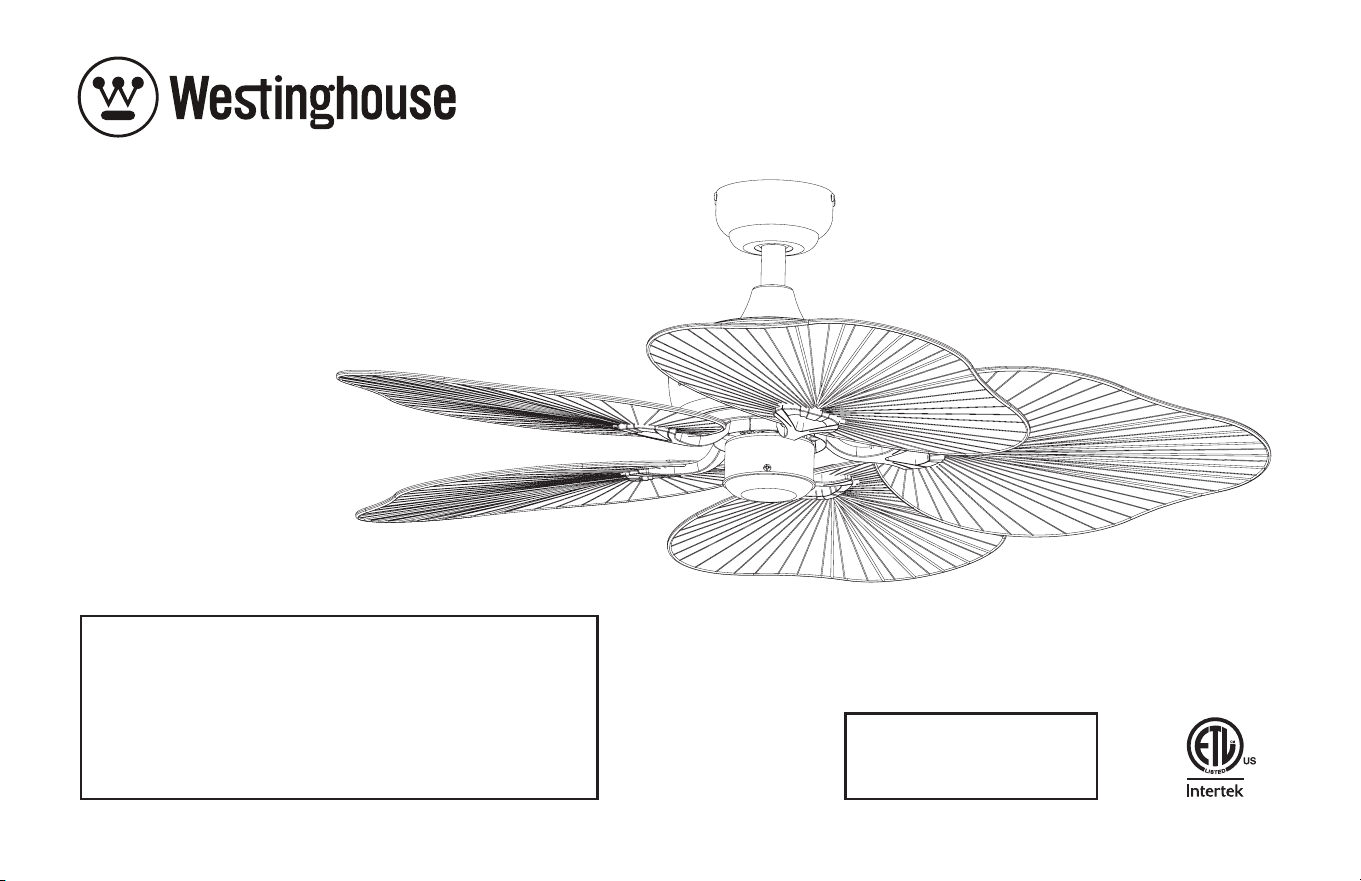
Oasis
Please write model number here for future reference:
Por favor, incluya el número del modelo aquí para futura
referencia:
Net Weight: LBS
Peso Neto: KGS

2
ETL-ES-Oasis-Damp-WH25
TOOLS REQUIRED
Phillips Screwdriver Wire Cutters Pliers Step Ladder
SAFETY TIPS
OBSERVE THE FOLLOWING: READ AND SAVE THESE INSTRUCTIONS
WARNING: TO REDUCE THE RISK OF FIRE, ELECTRIC SHOCK, OR PERSONAL INJURY, MOUNT TO OUTLET BOX MARKED 'ACCEPTABLE FOR FAN SUPPORT OF 35 LBS (15.9 KG) OR LESS'
AND USE MOUNTING SCREWS PROVIDED WITH THE OUTLET BOX AND/OR SUPPORT DIRECTLY FROM BUILDING STRUCTURE. MOST OUTLET BOXES COMMONLY USED FOR THE
SUPPORT OF LUMINARIES ARE NOT ACCEPTABLE FOR FAN SUPPORT AND MAY NEED TO BE REPLACED. CONSULT A QUALIFIED ELECTRICIAN IF IN DOUBT.
1. Installation work and electrical wiring must be done by qualified person(s) in accordance with all applicable codes and standards (ANSI/NFPA 70), including fire-rated construction.
2. Use this unit only in the manner intended by the manufacturer. If you have any questions contact the manufacturer.
3. After making the wire connections, gently push connections into outlet box with wire nuts pointing up. The wires should be spread apart with the grounded conductor and the
equipment-grounding conductor on one side of the outlet box and ungrounded conductor on the other side of the outlet box.
4. Before you begin installing the fan, switch power off at service panel and lock service disconnecting means to prevent power from being switched on accidentally. When the
service disconnecting means cannot be locked, securely fasten a prominent warning device, such as a tag, to the service panel.
5. Be cautious! Read all instructions and safety information before installing your new fan. Review the accompanying assembly diagrams.
6. When cutting or drilling into wall or ceiling, do not damage electrical wiring and other hidden utilities.
7.
Make sure the installation site you choose allows the fan blades to rotate without any obstructions. Allow a minimum clearance of 7 feet from the floor to the trailing edge of the blade.
8. To reduce the risk of fire, electric shock, or personal injury, this fan must be mounted to an outlet box marked suitable for fan support, and use the mounting screws provided with
the outlet box. (Mounting must support at least 35 lbs.)
9. WARNING! Do not bend blade holders during installation to motor, balancing or during cleaning. Do not insert foreign object between rotating blades.
10. Attach the mounting bracket using only the hardware supplied with the outlet box. Fan is only to be mounted to an outlet box marked “Acceptable for Fan Support”.
11. WARNING! To reduce the risk of fire or electric shock, do not use this fan with any solid state fan speed control device, or variable speed control.
12. If this unit is to be installed over a tub or shower, it must be marked as appropriate for the application.
13. NEVER place a switch where it can be reached from a tub or shower.
14. The combustion airflow needed for safe operation of fuel-burning equipment may be affected by this unit’s operation. Follow the heating equipment manufacturer’s guideline safety
standards such as those published by the National Fire Protection Association (NFPA), and the American Society for Heating, Refrigeration and Air Conditioning Engineers (ASHRAE)
and the local code authorities.
15. Before servicing or cleaning unit, switch power off at service panel and lock service disconnecting means to prevent power from being switched on accidentally. When the service
disconnecting means cannot be locked, securely fasten a prominent warning device, such as a tag, to the service panel.
16. All set screws must be checked and re-tightened where necessary before installation.
17. The appliance is not intended for use by young children or infirmed persons without supervision. Young children should be supervised to ensure they do not play with the appliance.
18. Suitable for Indoor/Outdoor Damp Location.

3
ETL-ES-Oasis-Damp-WH25
HERRAMIENTAS NECESARIAS
Destornillador Phillips Pinzas de corte Pinzas Escalera de mano
CONSEJOS DE SEGURIDAD
1. El trabajo de instalación y el cableado eléctrico los deben efectuar personas calificadas cumpliendo con todos los códigos y las normas aplicables (ANSI/NFPA 70), incluyendo las de incendio.
2. Use esta unidad sólo de la manera en que el fabricante quiere que se haga. Si tiene dudas, llame al fabricante.
3. Después de hacer las conexiones, empuje con cuidado las conexiones dentro de la caja de embutir con los conectores de cables mirando hacia arriba. Se deben separar los cables: el conductor de puesta
a tierra y el conductor de puesta a tierra del equipo a un lado de la caja de embutir, y el conductor que no tiene puesta a tierra del otro lado de la misma.
4. Antes de comenzar a instalar el ventilador, apague la alimentación en el panel de servicio y bloquee el medio de desconexión del servicio para evitar que se encienda accidentalmente. Cuando no se puede
bloquear el medio de desconexión del servicio eléctrico, fije de manera segura un dispositivo de advertencia prominente, como un rótulo, al panel de servicio.
5. ¡Tenga cuidado! Lea todas las instrucciones y la información de seguridad antes de instalar su ventilador nuevo. Revise los diagramas de montaje incluidos.
6. Al cortar o perforar una pared o techo, no dañe el cableado eléctrico y otras instalaciones de servicios públicos ocultos.
7. Asegúrese de que el sitio para la instalación que escoja permita que el ventilador gire libremente sin obstrucciones. Deje un espacio mínimo de 7 pies desde le piso hasta el borde posterior de la aleta.
8. Para reducir el riesgo de incendios, choques eléctricos o heridas personales, este ventilador se debe montar sobre una caja de embutir que tenga una marca que indique que es adecuada para soportar un
ventilador. Además debe utilizar los tornillos correspondientes incluidos con la caja de embutir. (El montaje debe soportar por lo menos 35 lbs. (15.9 kgs.).
9. ¡ADVERTENCIA! No doble los soportes para las aletas durante la instalación al motor, al balancear o durante la limpieza. No inserte objetos extraños entre las aletas mientras giran.
10. Fije el soporte de montaje usando sólo la tornillería suministrada con la caja de embutir. El ventilador sólo se debe montar en una caja de embutir marcada “Acceptable for Fan Support”
(Aceptable para soportar ventiladores).
11. ¡ADVERTENCIA! Para reducir el riesgo de incendios o choques eléctricos, no use este ventilador con un dispositivo de control de velocidad de estado sólido para ventilador, o un control de velocidad variable.
12. Si esta unidad se instalará sobre una bañera o una ducha, debe estar identificada como adecuada para ese tipo de aplicación.
13. NUNCA coloque un interruptor donde se pueda alcanzar desde una bañera o una ducha.
14. Es posible que la operación de esta unidad afecte el flujo de aire de combustión necesario para la operación segura de equipo que quema combustible. Siga la directrices de seguridad del fabricante de
equipo de calefacción como las publicadas por la Asociación Nacional de Protección Contra Incendios (National Fire Protection Association, NFPA), y la Sociedad Americana para Ingenieros de Calefacción,
Refrigeración y Aire Acondicionado (American Society for Heating, Refrigeration and Air Conditioning Engineers, ASHRAE) y las autoridades del código local.
15. Antes de efectuar tareas de servicio o limpieza en la unidad, apague la alimentación en el panel de servicio y bloquee el medio de desconexión del servicio para evitar que se encienda accidentalmente.
Cuando no se puede bloquear el medio de desconexión del servicio eléctrico, fije de manera segura y un dispositivo de advertencia prominente, como un rótulo, al panel de servicio.
16. Antes de realizar la instalación, es importante comprobar y volver a ajustar todos los tornillos, según corresponda.
17. El dispositivo no ha sido diseñador para ser utilizado por niños o personas enfermas sin supervisión. Los niños deben ser supervisados para asegurarse de que no juegan con el dispositivo.
18.
Adecuado Para Interiores y Exteriores Ubicación Húmeda.
HAGA LO SIGUIENTE: LEA Y GUARDE ESTAS INSTRUCCIONES
ADVERTENCIA: PARA REDUCIR EL RIESGO DE INCENDIO, DESCARGA ELÉCTRICA O HERIDAS GRAVES PERSONALES, MONTE EN UNA CAJA DE EMBUTIR ROTULADA
'ACCEPTABLE FOR FAN
SUPPORT OF 35 LBS (15.9 KG) OR LESS'
UTILIZANDO LOS TORNILLOS DE MONTAJE INCLUIDOS CON LA CAJA DE EMBUTIR Y/O MONTE DIRECTAMENTE EN LA ESTRUCTURA
DEL EDIFICIO LA MAYORÍA DE LAS CAJAS DE EMBUTIR UTILIZADAS NORMALMENTE CON ARTEFACTOS DE ILUMINACIÓN NO SON ADECUADAS PARA VENTILADORES
Y DEBER
ÍAN SER
REEMPLAZADAS. SI TIENE PREGUNTAS, CONSULTE A UN ELECTRICISTA CALIFICADO
.
4
ETL-ES-Oasis-Damp-WH25
Note: For pitched ceiling installation,
please refer to westinghouselighting.
com for specially designed canopy
kit options.
Nota: Para instalación en techos
inclinados,visite westinghouselight-
ing.com para obtener opciones sobre
equipos de dosel especialmente
diseñados.
FEATURES
CARACTERÍSTICAS
For normal ceilings
Para techos normales
DOWNROD
INSTALLATION
INSTALACIÓN CON
VARILLA VERTICAL
5
ETL-ES-Oasis-Damp-WH25
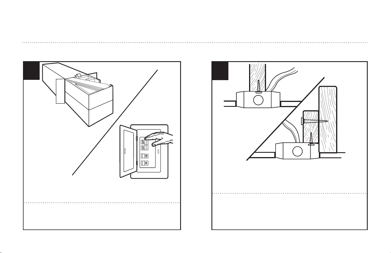
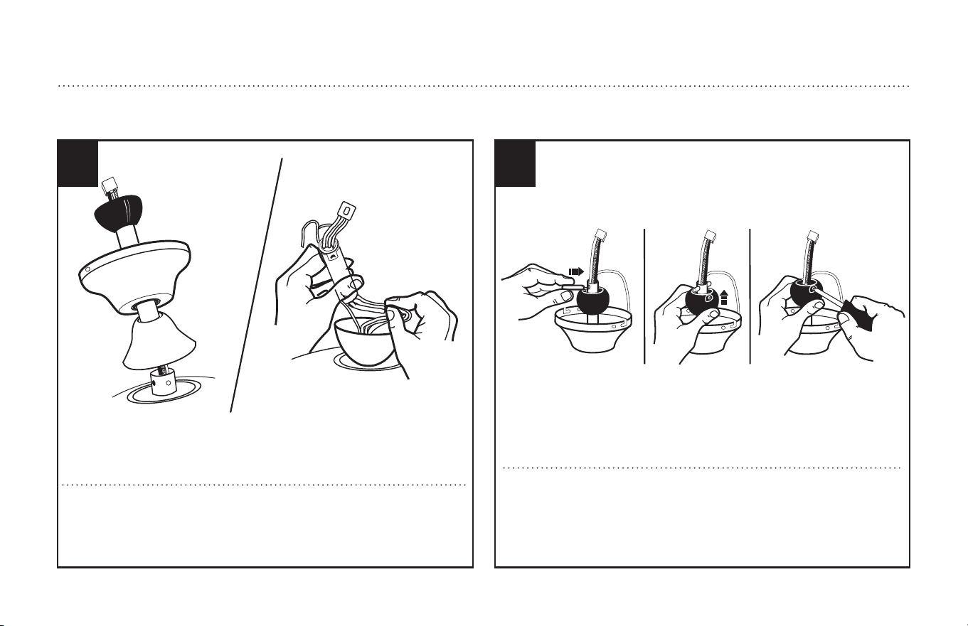
Unpack and inspect fan carefully to be certain all contents are included.
Turn off power at fuse box to avoid possible electrical shock.
1
Use metal outlet box suitable for fan support (must support 35 lbs).
Before attaching fan to outlet box, ensure the outlet box is securely
fastened by at least two points to a structural ceiling member (a loose
box will cause the fan to wobble).
2
PREPARING FOR INSTALLATION
ANTES DE LA INSTALACIÓN
Quite el envoltorio e inspeccione detenidamente el ventilador para veri-
ficar que todas las piezas estén incluidas. Apague la alimentación en la
caja de fusibles para evitar la posibilidad de descarga eléctrica.
Use una caja de embutir de metal adecuada para soportar un ventilador
(debe soportar 35 libras). Antes de fijar el ventilador a la caja de embutir
asegúrese de que la misma esté fijada de manera segura en por lo
menos dos puntos a un miembro estructural del techo (una caja suelta
haría que el ventilador oscile).
6
ETL-ES-Oasis-Damp-WH25
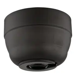
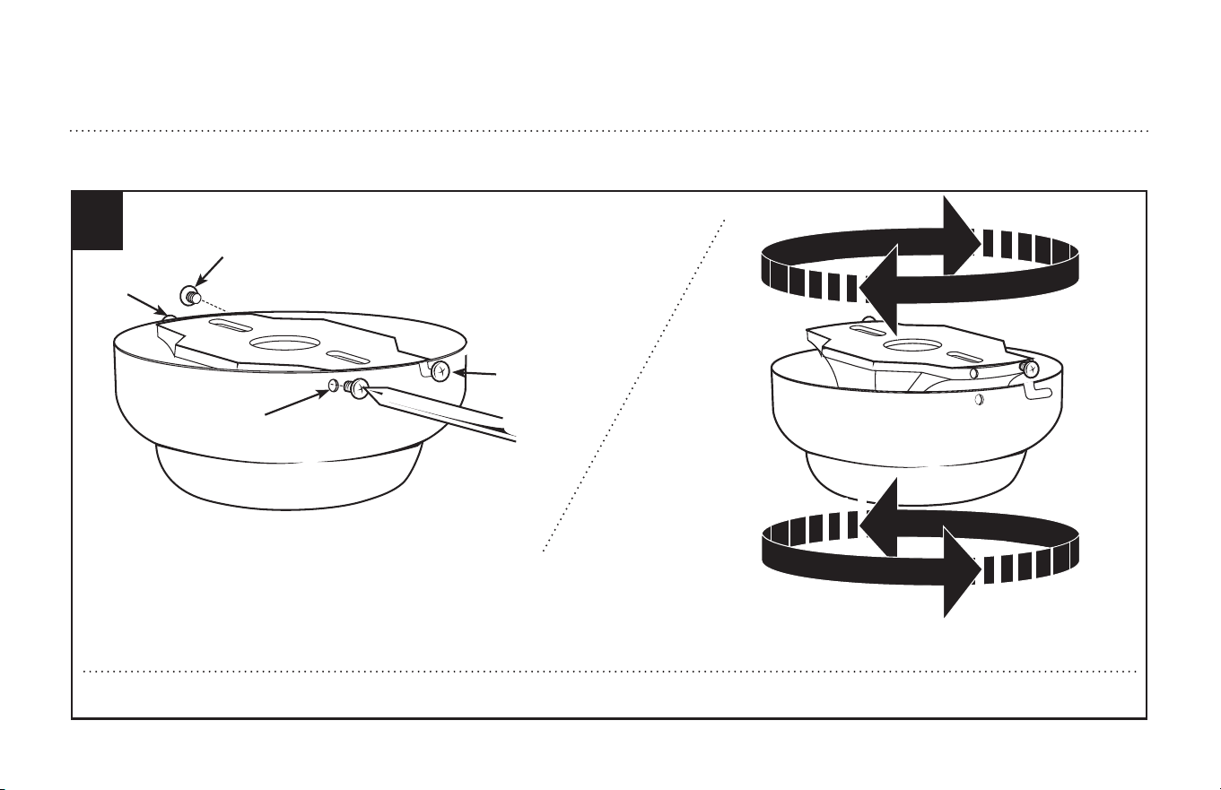
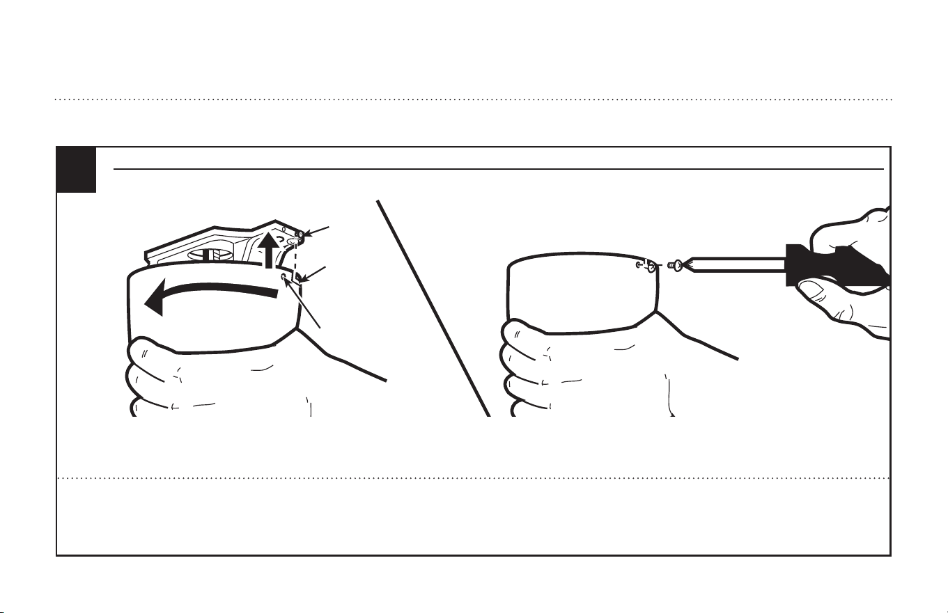
Remove the screws from the two mating holes (2) on the canopy. Loosen (do not remove) the screws in the mating slots (1) on the canopy. Rotate the mounting bracket and
remove from the canopy.
Quite los tornillos de los dos agujeros coincidentes (2) del dosel. Afloje (no quite) los tornillos de las ranuras coincidentes (1) del dosel. Gire el soporte de montaje y sepárelo
del dosel.
2
1
1
2
MOUNTING BRACKET INSTALLATION
INSTALACIÓN CON SOPORTE DE MONTAJE
3
7
MOUNTING BRACKET INSTALLATION
INSTALACIÓN CON SOPORTE DE MONTAJE
4
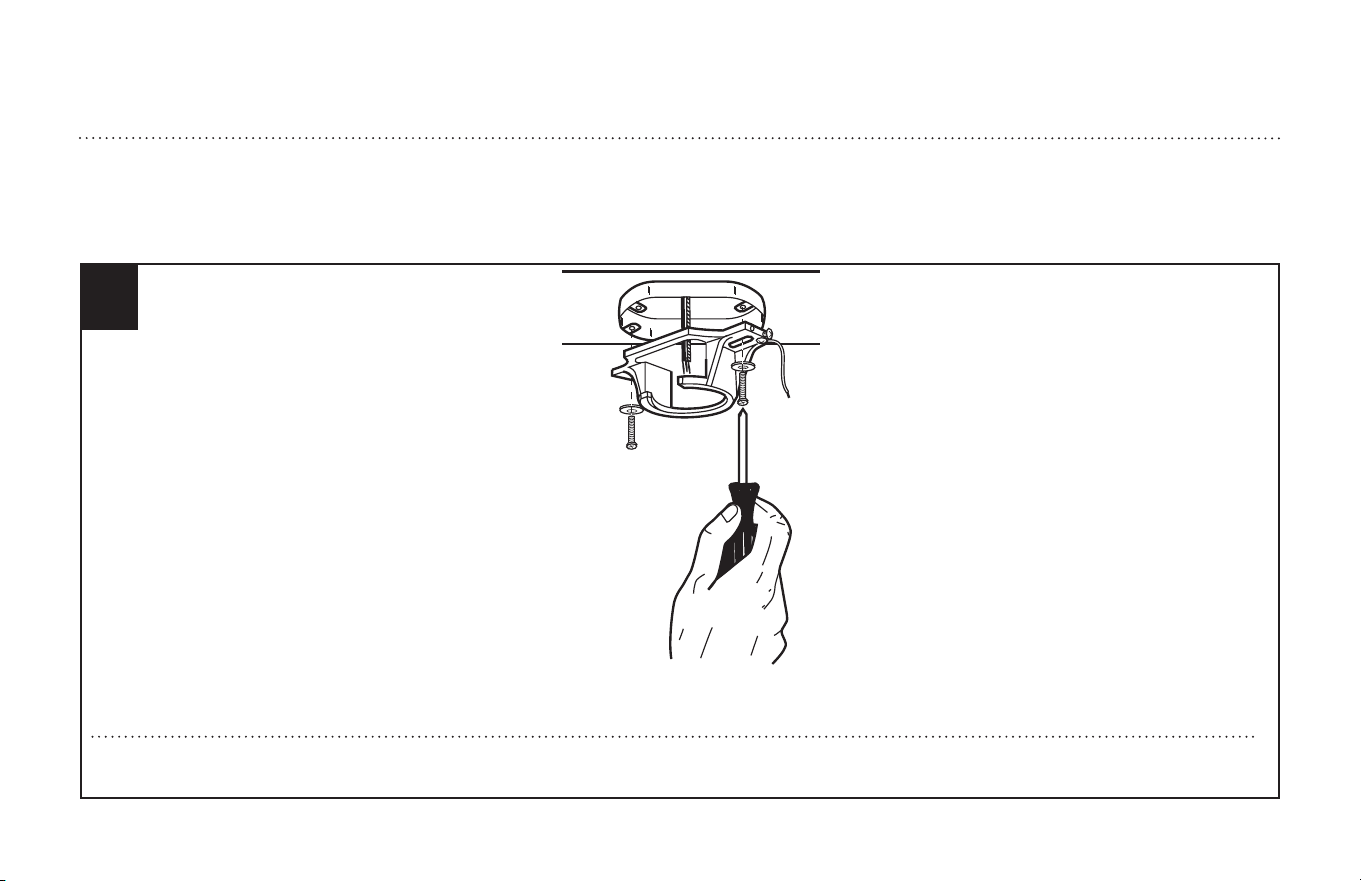
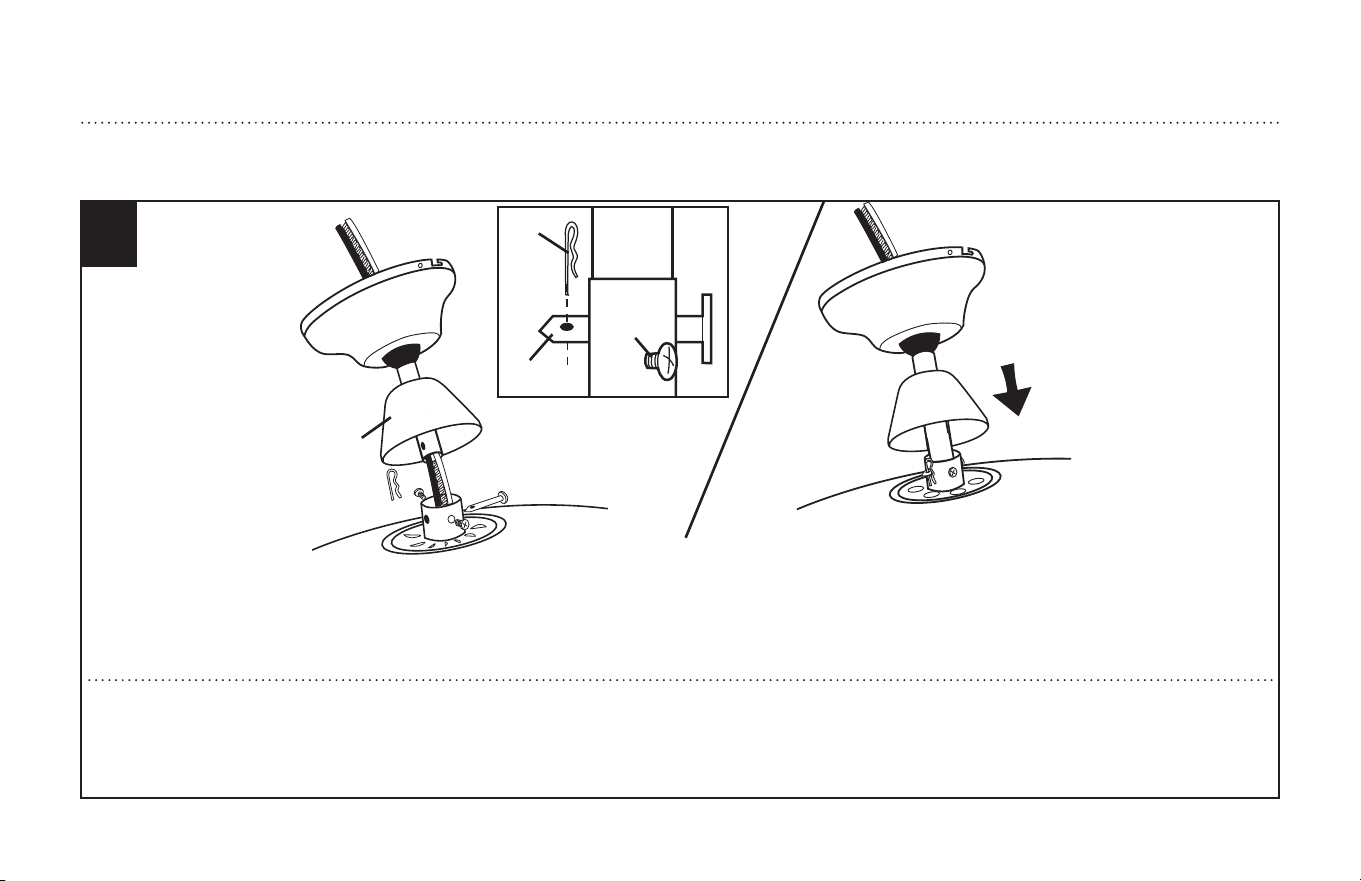
Install mounting bracket to outlet box in ceiling using the screws and washers provided with the outlet box.
Instale el soporte de montaje a la caja de embutir del techo con la tornillería suministrada con la caja de embutir.
ETL-ES-Oasis-Damp-WH25
8
ETL-ES-Oasis-Damp-WH25
5
2
1
3
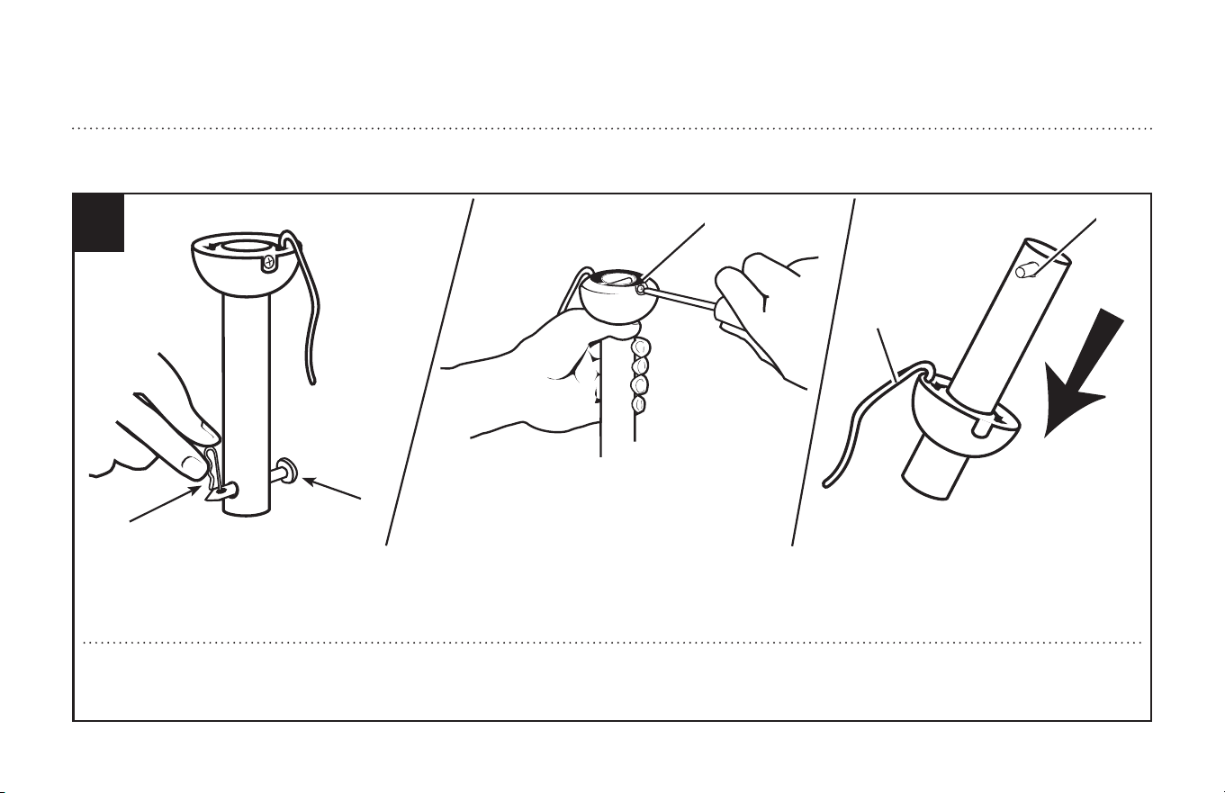
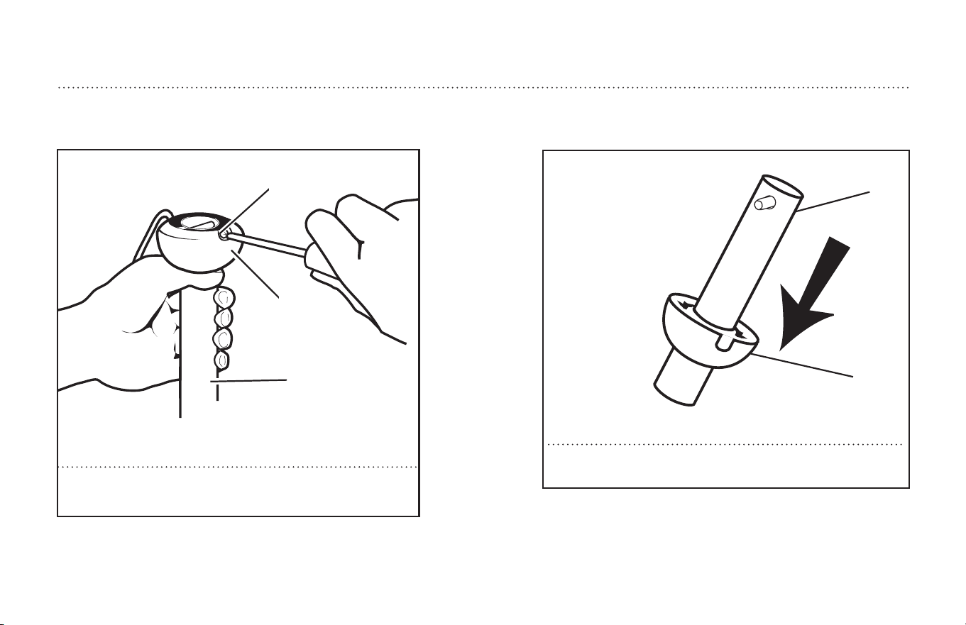
Remove clamp pin (2) and cross pin (1) from down rod. Loosen set screws in down rod ball (3) until ball moves easily up and down the down rod. Do not remove
groundwire (4) from ball. Slide down rod ball down, exposing cross pin (5). Do not remove ball completely. Remove cross pin and save for later use.
Quite el pasador de fijación (2) y el pasador transversal (1) de la varilla vertical. Afloje el tornillo de fijación en la bola de la varilla vertical (3) hasta que la bola se
mueva fácilmente hacia abajo y arriba por la varilla vertical. No extraiga el cable de puesta a tierra (4) de la varilla vertical. Deslice hacia abajo la bola de la varilla
vertical, exponiendo el pasador transversal (5). No extraiga completamente la bola. Extraiga el pasador transversal y guárdelo para usarlo más tarde.
5
4
DOWNROD PREPARATION
PREPARACION DE LA VARILLA VERTICAL
9
ETL-ES-Oasis-Damp-WH25
DOWNROD INSTALLATION
INSTALACION DE LA VARILLA VERTICAL
Insert the down rod or extended down rod through the canopy and coupling
cover. Carefully thread lead wires and plug though the down rod and ball
assembly.
Note: contact a qualified electrician to install an appropriate extended cord for
the extended down rod installation.
Inserte la varilla vertical o la varilla vertical extendida a través de la cubierta y
la cubierta de acoplamiento. Enrosque cuidadosamente los cables y el enchufe
a través del conjunto de varilla y bola hacia abajo.
Nota: comuníquese con un electricista calificado para instalar un cable exten-
dido apropiado para el Instalación de varilla vertical extendida.
Re-install cross pin into down rod and slide down rod ball up until cross pin
fits firmly into ball. Tighten set screws in ball. Note: For the extended down
rod, assemble the down rod ball from step # 10 to down rod, slide down rod
ball up to the top of the down rod.
Vuelva a instalar el pasador transversal en la varilla vertical y deslice hacia arriba la
bola de la varilla vertical hasta que el pasador calce firmemente dentro de la bola.
Ajuste el tornillo de fijación en la bola.
Nota: Para la varilla vertical extendida, ensamble la bola de la varilla vertical
del paso # 10 hasta la varilla vertical, deslice la bola de la varilla verftical
hasta la parte superior de la varilla vertical.
76
10
ETL-ES-Oasis-Damp-WH25
NORMAL DOWNROD OPTION
OPCIÓN CON VARILLA VERTICAL NORMAL
8
1
4
3
2
Choose a MOUNTING OPTION, either Normal Downrod Option using the included downrod, or Extended Downrod Option using a longer downrod (purchased separately).
Insert motor wires through the selected downrod and insert the downrod into the downrod coupling. Make sure to align the hole in the downrod with the hole in the
downrod coupling. Install cross pin (1) removed in step 5 through coupling and downrod. Insert clamp pin (2) into cross pin until it snaps into place. Tighten set screws
(3) in coupling. Slide coupling cover (4) and canopy onto the downrod above the coupling cover. SEE APPENDIX FOR ALTERNATE INSTALLATION OPTIONS ON PAGE 19.
Elige una OPCIÓN DE MONTAJE, opción con varilla vertical para techo normal ó la opción con varilla vertical más larga. Inserte los cables del motor a través del conjunto
de la varilla vertical y inserte la varilla vertical en el acoplamiento de la varilla vertical. Asegúrese de que el agujero de la varilla vertical y el del acoplamiento de la
varilla vertical estén alineados. Instale el pasador transversal (1) pasándolo por el acoplamiento y la varilla vertical. Inserte el pasador tipo prensa (2) en el pasador
transversal hasta que escuche un chasquido que indique que está en la posición adecuada. Ajuste los tornillos de fijación (3) en el acoplamiento. Deslice la cubierta del
acoplamiento (4) sobre el acoplamiento de la varilla vertical. CONSULTE EL APÉNDICE PARA CONOCER LAS OPCIONES DE INSTALACIÓN ALTERNATIVAS EN LA PAGINA 19.
11
ETL-ES-Oasis-Damp-WH25
9
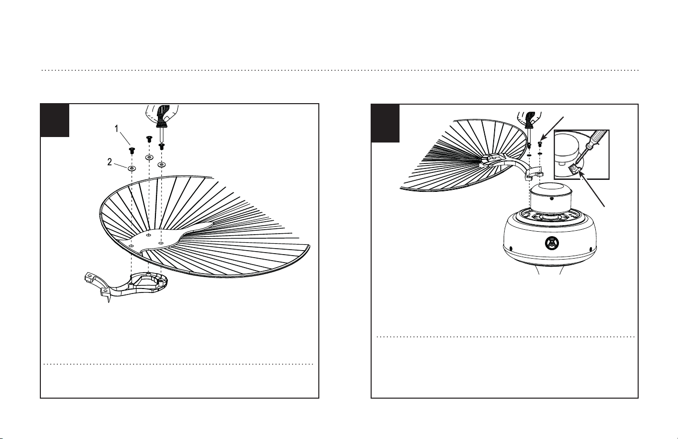
Attach blade brackets to blades using the blade bracket screws (1) and
fabric washers (2), if provided. NOTE: Some models do not utilize fabric
washers (2).
Fije los soportes para aletas a las aletas con los tornillos (1) y las de tela (2)
si corresponde. NOTA: Algunos modelos no utilizan arandelas de tela (2).
BLADE INSTALLATION
INSTALACIÓN DE LAS ALETAS
Check the motor for plastic shipping stabilizer tabs (1), and remove
them if they are present. Attach blade assembly to motor using the
noise-dampening motor gaskets and motor screws (2) provided. Tighten
screws ecurely. NOTE: Some models do not utilize motor gaskets,
washers, or stabilizer tabs.
Verifique si hay lengüetas plásticas de embalaje para sostener al motor (1) y
descártelas. Fije el conjunto de las aletas al motor usando las juntas reduc-
toras de sonido del motor (2) y los tornillos para el motor incluidos. Apriete
los tornillos asegurándolos. NOTA: Algunos modelos no utilizan juntas para
el motor, arandelas o lengüetas de embalaje.
10
1
2
12
ETL-ES-Oasis-Damp-WH25
11
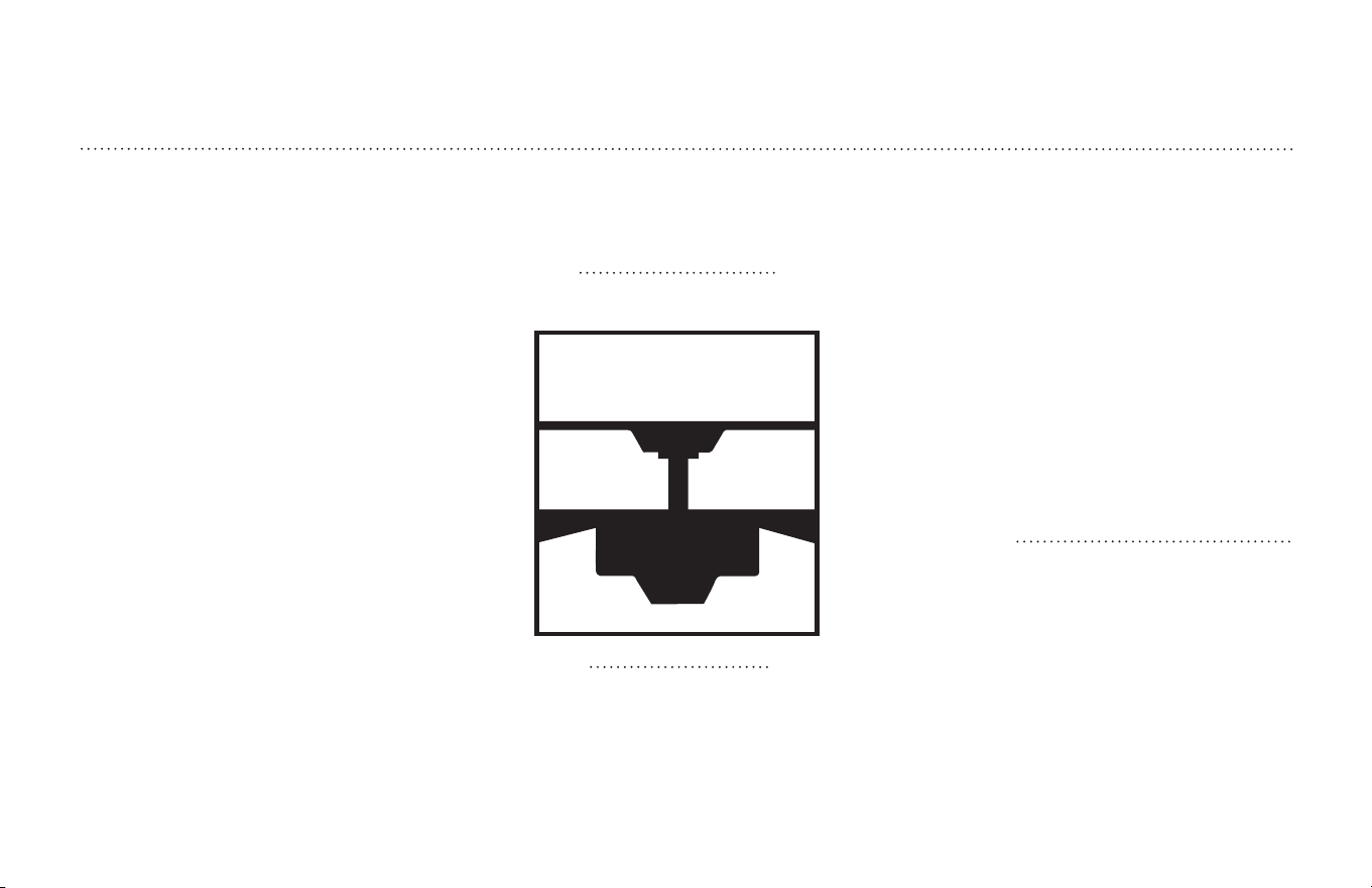
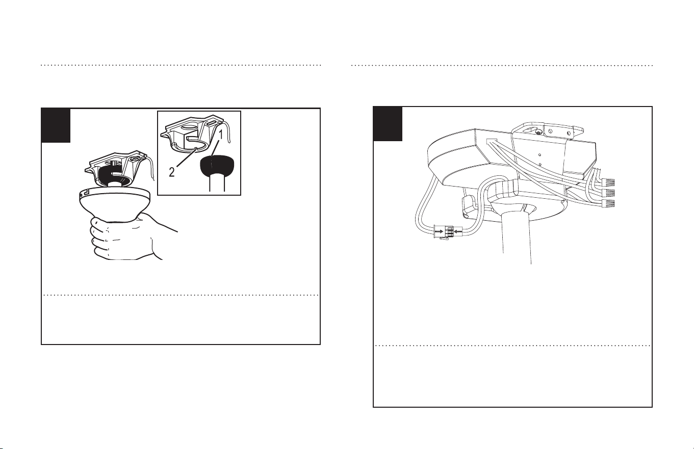
Carefully lift fan assembly onto mounting bracket. Rotate fan until notch
on downrod ball (1) engages the ridge on the mounting bracket (2). This
will allow for hands free wiring.
Levante con cuidado el conjunto del ventilador hasta el soporte de mon-
taje. Gire el ventilador hasta que la muesca de la bola de la varilla vertical
(1) calce sobre la saliente del soporte de montaje (2). De este modo, ten-
drá las dos manos libres para hacer el cableado.
MOUNTING
MONTAJE
WIRING OPTIONS
OPCIÓN DE CABLEADO
12
After hanging fan onto the mounting bracket, make sure plug connector
from the ceiling fan and lead wire from supply wires are moved away
from the space located above the down rod ball. Slide the remote receiver
into the space above the down rod ball as shown.
Después de colgar el ventilador en el soporte de montaje, asegúrese de
que el conector del ventilador y el cable conductor se alejan del espacio
situado por encima de la bola de la varilla vertical. Deslice el receptor
remoto en el espacio encima de la bola de la varilla vertical como se
muestra.
13
ETL-ES-Oasis-Damp-WH25
WIRING OPTIONS
OPCIÓN DE CABLEADO
13
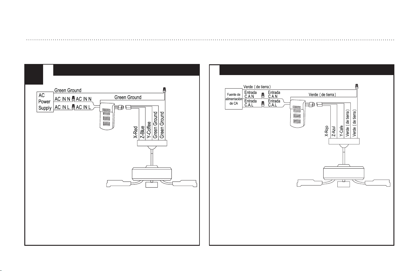
Mientras el ventilador cuelga del soporte, enchufe el conector de 4 polos del
ventilador al conector de 6 polos del receptor remoto. Conecte el cable del
receptor al Cable de la carcasa mediante tuerca de cable suministrada, el cable
blanco del receptor remoto al cable neutro de la casa y el cable negro del recep-
tor al cable línea (vivo) de la casa. Conecte el cable de tierra verde del soporte
de montaje y la bola de la varilla vertical a la de cobre pelado o cable de tierra
verde.
REMOTE CONTROL WIRING OPTION
OPCIÓN DE CABLEADO PARA CONTROL REMOTO
While fan is hanging on bracket, plug 4-pole connector from the fan into
the 6-pole plug connector from the remote receiver. Connect the wire from
receiver to the wire from the housing by wire nut supplied, the remote
receiver's white wire to the house neutral wire and the receiver's black wire
to the house line (hot) wire. Connect the green ground wire from the mount-
ing bracket and down rod ball to the bare copper or green ground wire from
the supply wires.
SECURE TO CEILING
ASEGURE EL VENTILADOR AL TECHO
14
The canopy has two mating slots (1) and two mating holes (2). Position both slots on canopy directly under and in line with two screws in the mounting bracket (3). Lift the
canopy, allowing the two screws to slide into the mating slots. Rotate the canopy until both screws from the mounting bracket drop into the slot recesses. Tighten screws
securely. Install two screws into the mating holes of the canopy and tighten to secure the canopy to the mounting bracket.
El dosel tiene dos ranuras coincidentes (1) y dos agujeros coincidentes (2). Coloque ambas ranuras del dosel directamente abajo y en línea con los dos tornillos del
soporte de montaje (3). Eleve el dosel, permitiendo que los dos tornillos se deslicen dentro de las ranuras. Gire el dosel hasta que ambos tornillos del soporte de
montaje caigan dentro de las ranuras. Apriete los tornillos asegurándolos. Instale los dos tornillos en los agujeros coincidentes del dosel y ajústelos para asegurar
el dosel al soporte de montaje.
2
3
1
For downrod fans, slide the canopy up to the mounting bracket.
Para ventiladores con varilla vertical, deslice el dosel hacia arriba hasta el soporte de montaje.
14
ETL-ES-Oasis-Damp-WH25
15
ETL-ES-Oasis-Damp-WH25
HOW TO OPERATE YOUR CEILING FAN
INSTRUCCIONES PARA OPERAR SU VENTILADOR DE TECHO
1
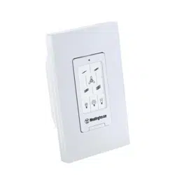
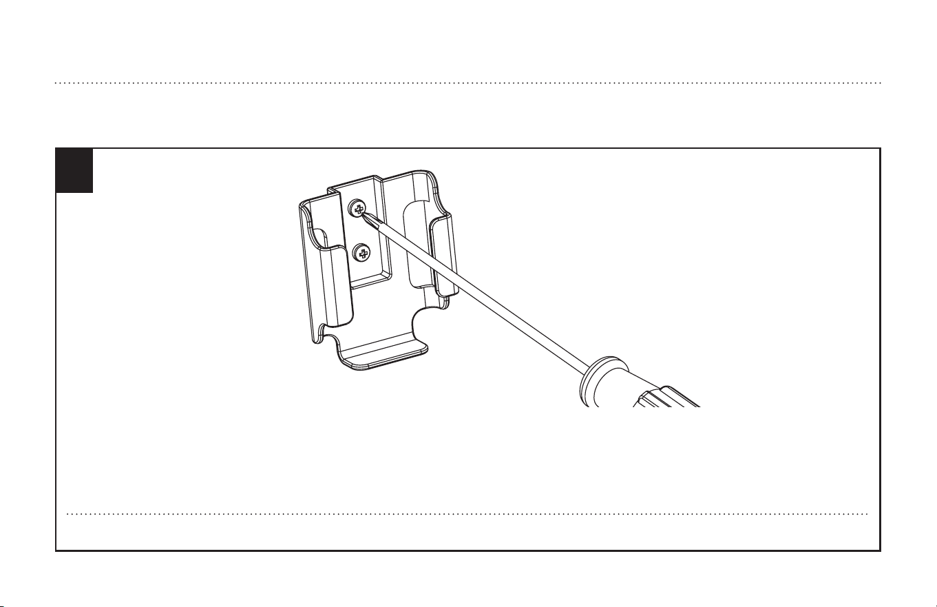
Mount the transmitter holder onto the wall using screws provided. Place the transmitter into the holder.
Monte el soporte para el transmisor a la pared usando los tornillos incluidos. Coloque el transmisor en el soporte.
16
ETL-ES-Oasis-Damp-WH25
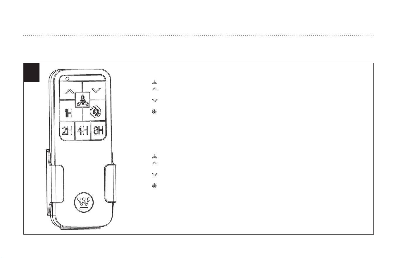
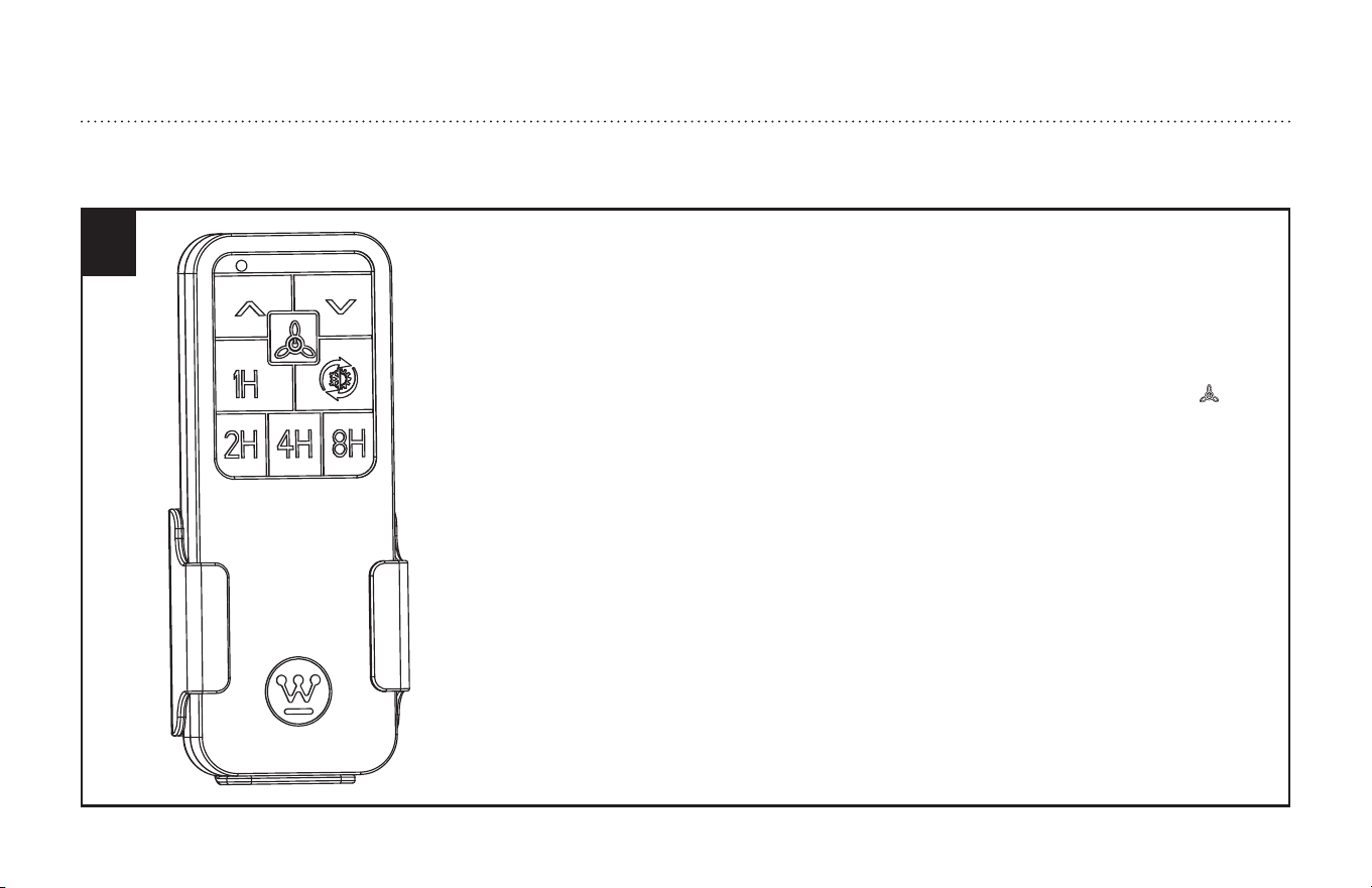
Remote Control Operation
The remote buttons function as follows:
1. Symbol from the transmitter - press and release reflects the fan ON/OFF function.
2. Symbol from the transmitter-Speed up button, continuously press & release the button, controls
the fan speeds from the lowest/1 speed to the highest/6 speed.
3. Symbol from the transmitter-Speed down button,continuously press & release the button,
controls the fan speeds from the highest/6 speed to the lowest/1 speed.
4. Symbol from the transmitter-Reversible switch button, press and release the button controls
direction, forward or reverse.
5. Operation duration time (1H,2H,4H &8H hours setting).
6. LED indicated light. Pressed the button, the LED lighting.
Operación con control remoto
Los botones del control remoto funcionan de la siguiente manera:
1. Símbolo del transmisor: presionar y soltar refleja el ventilador ENCENDIDO / APAGADO función.
2. Símbolo del transmisor: botón para aumentar la velocidad. Presione y suelte el botón continuamente.
Controla la velocidad del ventilador desde la velocidad más baja/1 hasta la velocidad más alta/6.
3. Símbolo del transmisor: botón para disminuir la velocidad. Presione y suelte el botón continuamente.
Controla la velocidad del ventilador desde la velocidad más alta/6 hasta la velocidad más baja/1.
4. Símbolo del transmisor: botón de interruptor reversible. Presione y suelte el botón.
Controla la dirección, hacia adelante o hacia atrás.
5. Tiempo de duración de funcionamiento (configuración de 1h, 2h, 4h y 8h).
6. Luz con LED. Presione el botón, iluminación LED.
HOW TO OPERATE YOUR CEILING FAN
INSTRUCCIONES PARA OPERAR SU VENTILADOR DE TECHO
2

17
ETL-ES-Oasis-Damp-WH25
3
Restore electrical power to the outlet box by turning on the electricity at the main fuse box.
To make the fan operational, open battery door by pressing and sliding down the battery door.
Install two AAA 1.5V batteries (not included) into the hand-held remote transmitter (if not used for
long periods of time, remove the batteries to prevent damage to the transmitter).
1. The remote control adopts RF wireless digit emission technique.
2. The transmitter and receiver are matched at the factory. Please follow the next step to repair when
the pairing is failed.
3. Turn off the fan power and then restore it, press and hold the " " button for 5 seconds, within 30
seconds after you restore the power, the fan will automatic turn on at low speed and then
turn off, with the light flashing 2 times.
(NOTE: The pairing process is not accepted after 30 seconds when you restore supply power)
4. Please note that the transmitter can pair with multiple receivers. When the transmitter does not
control the receiver, please check if any similar remote controls are working nearby, disconnect
them and then proceed with pairing process again.
5. Store the remote transmitter away from excessive heat or humidity.
6. Low power of battery or not-used for long time should be replaced.
7. The remote control has memory function, it will remember the previous fan speed setting when
power is restored to the fan by an external ON/OFF wall switch.
HOW TO OPERATE YOUR CEILING FAN
INSTRUCCIONES PARA OPERAR SU VENTILADOR DE TECHO
18
ETL-ES-Oasis-Damp-WH25
3
Restaure la energía eléctrica a la caja de embutir encendiendo la electricidad en la caja de fusibles
principal. Para que el ventilador funcione, abra la puerta de la batería presionando y deslizándola
hacia abajo. Instale dos baterías AAA de 1,5 V (no incluido) en el transmisor remoto de mano (si no
se utiliza durante mucho tiempo, retire las baterías para evitar daños al transmisor).
1. El control remoto adopta la técnica de emisión de dígitos inalámbrica de RF.
2. El transmisor y el receptor se emparejan en la fábrica. Siga el siguiente paso para reparar cuando
el emparejamiento ha fallado.
3. Apague el ventilador y luego restablézcalo, presione y mantenga presionado el botón " "
durante 5 segundos, dentro de los 30 segundos posteriores a la restauración de la energía, el
ventilador se encenderá automáticamente a baja velocidad y luego apagar, con la luz
parpadeando 2 veces.
(NOTA: El proceso de emparejamiento no se acepta después de 30 segundos cuando restablece
la alimentación)
4. Tenga en cuenta que el transmisor puede emparejarse con varios receptores. Cuando el
transmisor no controle el receptor, compruebe si hay controles remotos similares funcionando
cerca, desconéctelosy luego continúe con el proceso de emparejamiento nuevamente.
5. Guarde el transmisor remoto lejos del calor o la humedad excesivos.
6. Debe reemplazarse la batería baja o no utilizada durante mucho tiempo.
7. El control remoto tiene función de memoria, recordará la configuración de velocidad del
ventilador cuando restablezca la energía mediante un interruptor de pared externo de
ENCENDIDO/APAGADO.
HOW TO OPERATE YOUR CEILING FAN
INSTRUCCIONES PARA OPERAR SU VENTILADOR DE TECHO

19
ETL-ES-Oasis-Damp-WH25
Appendix for alternate installation options
EXTENDED DOWNROD OPTION (see page # 20 to page #21)
Apéndice para opciones de instalación alternativas
OPCIÓN CON VARILLA VERTICAL MÁS LARGA (consulte a la página # 20 a la página #21)
20
ETL-ES-Oasis-Damp-WH25
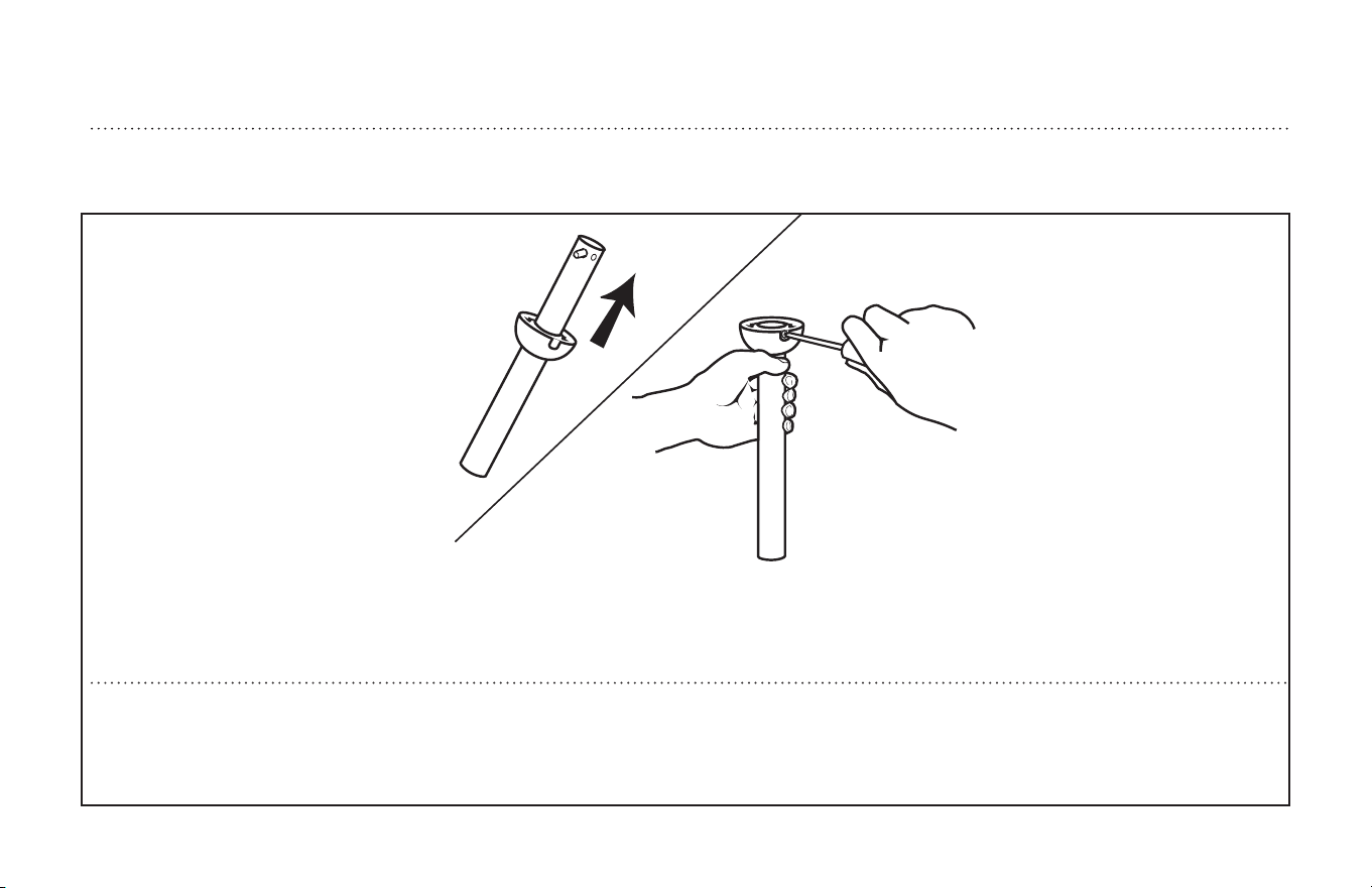
Loosen downrod ball (1) from downrod (2) by removing set screw (3).
Afloje la bola de la varilla vertical (1) de la varilla vertical (2)
quitando el tornillo (3).
2
3
1
EXTENDED DOWNROD OPTION
OPCIÓN CON VARILLA VERTICAL MÁS LARGA
Slide downrod ball (1) off of downrod and remove pin (2).
Deslice la bola de la varilla vertical (1) hasta separarla de la varilla vertical
y quite el pasador (2).
2
1
21
ETL-ES-Oasis-Damp-WH25
EXTENDED DOWNROD OPTION
OPCIÓN CON VARILLA VERTICAL MÁS LARGA
Re-install pin into extended downrod, and slide downrod ball up to the top of the downrod. Re-install set screw to secure ball to downrod. Note: Some
extended downrods have a pre-drilled set-screw hole. If a pre-drilled hole is present in the extended downrod, tighten the set screw into the pre-drilled
hole in the extended downrod. If no pre-drilled hole exists in the extended downrod, tighten the set screw against the downrod to secure the downrod
ball. PROCEEDTO PAGE 10, STEP 8.
Vuelva a instalar el pasador en la varilla vertical más larga y deslice la bola de la varilla hasta el extremo superior de la misma. Vuelva a insertar el tornillo
de fijación para asegurar la bola a la varilla vertical. Nota: Algunas varillas verticales más largas tienen un agujero previamente perforado para el tornillo. Si
la varilla vertical más larga tiene un agujero previamente perforado, ajuste el tornillo en el agujero previamente perforado de la varilla vertical más larga. Si
la varilla vertical más larga no tiene un agujero previamente perforado, ajuste el tornillo sobre la varilla vertical para asegurar la bola de la misma. PROCEDA
A LA PÁG. 10, PASO 8.
22
ETL-ES-Oasis-Damp-WH25
Operation
Turn on the power and check operation of fan.
Speed settings for warm or cool weather depend on factors such as room size, ceiling height, number of fans and so on.
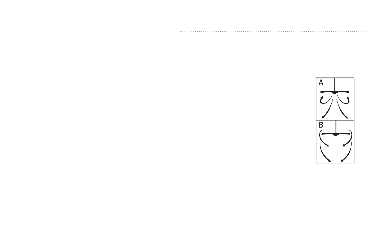
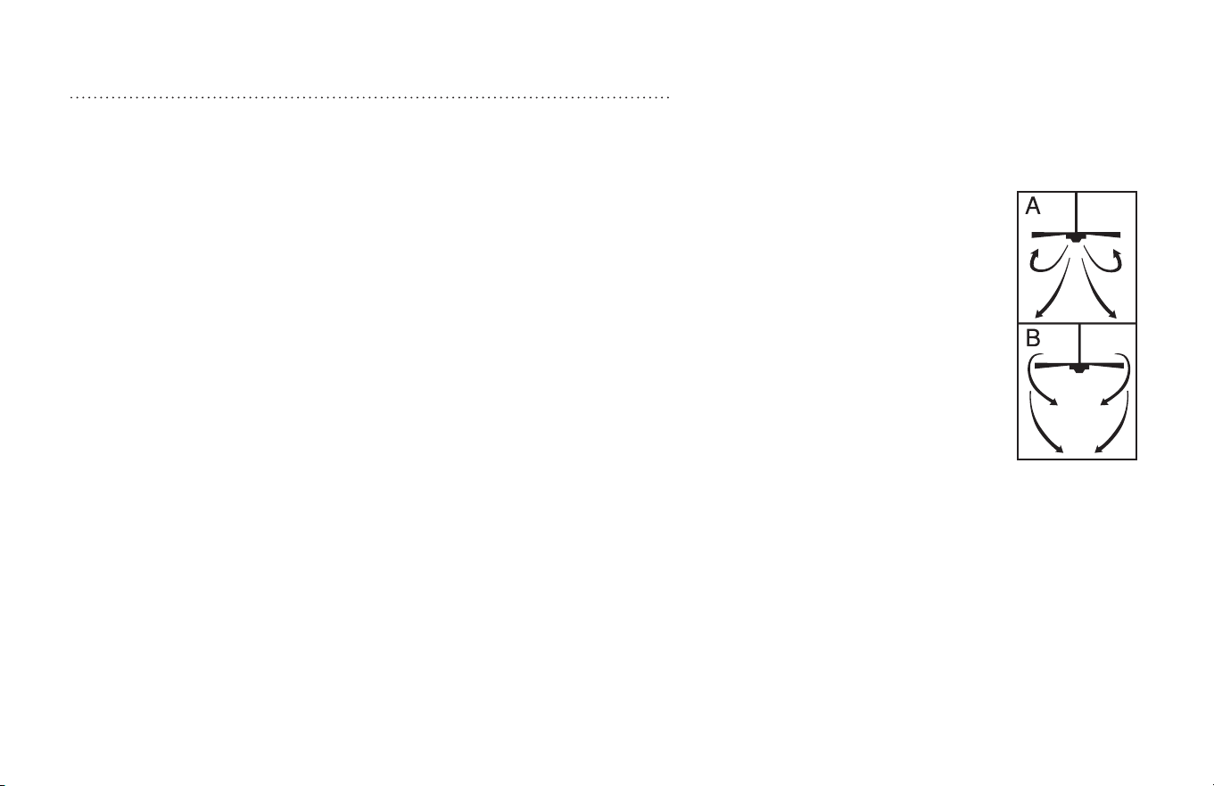
The slide switch controls direction, forward or reverse.
Warm weather/down position - (Forward) Fan turns counterclockwise direction. A downward air flow creates a cooling effect as shown in
illustration A. This allows you to set your air conditioner on a higher temperature setting without affecting your comfort.
Cool weather/up position - (Reverse) Fan turns clockwise direction. An upward airflow moves warm air off the ceiling area as shown in
illustration B. This allows you to set your heating unit on a lower setting without affecting your comfort.
Maintenance
1. Because of the fan’s natural movement, some connections may become loose. Check the support connections, brackets, and blade
attachments twice a year. Make sure they are secure.
2. Clean your fan periodically to help maintain its new appearance over the years. Do not use water when cleaning.
This could damage the motor, or the wood, or possibly cause electrical shock.
3. Use only a soft brush or lint-free cloth to avoid scratching the finish. The plating is sealed with a lacquer coating to minimize
discoloration or tarnishing.
4. There is no need to oil your fan. The motor has permanently lubricated bearings.
OPERATION AND MAINTENANCE
23
ETL-ES-Oasis-Damp-WH25
Operación
Encienda el ventilador y verifique su funcionamiento.
Las velocidades para clima cálido o frío dependen de factores como el tamaño de la habitación, la altura del ventilador, el número de
ventiladores, etc.
El interruptor deslizante controla la dirección, hacia adelante o hacia atrás.
Clima cálido/posición hacia abajo - (Adelante) El ventilador gira en sentido contrahorario. Una corriente de aire descendente crea un efecto
refrescante como lo indica la ilustración A. Esto le permite ajustar el aire acondicionado a una temperatura más alta sin que afecte su
comodidad.
Clima frío/posición hacia arriba - (Atrás) El ventilador gira en sentido de las agujas del reloj. Una corriente de aire ascendente aleja el aire
caliente del área del ventilador de techo como lo indica la ilustración B. Esto le permite ajustar la calefacción a un nivel más bajo sin que afecte
su comodidad.
Mantenimiento
1. El movimiento natural del ventilador podría hacer que se aflojen algunas conexiones. Verifique las conexiones de soporte, las piezas de
fijación y los accesorios de las aletas dos veces al año. Cerciórese de que estén aseguradas.
2. Limpie el ventilador periódicamente para ayudar a mantener su apariencia nueva con el correr de los años. No use agua para limpiarlo,
ya que podría dañar el motor o la madera o causar descarga eléctrica.
3. Use sólo un cepillo blando o un trapo sin pelusa para no rayar el acabado. El enchapado está sellado con una capa de laca para minimizar la
decoloración o pérdida del brillo.
4. No hay necesidad de aceitar el ventilador. El motor tiene cojinetes de lubricación permanente.
OPERACIÓN Y MANTENIMIENTO

24
ETL-ES-Oasis-Damp-WH25
TROUBLESHOOTING
GUIDE
If you have difficulty operating your new ceiling fan, it may be the result of incorrect assembly, installation, or
wiring. In some cases, these installation errors may be mistaken for defects. If you experience any faults,
please check this Trouble Shooting Chart. If a problem cannot be remedied, please consult with your qualified
electrician and do not attempt any electrical repairs yourself.
TROUBLE SUGGESTED REMEDY
1. If fan does not start: 1. check main and branch circuit fuses or circuit breakers.
2. check wire connections as performed in step #13 of installation.
CAUTION: Make sure main power is turned off.
3. Make sure forward/reverse switch is firmly in up or down position.
Fan will not operate when switch is in the middle.
4. If the fan still will not start, contact a qualified electrician.
Do not attempt to troubleshoot internal electrical connections yourself.
2. If fan sounds noisy: 1. check to make sure all screws in motor housing are snug (not over tightened).
2. check to make sure the screws which attach the fan blade holder to the motor are tight.
3. Some fan motors are sensitive to signals from Solid State variable speed controls.
DO NOT USe a Solid State variable speed control.
4. Allow “break-in” period of 24 hours. Most noises associated with a new fan will disappear after this period.
3. If fan wobbles: All blades are weighed and grouped by weight. Natural woods vary in density which could cause the fan to wobble even though all blades
are weight-matched. The following procedures should eliminate most of the wobble. check for wobble after each step.
1. check that all blades are screwed firmly into blade holders.
2. check that all blade holders are tightened securely to motor.
3. Make sure that canopy and mounting bracket are tightened securely to ceiling joist.
4. If blade wobble is still noticeable, interchanging two adjacent (side by side) blades can redistribute the weight and possibly result in
smoother operation.

25
ETL-ES-Oasis-Damp-WH25
GUÍA PARA SOLUCIONAR
PROBLEMAS
Si tiene dificultades para hacer funcionar su nuevo ventilador, podría ser a causa del
armado, instalación o cableado incorrectos. En algunos casos, estos errores de
instalación podrían ser confundidos con defectos. Si experiencia algun fallo, consulte
esta guía para solucionar problemas. Si no puede solucionar el problema, consulte a un
electricista calificado y no intente reparar conexiones eléctricas.
PROBLEMA
1. Si el ventilador no
arranca:
2. Si el ventilador es
ruidoso:
3. Si el ventilador oscila:
SOLUCIÓN SUGERIDA
1. Compruebe los fusibles o disyuntores principales y del circuito derivado.
2.Compruebe el cableado del bloque de terminales como lo hizo en el paso No. 13 de la instalación.
ADVERTENCIA: Asegúrese de que la alimentación principal esté apagada.
3. Asegúrese de que el interruptor de marcha adelante/atrás esté firmemente en su posición.
El ventilador no funcionará si el interruptor está en el medio.
4.Si el ventilador no arranca, póngase en contacto con un electricista calificado. No intente reparar conexiones eléctricas internas.
1. Compruebe para asegurarse de que todos los tornillos del alojamiento del motor estén ajustados (no los apriete demasiado).
2.Compruebe para asegurarse de que los tornillos que fijan el soporte de la aleta del ventilador al motor estén apretados.
3. NO USE un control de velocidad variable de estado sólido.
4.Permita el "rodaje" del ventilador durante un período de 24 horas. La mayoría de los ruidos asociados con el ventilador nuevo desaparecerán
después de este período.
Todas las aletas se pesan y agrupan según el peso. Las maderas naturales varían en densidad y podrían hacer que el ventilador oscile aún cuando
todas las aletas estén agrupadas por peso. Los siguientes procedimientos deberían eliminar la mayoría de los problemas de oscilación. Verifique la
oscilación después de cada paso.
1. Verifique que todas las aletas estén firmemente atornilladas a los soportes de las aletas.
2.Verifique que todos los soportes de las aletas estén firmemente aseguradas al motor.
3. Asegúrese de que el dosel y el soporte de montaje estén firmemente asegurados a la viga del techo.
4.Si la oscilación de la aleta sigue siendo visible, es posible que al intercambiar dos aletas adyacentes (lado a lado) se redistribuya el peso y el
funcionamiento sea más suave.

26
ETL-ES-Oasis-Damp-WH25
WARRANTY
This Westinghouse Lighting Fan offers a Limited Lifetime Warranty to the original owner against defects in material and workmanship.
This warranty is in lieu of all other warranties expressed or implied.
Westinghouse Lighting will repair or replace the parts needed, and/or, replace the ceiling fan, if the defective is due to faulty materials or workmanship.
Years 1 & 2 – Westinghouse Lighting will repair or replace this ceiling fan.
After Year 2 – Warranty is limited to the motor.
This warranty does not cover acts of nature such as lightning damage, or corrosion and discoloration of components, nor does it cover damages caused through
abuse, improper installation, surges in electric current, or acts of third parties. This warranty does not cover broken glass after installation. If this ceiling fan fails
during the warranty period, return defective product to seller. Warranty terms and conditions of sellerr apply. If replacement product is not available through seller,
please contact www.westinghouselighting.com/contact-us.
GARANTÍA
Este ventilador de Westinghouse Lighting se ofrece con una garantía limitada de por vida para el propietario original frente a defectos de material y de mano de obra.
Esta garantía sustituye cualquier otra garantía expresa o implícita.
Westinghouse Lighting reparará o reemplazará las piezas necesarias y/o reemplazará el ventilador de techo si el fallo se debe a defectos de material o de mano de
obra.
Primeros 2 años: Westinghouse Lighting reparará o reemplazará este ventilador de techo.
Después del segundo año: la garantía queda limitada al motor.
Esta garantía no cubre los daños debidos a fenómenos naturales, como daños por caída de rayos, corrosión o decoloración de los componentes, ni tampoco los daños
causados por un uso inadecuado, una instalación incorrecta, sobretensiones eléctricas o actos de terceros. Esta garantía no cubre la rotura de vidrio una vez que se
haya realizado la instalación. Si el ventilador de techo falla durante el período de garantía, devuelva el producto defectuoso al distribuidor. Se aplican los términos y
condiciones de garantía del vendedor. Si el producto de reemplazo no está disponible por medio del distribuidor, póngase en contacto con nosotros a través de www.
westinghouselighting.com/contact-us.
27
ETL-ES-Oasis-Damp-WH25
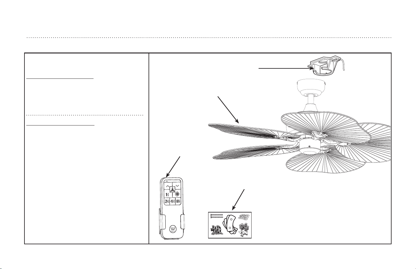
PARTS LIST
LISTA DE REPUESTOS
1
2
3
4
# . . . . . . . . . . . Description
1 . . . . . . . . . . . Mounting Bracket
2 . . . . . . . . . . . Blade
3 . . . . . . . . . . . Remote Control
4 . . . . . . . . . . . Hardware Pack
No. . . . . . . . . . . . Descripción
1 . . . . . . . . . . . Soporte de montaje
2 . . . . . . . . . . . Aleta
3 . . . . . . . . . . . Control Remoto
4 . . . . . . . . . . . Tornillería

ETL-ES-Oasis-Damp-WH25
and Westinghouse are trademarks of
We
stinghouse Electric Corporation.
Used under license
by Westinghouse Lighting.
All Rights Reserved.
Made in China
Westinghouse Lighting, Philadelphia, PA 19154-1029, U.S.A.
www.westinghouselighting.com