
MILWAUKEE TOOL
l
www.milwaukeetool.com
13135 W. LISBON RD., BROOKFIELD, WI 53005
Drwg. 2
Only maintenance, service, repairs, and replacements of parts as dened in the Operator's Manual
can be performed by the user.
All other repairs are to ONLY be performed by personnel authorized by MILWAUKEE TOOL. Do not
attempt to install other parts; this COULD void your tool warranty.
For service, parts, or inquiries, contact us:
• Customer Service at 1.800.SAWDUST (1.800.729.3878)
• E-Service tool repair at: www.milwaukeetool.com/e-service
• Find a local authorized MILWAUKEE service location at Milwaukeetool.com
• Find a MILWAUKEE factory Service Center Location or MILWAUKEE factory Central Repair
Center at Milwaukeetool.com. Send the following, posted paid and insured:
• Your name, address, and phone number
• Description of the issues
• Copy of the proof of purchase
• Tool, charger, and batteries involved with the issues
MILWAUKEE factory Central Repair Centers:
MILWAUKEE TOOL MILWAUKEE TOOL
Central Repair Central Repair
1401 Sycamore Avenue 2198 Southtech Drive
Greenwood, MS 38930 Greenwood, IN 46143
BULLETIN NO.
54-24-5021
SERVICE PARTS LIST
CATALOG NO. 2806-20
REVISED BULLETIN
SPECIFY CATALOG NO. AND SERIAL NO. WHEN ORDERING PARTS
M18™ FUEL™ One-Key™ Hammer-Drill
STARTING
SERIAL NO.
DATE
Feb. 2024
WIRING INSTRUCTION
J79B
SEE PAGE 3
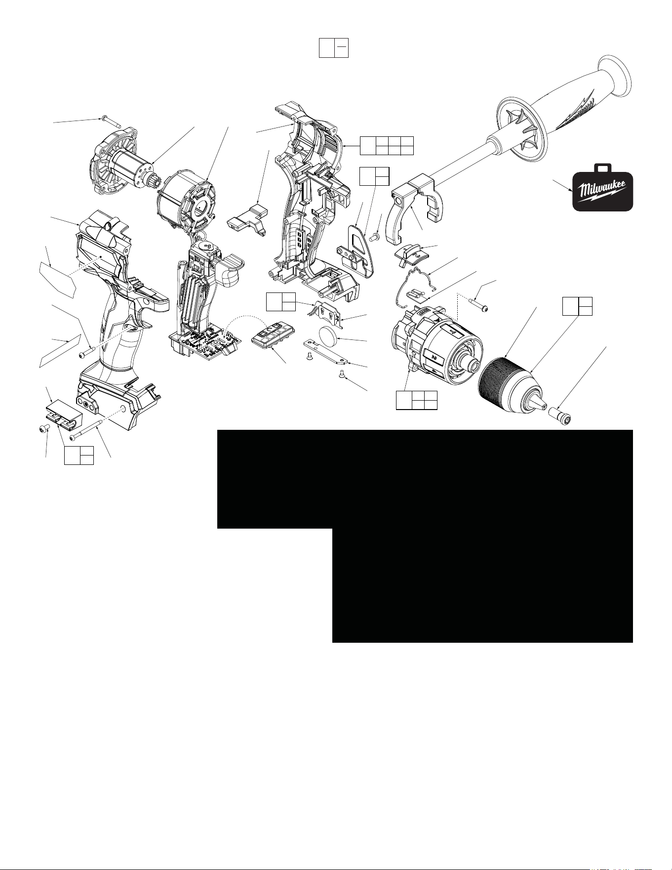
FIG. PART NO. DESCRIPTION OF PART NO. REQ.
1 05-88-0034 M8.0 x 1 LH T-40 Chuck Screw (1)
13 06-82-7337 M3 x 20mm Pan Hd. T-10 Screw w/Washer (4)
15 45-24-1045 Shift Spring (1)
16 42-42-3001 Forward/Reverse Shuttle (1)
20 --------------- Left Housing Halve - Support (1)
21 --------------- Coin Cell Board Assembly (1)
22 --------------- 3V Coin Cell Battery (CR 2032) (1)
23 31-15-0011 Coin Cell Cover (1)
24 05-81-1100 M2.6 x 6mm ST Phillips Screw (2)
25 --------------- Belt Clip (1)
26 06-82-2500 6-32 x 7mm Pan Hd. Slt. T-15 Mach. Screw (2)
34 06-82-7336 M3 x 20mm Pan Hd. ST T-10 Screw (4)
39 44-10-4002 Speed Selector Slide (1)
40 40-50-9001 Detent Spring (1)
41 --------------- Right Housing Halve - Cover (1)
43 --------------- Bit Holder Housing (1)
44 06-82-6350 M3 x 16mm Pan Hd. ST T-10 Screw (5)
EXAMPLE:
Component Parts (Small #) Are Included
When Ordering The Assembly (Large #).
0
00
40
39
15
13
(2x)
57
1
56
26
25
20
16
55
54
34
(4x)
21
22
23
24
(2x)
41
48
44
(5x)
49
43
26
45(2x)
46
58
25
26
52
26
43
50
15 39
40
53
20 41 44
45 48 49
51
REMOVING THE CHUCK SCREW:
Set the Speed Selector Slide (39) to the #1 setting.
With the aid of a small pencil tip torch (or use an air reduction nozzle on a heat gun) apply heat
into the chuck opening, directly to the head of reversing screw just prior to removing the screw.
Place a T40 1/4” torx bit into the head of the reversing screw and place a 1/4” boxed end wrench
over the hex on the T40 bit. It is recommended to use a 12”-18” metal tube or pipe as leverage
over the boxed wrench. In a clockwise direction apply a slow, steady force on the ‘cheater bar’
to break the screw loose.
REMOVING THE KEYLESS CHUCK:
Tighten a 3/8” or 10mm Allen Key into the jaws of the chuck. Place
the tool into a vise with soft jaws (this will require that you remove
the belt clip from the tool). It is recommended to use a 12”-18” metal
tube or pipe as leverage over the allen key. In a counter-clockwise
direction apply a slow, steady force on the ‘cheater bar’ to break the
chuck loose.
INSTALLING NEW CHUCK AND SCREW:
Torque Chuck to 1095 kgf-cm (950.418 lb-in or 79.20 lb-ft)
Torque Screw to 400 kgf-cm (347 lb-in or 28.93 lb-ft)
21
22
59
1
57
60
FIG. PART NO. DESCRIPTION OF PART NO. REQ.
45 06-82-2367 M3 x 38mmPan Hd. ST T-10 Screw (2)
46 42-55-9005 Blow Molded Carrying Case (1)
48 12-20-0478 Service Namelate (1)
49 10-20-1048 Warning Label (1)
50 43-72-0950 Bit Holder Kit (1)
51 31-44-2806 Housing Kit (1)
52 42-70-0950 Belt Clip Kit (1)
53 14-29-1014 Gearcase Assembly (1)
54 16-07-1016 Rotor Assembly (1)
55 14-20-2806 Electronic Assembly (1)
56 42-62-1002 Side Handle Assembly (1)
57 --------------- 1/2” Keyless Chuck (1)
58 45-24-2806 Wireless Selector Kit (1)
59 14-20-0068 Coin Cell Board Assembly with Battery (1)
60 42-66-0030 1/2” Keyless Chuck with Chuck Screw (1)
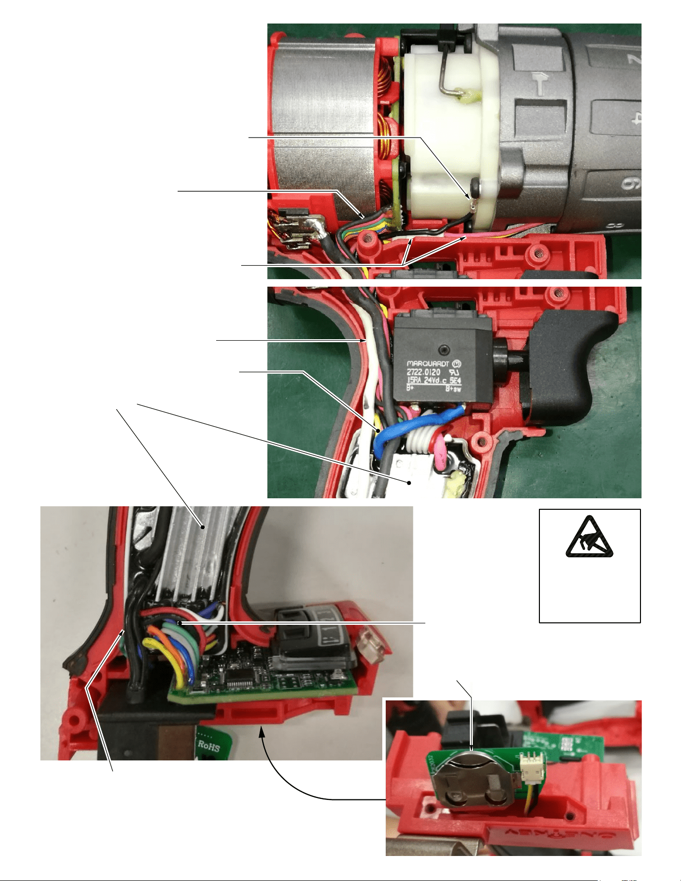
High voltage ground wire and terminal
Route these six wires close to stator
than down in housing halve cavity
behind on-off switch
Connect wires from gearcase assembly
with corresponding wires of potted circuit
board. Tuck wires and connectors in re-
cess under gearcase assembly than
down in housing halve cavity behind
on-off switch
All wires in this area are to be pushed
completly down into handle cavity behind
switch. Prevent pinched wires here when
putting housing cover in place
Keep blue wire away from heat sink
Heat Sink
Watch for pinched wires here
Keep wires away
from heat sink
3V coin cell battery
(CR 2032)
Be sure that all mechanical and electrical compo-
nents are placed rmly and squarely in the corre-
sponding cavities of left housing halve.
Be very careful and make sure that all wires and
the wire ribbon are placed rmly down in wire
channels and traps.
Make sure there are no interferences when install-
ing the right housing halve.
ATTENTION
OBSERVE PRECAUTIONS
FOR HANDLING
ELECTROSTATIC
SENSITIVE
DEVICES